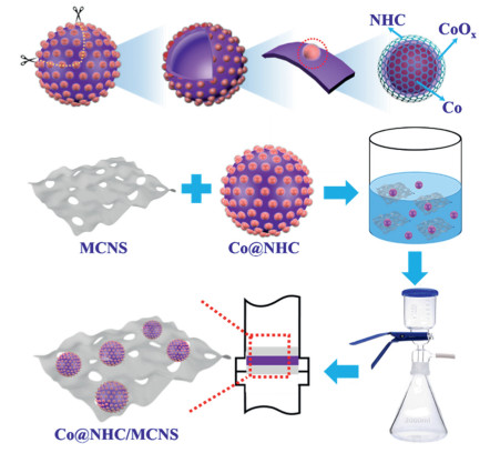
Scheme 1.
Schematic illustration for the synthesis process of Co@NHC/MCNS.
A candy-like photocatalyst by wrapping Co, N-co-doped hollow carbon sphere with ultrathin mesoporous carbon nitride for boosted photocatalytic hydrogen evolution
Jinyuan Liu , Shumin Zhu , Bin Wang , Ruizhe Yang , Rong Wang , Xingwang Zhu , Yanhua Song , Junjie Yuan , Hui Xu , Huaming Li

Semiconductor photocatalytic technology can convert solar energy into clean and renewable resources such as hydrogen energy. As the most potential energy carrier to replace fossil fuels, hydrogen has high combustion value and no additional carbon emissions [1, 2]. However, the catalytic efficiency of semiconductor photocatalysts for photocatalytic water splitting to produce hydrogen is still very low [3, 4]. Pt is often used as the cocatalyst [5], which shows the highest performance on the active volcano plot for hydrogen production from water splitting [6, 7]. Nevertheless, the high price and scarce Pt resources are not conducive to the large-scale production and application of Pt-based photocatalytic hydrogen production catalysts [8-10]. Therefore, the construction of low-cost, high-efficiency and stable photocatalyst is an important prerequisite for the development of hydrogen energy [11].
Mesoporous carbon nitride sheet (MCNS) has attracted extensive attention in the field of photocatalytic hydrogen production due to its large specific surface area, tunable energy band structure, and high light absorption capacity [12-14]. However, monomer production efficiency is limited by the low photo-generated carrier migration-separation efficiency and the high energy barrier at the active sites. At this time, the introduction of cocatalyst plays an important role in improving the photocatalytic hydrogen evolution performance of the catalysts. Among the cocatalysts, photocatalytic hydrogen evolution rate is effectively enhanced by designs of the morphologies and structures in the cocatalysts such as Ni-P clusters, Bi2Te3 nanorods [15-19]. But the stabilities of metals like nickel and bismuth act as cocatalysts is not enough in the photocatalytic process.
Carbon materials exhibit good electronic conductivity and outstanding stability. Therefore, the photocatalytic performance of carbon nitride modified by carbon materials such as CNTs, CQDs and lamellar graphene is effectively improved [20-24]. Additionally, studies have shown that the carbon sphere is expected to improve the migration and separation efficiency of photogenerated electrons in the photocatalysts [25-27]. However, compared with some metal catalysts, the photocatalytic activity of these non-metal catalysts still needs to be improved. The transition metals such as Fe and Pt can act as catalytically active centers to improve electrical conductivity and photocatalytic activity [28, 29]. In addition, nitrogen doping and transition metal loading can further enhance the electrical conductivity of the material and increase the active sites, thereby enhancing the catalytic performance [30, 31]. The composite of hollow carbon sphere loaded with transition metal nanoparticles and the MCNS are expected to further improve the photocatalytic hydrogen production performance.
Herein, cobalt nanoparticles supported nitrogen-doped hollow carbon spheres composite mesoporous carbon nitride sheet (Co@NHC/MCNS) have been successfully constructed by electrostatic adsorption (Scheme 1). Compared with NHC/MCNS and MCNS, the introduction of cobalt nanoparticles greatly enhances the hydrogen production of the NHC/MCNS under visible light irradiation. Under 4 h of λ ≥ 420 nm visible light irradiation, the hydrogen production rate of Co@NHC/MCNS material is 3675 µmol/g, which is 59 and 159 times higher than that of NHC/MCNS and MCNS, respectively. In this work, the carbon spheres can help the cobalt nanoparticles to disperse uniformly and stably. The advantage of carbon spheres can be attributed to: (a) Hollow carbon spheres are bridges between carbon nitride and cobalt nanoparticles, which play a role in accelerating charge transfer and inhibiting the recombination of photogenerated carriers; (b) The supporting role of hollow carbon spheres avoids the stacking of ultrathin MCNS to improve the photocatalytic activity. Besides, cobalt nanoparticles also play a crucial part in enhancing photocatalytic performance. The uniform loading of cobalt nanoparticles on the surface of hollow carbon spheres can effectively improve the photo-generated electron migration-separation performance of the composite. At the same time, it can increase more active sites for hydrogen evolution, thereby significantly improving the performance of photocatalytic water splitting.
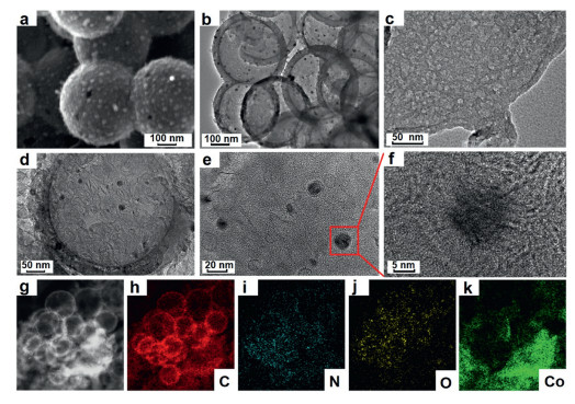
The morphologies of the SiO2@RF (resorcinol formaldehyde) spheres used to prepare hollow carbon spheres are clearly presented by TEM and SEM in Figs. S1a and c (Supporting information) [32, 33]. The images of TEM and SEM (Figs. S1b and d in Supporting information) prove the successful preparation of the hollow carbon spheres. Morphology of Co@NHC material can be seen from SEM and TEM. From the SEM image (Fig. 1a) of Co@NHC material, it can be shown that Co@NHC material has a typical sphere morphology and cobalt nanoparticles are also uniformly distributed on the surface of carbon sphere [34, 35]. Furthermore, the load of cobalt nanoparticles is the reason for which uneven surface can be observed. TEM analysis is employed to further explore the microstructure of Co@NHC material in Fig. 1b. The image shows hollow sphere-like structure, existing black dots further revealing that cobalt nanoparticles are loaded successfully. Pure mpg-C3N4 material displays ultrathin 2D nanosheet structure (Fig. 1c) [36]. Meanwhile, the obvious micropores of the surface prove that the material is mesoporous carbon nitride. In addition, the average thickness of pure mpg-C3N4 material is about 1.13 nm from Supporting information AFM (Fig. S2 in Supporting information). The wrap of ultrathin mpg-C3N4 leads to the appearance of corrugation. It can be seen that Co@NHC material is uniformly wrapped by the ultrathin mpg-C3N4 (Fig. 1d and Fig. S3 in Supporting information). Moreover, high resolution TEM images have shown cobalt nanoparticles are dispersed on hollow carbon sphere, and there are apparent lattice fringes of carbon nitride to be observed in Figs. 1e and f. The energy-dispersive X-ray spectroscopy (EDS) elemental mapping images (Figs. 1g-k) show the even distribution of carbon, nitrogen, oxygen and cobalt [36].
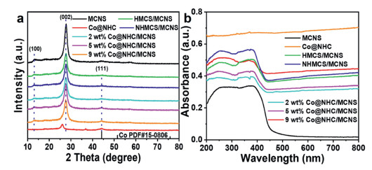
The crystal structures of the samples are characterized by XRD analysis in Fig. 2a [37]. The distinct diffraction peaks of MCNS material at 13° and 27.6° are assigned to the (100) and the (002) crystal planes, which can be attributed to the intralayer structural packing and the interlayer stacking of graphitic carbon nitride [38, 39]. For Co@NHC material, the diffraction peaks are located at 26° and 44.3° [40], representing the (002) crystal plane of carbon peak and the (111) crystal plane of metallic cobalt. Compared with MCNS material, it is obvious that the (002) peaks of other samples are weakened because the decrease of MCNS content. Meanwhile, it can be seen that no obvious peaks of metallic cobalt in the Co@NHC/MCNS materials, which may be ascribed to the low content of Co@NHC material in the complex. In addition, there is no other characteristic peaks of impurities are detected, manifesting the high purity of these materials. The light absorption capacity of the MCNS, Co@NHC and Co@NHC/MCNS materials are investigated by DRS (Fig. 2b). The Co@NHC material shows total absorption in DRS because of its black characterization [41]. With increasing the laden Co@NHC content in hybrid, the absorption intensity in the range of visible light gradually increases and the absorbing edges of the MCNS material still remain. Brunnauer-Emmett-Teller (BET) analysis of samples including MCNS, Co@NHC and 5 wt% Co@NHC/MCNS are investigated to measure the specific surface area of these samples (Fig. S4 in Supporting information). The IV isotherm with evident H1 hysteresis lines can be obviously observed, indicating the existence of mesoporous structure in three kinds of materials [42]. Surface area of MCNS (150.973 m2/g) is close to the surface area of Co@NHC (148.016 m2/g). Both of surface areas are generally 3.1 times that of 5 wt% Co@NHC/MCNS (48.445 m2/g). The obvious decrease in the specific surface area of the composites indicates that the area is not the key role of the photocatalytic activity.
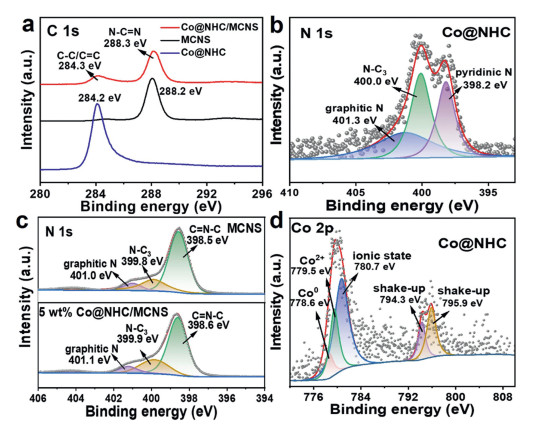
Moreover, the XPS spectra is adopted to research the chemical states of the prepared samples in Fig. 3. The spectrum of Co@NHC manifests the existence of elements such as C, O and N (Fig. S5 in Supporting information). In addition, it is clearly observed that C, N and O elements also appear in MCNS material and 5 wt% Co@NHC/MCNS material. The high-resolution C 1s spectrum of Co@NHC (Fig. 3a) owns one peak at 284.2 eV corresponding to carbon species (C—C/C═C) and MCNS has an obvious peak at 288.2 eV attributed to sp2-hybridized carbon (N—C═N) [43]. Compared with Co@NHC and MCNS, Co@NHC/MCNS possesses two apparent peaks at 284.3 and 288.3 eV respectively. It can be found that the peak of complex is shifted due to the interaction between Co@NHC material and MCNS material. The high-resolution N 1s spectrums of samples are acquired to investigate nitrogen species under deconvolution (Figs. 3b and c). There are three peaks existing in Co@NHC at 398.2 eV (pyridinic N), 400.0 eV (N—C3) and 401.3 eV (graphitic N). And the N 1s spectra of MCNS also shows the existence of some nitrogen bonds such as C═N—C (398.5 eV), N—C3 groups (399.8 eV) and graphitic N (401.0 eV). The Fig. 3c exhibits three similar peaks at 398.6 eV, 399.9 eV and 401.1 eV which are ascribed to the combination of chemical bonds like C═N—C, N—C3 and graphitic N respectively [44]. The peaks reveal 0.1 eV shift to higher binding energy compared with the peaks of the MCNS, attributing to the strong interaction in the 5 wt% Co@NHC/MCNS material. The peak intensity of cobalt in the XPS analysis is weak on account of the low cobalt content in the 5 wt% Co@NHC/MCNS. Nonetheless, the Co 2p XPS spectrum of Co@NHC is performed (Fig. 3d), there is an obvious main peak fitted by three peaks where are respectively at 778.6, 779.5 and 780.7 eV. The characteristic peak (778.6 eV) intensity of zero-valent cobalt is relatively weak because of the small cobalt content in the Co@NHC. The clear peak (779.5 eV) is corresponding to Co2+ for Co—O due to the close contact of cobalt and oxygen on carbon nitride [45]. Another characteristic peak (780.7 eV) is the ionic state of Co. There are shake-up peaks (794.3 and 795.9 eV) in Fig. 3d. The results of the XPS analysis are accordance with the XRD analysis [46].
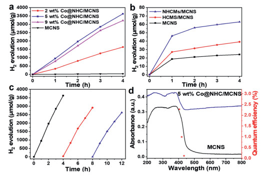
The photocatalytic hydrogen evolution performance tests of catalytic samples are performed under visible light irradiation. Fig. 4a shows that the hydrogen evolution of MCNS material without cocatalyst is very low, reaching the yield of 23 µmol/g for 4 h. The hydrogen evolution of 9 wt% Co@NHC/MCNS and 2 wt% Co@NHC/MCNS are 3210 µmol/g and 1595 µmol/g under visible light irradiation for 4 h, respectively. After introducing the Co@NHC material, hydrogen evolution is significantly improved. Especially, the hydrogen evolution of 3675 µmol/g is achieved by 5 wt% Co@NHC/MCNS, which is approximately 159 times than that of MCNS. Although the hydrogen evolution efficiency of 5 wt% Co@NHC/MCNS is not as high as that of some catalysts containing nickel co-catalysts, its photocatalytic performance is better than that of general catalysts compared with some catalytic performance reported (Table S1 in Supporting information). The excessive cobalt content in the 9 wt% Co@NHC/MCNS leads to a decrease of hydrogen evolution. It may be that the excessive black Co@NHC is not conducive to the light absorption of MCNS material. A set of control variables are displayed in Fig. 4b. Compared with MCNS material, the hydrogen evolution of HMCS/MCNS with 38 µmol/g shows a small improvement under 4 h of visible light exposure. And, the hydrogen production for NHMCS/MCNS is found to be 62 µmol/g, which is 2.7 times of MCNS, indicating that the doping of nitrogen is beneficial to enhance the photocatalytic activity. Cyclic test reveals the favorable stability and activity of 5 wt% Co@NHC/MCNS for hydrogen evolution (Fig. 4c). In addition, the structure stability of the 5 wt% Co@NHC/MCNS after three photocatalytic H2 generation cycles was verified by XRD in Fig. S6 (Supporting information). It can be seen that the (100) and (002) crystal planes belonging to the carbon peak are detected, and the (111) crystal plane representing metallic cobalt still exists. This indicated the 5 wt% Co@NHC/MCNS possess good structure stability. Wavelength dependence of apparent quantum efficiency (AQE) (Fig. 4d) is measured to investigate the function of Co@NHC on hydrogen evolution activity for MCNS. The result reveals that introducing 5 wt% Co@NHC conserves the band-gap of MCNS. The AQE of 5 wt% Co@NHC/MCNS is performed to better see the photocatalytic property in Fig. 4d. The AQE of 2.4, 1.0 and 0.1% for 5 wt% Co@NHC/MCNS are obtained with irradiations at 410, 420 and 435 nm, respectively. The carbon material is used as a co-catalyst, which has excellent charge transport properties to improve the charge separation rate. Therefore, the quantum efficiency and the photocatalytic performance 5 wt% Co@NHC/MCNS can be enhanced.
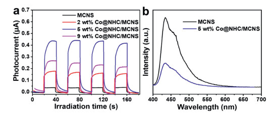
As shown in Fig. 5a, the photocurrent intensity of Co@NHC/MCNS in various proportions is apparently stronger than that of MCNS with 0.03 µA. Especially, the photocurrent of 5 wt% Co@NHC/MCNS with 0.44 µA is almost 15 times as high as MCNS, which keeps nearly unchanged. It can be indicated that the proper introduction of Co@NHC helps the MCNS acquire better ability for separation and transfer of photogenerated electron and hole pairs. PL spectrum (Fig. 5b) shows that 5% weight of Co@NHC in the composite reduces the intensity of photoluminescence in comparison with MCNS. The recombination of photo-generated holes and electrons has been effectively decreased. The result is in accordance with previously published work [47, 48].
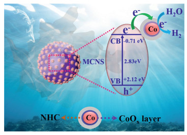
Based on the previous experimental data, this work proposes the photocatalytic hydrogen evolution mechanism of Co@NHC/MCNS in Scheme 2. Firstly, MCNS photocatalyst can be motivated to produce photogenerated holes and electrons when exposed to light. Next, the photogenerated electrons distributed in the MCNS fleetly transfer to the conduction bands and then shift to the carbon layer. After that, these electrons existing in the carbon layer move on to the cobalt nanoparticles wrapped by carbon layer. Ultimately, the transferred electrons react with H+ on the cobalt nanoparticles to produce H2 under light irradiation.
In conclusion, cobalt nanoparticles are successfully assembled onto nitrogen-doped hollow carbon spheres through covalent bonding and tightly wrapped by ultrathin carbon nitride. The work reveals that 5 wt% Co@NHC/MCNS material with 3675 µmol/g is 159 times than pure MCNS material in the photocatalytic activity of hydrogen evolution with 4 h reaction time. The carbon layer in the Co@NHC/MCNS can effectively accelerate the transfer of charge, thereby greatly enhancing the rate of water splitting to produce hydrogen under visible light irradiation. It is also confirmed that the introduction of cobalt nanoparticles is an important factor to enhance the photocatalytic performance of MCNS. In addition to enhancing light absorption and reducing electron-hole recombination, the redox activity of the composite is also found to be greatly improved. Ultimately, the photocatalytic hydrogen evolution activity is effectively advanced.
The authors declare that they have no known competing financial interests or personal relationships that could have appeared to influence the work reported in this paper.
This study is financially supported by the National Natural Science Foundation of China (Nos. 22008095, 22108106, 22075113, 22108110), the Special China Postdoctoral Science Foundation (Nos. 2020TQ0127, 2020M680065), Jiangsu Province Postdoctoral Science Foundation (No. 2021K396C), Key Laboratory of Electrochemical Energy Storage and Energy Conversion of Hainan Province (No. KFKT2021006), Jiangsu Funds for Distinguished Young Scientists (No. BK20190045), Natural Science Foundation of Jiangsu Province (No. BK20190981), Basic and Applied Basic Research Fund Project of Guangdong Province (No. 2019A1515111020).
Supplementary material associated with this article can be found, in the online version, at doi:
L. Wei, Y.J. Chen, Y.P. Lin, et al., Appl. Catal. B: Environ. 144 (2014) 521-527. doi: 10.1016/j.apcatb.2013.07.064
S. Zhao, Y.W. Zhang, J.S. Fang, et al., ACS Sustain. Chem. Eng. 6 (2018) 8291-8299. doi: 10.1021/acssuschemeng.8b00300
Z.M. Pan, G.G. Zhang, X.C. Wang, Angew. Chem. Int. Ed. 58 (2019) 7102-7106. doi: 10.1002/anie.201902634
T. Hisatomi, K. Domen, Nat. Catal. 2 (2019) 387-399. doi: 10.1038/s41929-019-0242-6
H.Q. Fan, X.K. Zheng, Q. Shen, et al., J. Alloy Compd. 909 (2022) 164693. doi: 10.1016/j.jallcom.2022.164693
T.D. Nguyen-Phan, A.E. Baber, J.A. Rodriguez, et al., Appl. Catal. A: Gen. 518 (2016) 18-47. doi: 10.1016/j.apcata.2015.12.012
C.C. Han, Y. Lu, J.L. Zhang, et al., J. Mater. Chem. A 3 (2015) 23274-23282. doi: 10.1039/C5TA05370F
Y.J. Si, Y.J. Zhang, L.H. Lu, et al., Appl. Catal. B: Environ. 225 (2018) 512-518. doi: 10.1016/j.apcatb.2017.12.010
J.Z. Liu, Y.H. Li, X.D. Zhou, et al., J. Mater. Chem. A 8 (2020) 17-26. doi: 10.1039/c9ta10568a
M. Aksoy, O. Metin, ACS Appl. Nano Mater. 3 (2020) 6836-6846. doi: 10.1021/acsanm.0c01208
R.F. Chen, Y. Wang, Y. Ma, et al., Nat. Commun. 12 (2021) 1354. doi: 10.1038/s41467-021-21527-3
N. Zhao, Y. Feng, H.J. Zhao, et al., J. Alloy Compd. 901 (2022) 163566. doi: 10.1016/j.jallcom.2021.163566
Y.Y. Jiang, J. Xie, Z.J. Lu, et al., J. Colloid Interf. Sci. 612 (2022) 111-120. doi: 10.1051/metal/2021101
X. Zhang, C.J. Xi, Y.H. Yue, et al., Int. J. Hydrogen Energy 47 (2022) 1624-1632. doi: 10.1016/j.ijhydene.2021.10.225
Y.J. Wang, Y. Li, S.W. Cao, et al., Chin. J. Catal. 40 (2019) 867-874. doi: 10.1016/S1872-2067(19)63343-7
L. Dong, X.F. Wang, P. Wang, et al., J. Mater. Chem. 10 (2022) 6402-6410. doi: 10.1039/d2tc00594h
H. Zhao, J.W. Wang, Y.M. Dong, et al., ACS Sustain. Chem. Eng. 5 (2017) 8053-8060. doi: 10.1021/acssuschemeng.7b01665
J. Dong, Y. Shi, C.P. Huang, et al., Appl. Catal. B: Environ. 243 (2019) 27-35. doi: 10.1016/j.apcatb.2018.10.016
L. Li, J.J. Yi, X.W. Zhu, et al., ACS Sustain. Chem. Eng. 8 (2020) 884-892. doi: 10.1021/acssuschemeng.9b05248
M. Baca, M. Dworczak, M. Aleksandrzak, et al., Int. J. Hydrogen Energy 45 (2020) 8618-8628. doi: 10.1016/j.ijhydene.2020.01.105
M. Victor, T. Jing, W. Jie, et al., Environ. Chem. Lett. 18 (2020) 1413-1422. doi: 10.1007/s10311-020-01008-7
T.Y. Liu, F. Zhang, Y. Song, et al., J. Mater. Chem. A 5 (2017) 17705-17733. doi: 10.1039/C7TA05646J
S. Zhao, T. Guo, X. Li, et al., Appl. Catal. B: Environ. 224 (2018) 725-732. doi: 10.1016/j.apcatb.2017.11.005
Y.Y. Wu, C.F. Fu, Q. Huang, et al., ACS Nano 15 (2021) 7586-7595. doi: 10.1021/acsnano.1c01105
S.J. Phang, L.L. Tan, Catal. Sci. Technol. 9 (2019) 5882-5905. doi: 10.1039/c9cy01452g
L.T. Ma, H.Q. Fan, K. Fu, et al., ACS Sustain. Chem. Eng. 5 (2017) 7093-7103. doi: 10.1021/acssuschemeng.7b01312
G.H. Wang, J. Hilgert, F.H. Richter, et al., Nat. Mater. 13 (2014) 294-301.
X.J. Fan, Z.W. Peng, R.Q. Ye, et al., ACS Nano 9 (2015) 7407-7418. doi: 10.1021/acsnano.5b02420
H.L. Tian, H.Q. Fan, J.W. Ma, et al., J. Hazard. Mater. 341 (2018) 102-111. doi: 10.1016/j.jhazmat.2017.07.056
Y.Q. Zhang, X.H. Xia, X. Cao, et al., Adv. Energy Mater. 7 (2017) 1700220. doi: 10.1002/aenm.201700220
J. W. Fang, H.Q. Fan, M.M. Li, et al., J. Mater. Chem. A 3 (2015) 13819-13826. doi: 10.1039/C5TA02257F
W. Li, F.F. Yang, Z.H. Hu, et al., J. Alloy Compd. 749 (2018) 305-312. doi: 10.1016/j.jallcom.2018.03.046
J.Y. Liu, H. Xu, H.P. Li, et al., Appl. Catal. B: Environ. 243 (2019) 151-160. doi: 10.1021/acs.accounts.8b00429
B. Wang, J. Di, L. Lu, et al., Appl. Catal. B: Environ. 254 (2019) 551-559. doi: 10.1016/j.apcatb.2019.04.068
Y.Z. Guo, J.H. Yang, D.H. Wu, et al., J. Mater. Chem. A 8 (2020) 16218-16231. doi: 10.1039/d0ta03793a
Q.X. Liu, C.M. Zeng, Z.H. Xie, et al., Appl. Catal. B: Environ. 254 (2019) 443-451. doi: 10.1016/j.apcatb.2019.04.098
B. Wang, S.Z. Yang, H.L. Chen, et al., Appl. Catal. B: Environ. 277 (2020) 119170. doi: 10.1016/j.apcatb.2020.119170
W.G. Liu, W.J. Hu, L.J. Yang, et al., Nano Energy 73 (2020) 104750. doi: 10.1016/j.nanoen.2020.104750
P. Zhang, D.R. Sun, A. Cho, et al., Nat. Commun. 10 (2019) 940. doi: 10.1038/s41467-019-08731-y
J.Y. Liu, L. Xu, Y.L. Deng, et al., J. Mater. Chem. A 7 (2019) 14291-14301. doi: 10.1039/c9ta01234f
B. Wang, J.Z. Zhao, H.L. Chen, et al., Appl. Catal. B: Environ. 293 (2021) 120182. doi: 10.1016/j.apcatb.2021.120182
R. Z. Yang, J. Y. Liu, B. Wang, et al., J. Alloy Compd. 895 (2022) 162290. doi: 10.1016/j.jallcom.2021.162290
P. Niu, M. Qiao, F.Y. Li, et al., Nano Energy 44 (2018) 73-81. doi: 10.1016/j.nanoen.2017.11.059
D.M. Zhao, Y.Q. Wang, C.L. Dong, et al., Nat. Energy 6 (2021) 388-397. doi: 10.1038/s41560-021-00795-9
Y.J. Cao, S. Chen, Q.Q. Luo, et al., Angew. Chem. Int. Ed. 56 (2017) 12191-12196. doi: 10.1002/anie.201706467
B. Wang, Y.Z. Ye, L. Xu, et al., Adv. Funct. Mater. 30 (2020) 2005834. doi: 10.1002/adfm.202005834
J.W. Fu, C.B. Bie, B. Cheng, et al., ACS Sustain. Chem. Eng. 6 (2018) 2767-2779. doi: 10.1021/acssuschemeng.7b04461
B. Wang, W. Zhang, G. Liu, et al., Adv. Funct. Mater. (2022) 202202885.

Figure 1 (a) SEM image of the Co@NHC. TEM images of the (b) Co@NHC, (c) MCN, and (d) Co@NHC/MCNS. (e, f) High resolution TEM images of Co nanoparticles in the Co@NHC/MCNS. (g-k) EDS elemental mapping image of Co@NHC/MCNS.

Figure 3 High-resolution spectra of (a) C 1s, (b, c) N 1s and (d) Co 2p of MCNS, Co@NHC and 5 wt% Co@NHC/MCNS.

Figure 4 (a, b) Photocatalytic hydrogen efficiency of samples. (c) Stability test of hydrogen evolution of 5 wt% Co@NHC/MCNS. (d) Wavelength dependence of AQE for 5 wt% Co@NHC/MCNS.

Figure 5 (a) Transient photocurrents of MCNS and Co@NHC/MCNS. (b) Photoluminescence spectrums of samples.

 扫一扫看文章

扫一扫关注我们
 DownLoad:

 下载:
下载:

