Received Date:
08 May 2022 Accepted Date:
21 June 2022 Revised Date:
28 May 2022 Available Online:
15 February 2023
Abstract:
Aqueous zinc-ion batteries (AZIBs) have aroused significant research interest around the world in the past decade. The use of low-cost aqueous electrolytes and a metallic Zn anode with a suitable redox potential and high energy density make AZIBs a potential alternative to commercial Li-ion batteries in the development of next-generation batteries. However, owing to the narrow electrochemical stability window (ESW) of aqueous electrolytes, the choice of cathode materials is limited, because of which AZIBs exhibit a relatively low operating voltage and energy density. Hence, expanding the ESW of aqueous electrolytes is important for the development of practical AZIBs. This paper systematically reviews the electrolyte engineering strategies being explored to broaden the ESW of AZIBs. An in-depth analysis of high-voltage AZIBs is also presented. We suggest that the realization of high-voltage AZIBs depends on the synergistic development of suitable electrolytes and cathode materials. In addition, the cost associated with their fabrication as well as the use of standardized electrochemical tests should be considered during the design of high-voltage AZIBs.
Li-ion batteries (LIBs) have gradually become the most common secondary batteries in the market since their commercialization in the early 1990s [1-6]. Although the outstanding energy density and cyclability of LIBs distinguish them from conventional secondary batteries (e.g., lead-acid batteries) [7], the safety issues arising to their use of flammable organic electrolytes and the dwindling sources for their raw materials (e.g., Li, Co and Ni minerals) suggest that LIBs may not be able to meet the ever-growing energy requirements related to regional and global carbon neutrality [8]. Therefore, novel battery systems that exhibit high energy density and are safe, cheap, and environmentally friendly must be developed as potential alternatives to commercial LIBs [9, 10].
Aqueous zinc-ion batteries (AZIBs) meet the above-stated requirements [11-13]. Owing to their unique advantages, including their use of nonflammable and low-cost aqueous electrolytes, a metallic Zn anode with a relatively high energy density and suitable redox potential, and undemanding fabrication conditions (open air), AZIBs have attracted significant research interest in the past few years. Hence, considerable resources are being devoted to their development [14-16], and the number of studies on AZIBs has increased exponentially in the past five years (Fig. 1a) [17-19]. Considering that AZIBs have not yet been commercialized, an acceptable first estimation of the specific energy of AZIBs can be described as follows [20]:
(1)
Figure 1
Figure 1.
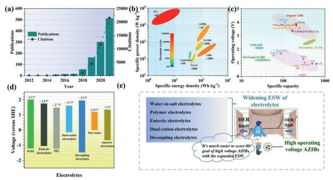
(a) Number of scientific peer-reviewed publications and citations on AZIBs. Data were collected in May 2022 from clarivate web of science. (b) Comparison of energy density and power density of different secondary batteries [6, 23-25]. (c) Comparison of operating voltage and specific capacity of different secondary batteries. (d) The electrochemical stability window of the aqueous electrolytes of AZIBs [26-28]. (e) Schematic illustration of scoring the goal of fabricating high voltage AZIBs through the electrolytes engineering and developing high-voltage cathodes developing.
where the Qcat and Qan are the specific capacities of the active materials used in the cathode and anode, respectively. Further, ∆Vcell is the average discharge voltage of the cell. Compared with commercial LIBs and other conventional secondary batteries, state-of-the-art AZIBs show a remarkably higher specific power density (104–105 W/kg) and greater cyclability (> 10,000 cycles) [5, 21, 22]. The specific energy density of AZIBs (50–200 Wh/kg) is also comparable to that of commercial LIBs (70–250 Wh/kg, Fig. 1b) [23]. However, while these properties seem satisfactory, in most cases, the AZIBs in question were characterized using coin cells while the compared commercial LIBs were assembled in the form of pouch cells [6, 24, 25]. In addition, there remains a significant gap in the practical energy densities of AZIBs and LIBs, owing to the much lower operating voltage of AZIBs. The operating voltages of the commercial LIBs are normally higher than 3.0 V, while those of AZIBs are lower than 1.5 V, except for decoupling Zn-Mn batteries (greater than 2.0 V) [26-28]. On the other hand, the specific capacity (> 600 mAh/g for some vanadium cathodes) of AZIBs is much higher than that of LIBs and approaches the theoretical capacity of metallic zinc (820 mAh/g, Fig. 1c).
Increasing the nominal voltage and specific capacity is equally important for improving the energy density of the batteries. Considering that the anode material is metallic zinc, which has a significantly higher specific capacity than that of the cathode material and a fixed redox potential, the operating voltage and specific capacity of AZIBs are primarily dependent on the choice of the cathode material. However, the list of cathode materials suitable for AZIBs is relatively short because the electrochemical stability window (ESW) of aqueous electrolytes is narrowed by the hydrogen evolution reaction (HER) and oxygen evolution reaction (OER) [29-32]. The water decomposition potential is 1.23 V at approximately 25 ℃. Because AZIBs generally use electrolytes based on mildly acidic zinc salts (e.g., ZnSO4 and ZnCl2) and given the overpotential of the anodic HER and cathodic OER, the ESW of aqueous electrolytes can be as high as 2.0 V [33]. Hence, transition metal oxides (TMOs; primarily vanadate/manganese oxide) [34-39], Prussian blue analogues (PBAs) [40, 41], organics [42-46] and polyanionic compounds [47, 48] are the most widely used cathode materials for AZIBs owing to their moderate voltage range within the ESW of aqueous electrolytes. However, none of them exhibits an operating voltage comparable to that of LIBs. PBAs (~1.6 V) and polyanionic compounds (~1.7 V) exhibit relatively higher operating voltages than those of TMOs (< 1.5 V) and organics (~1.0 V) but have much lower specific capacities. Meanwhile, decoupling Zn batteries show both high operating voltages (2.3–2.7 V) and high specific capacities because of the acidic Mn2+/MnO2 and alkaline Zn redox reactions that occur in them [27, 49-51]. However, their applicability is hindered by their high cost (owing to the use of a selective membrane) and complex fabrication process [52-55].
Therefore, the low operating voltage of AZIBs is responsible for the previously mentioned energy density gap between LIBs and AZIBs. Hence, broadening the ESW of aqueous electrolytes is essential for increasing the operating voltage of AZIBs. The mainstream strategies being explored for expanding the ESW of the aqueous electrolytes used in AZIBs are summarized in Fig. 1d; the corresponding ESWs are also shown. "Water-in-salt" electrolytes (WiSEs), polymer electrolytes (PEs), eutectic electrolytes, dual-cation electrolytes, and decoupling electrolytes have been reviewed in this paper. By modifying the composition/content of the solvend and solvent and using decoupling electrolyte systems, the ESW of aqueous electrolytes can be made higher than those of water and common aqueous electrolytes. The relationship between the ESW of aqueous electrolytes and the operating voltage of AZIBs can be considered similar to a striker taking a shot in a football match. The widening of the electrolyte ESW through delaying the anodic HER and cathodic OER limits of the electrolyte is similar to expanding interspace of the goalposts in front of the striker trying to take a shot. With the expanded ESW, the cathode materials can be deeper discharged with higher specific capacity, and more novel cathode materials can be developed for the enlarged ESW, just like the striker can score more easily with the expanded goal in the football match (Fig. 1e) [56].
2.
Water splitting and solvation structure of Zn2+ in aqueous electrolytes
Water decomposition is affected by the pH of the electrolyte, and the reactions involved can be summarized as shown below:
OER at cathode side:
(2)
(3)
HER at anode side:
(4)
(5)
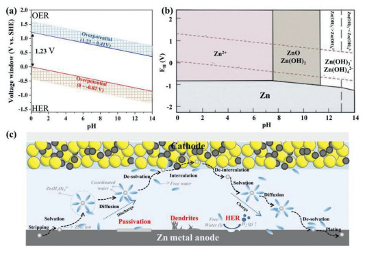
The relationship between the potentials of the HER/OER and the pH is shown in the Pourbaix diagram in Fig. 2a. The ESW of water, which is limited by the HER and OER, is 1.23 V. In addition, the activation of both the HER and OER requires significant polarization (i.e., a high overpotential) to overcome the intrinsic activation barriers at the cathode and anode as well as the solution and contact resistances. Hence, the actual ESW of water is greater than 1.23 V (indicated by the shadow parts in Fig. 2a) [29, 31, 57].
Figure 2
Figure 2.
(a) Pourbaix diagram of water. (b) Pourbaix diagram of the Zn/H2O diagram. Reproduced with permission [58]. Copyright 2010, Springer. (c) Schematic illustration of zinc ions transportation and issues of AZIBs caused by free water.
The reaction mechanism of the Zn anode is also pH dependent. For conventional alkaline Zn-based batteries (AZBs), which use alkaline electrolytes that undergo cathode conversion reactions (i.e., alkaline Zn-Mn and Zn-Ni batteries), the anodic reaction is as shown below:
(6)
The poor reversibility of the Zn/Zn(OH)42− redox pair and the low energy density of AZBs limit their use in large-grid energy storage systems. On the other hand, the typical electrolytes for AZIBs are mildly acidic solutions mixed with a Zn salt and water with pH values of approximately 4–5.5. According to the results shown in Fig. 2b, for AZIBs with mildly acidic electrolytes, the anode reaction can be summarized as shown below:
(7)
The reversible Zn/Zn2+ electrode outputs a standard electrode potential of −0.76 V, which makes Zn anodes thermodynamically unstable in aqueous electrolytes during the charging/discharging processes. Thus, the ESW of aqueous electrolytes is limited (see the Pourbaix diagram [58] in Fig. 2b). Compared to the case for AZBs, the HER occurs readily in mildly acidic electrolytes owing to the significantly higher potential of the Zn/Zn2+ pair. On the other hand, mildly acidic electrolytes also ensure a reversible intercalative mechanism for high-capacity cathodes. Finally, the use of these electrolytes also ensures that the Zn anode exhibits higher cyclability and greater environmental friendliness compared with that when an alkaline electrolyte system is used [59].
The presence of water during the Zn stripping/plating and diffusion processes triggers a series of side reactions in aqueous electrolytes. As illustrated in Fig. 2c, instead of existing alone in the aqueous environment, the Zn ions are normally coordinated by two layers of water molecules. The number of inner water molecules varies with the solvent environment (i.e., the pH, solvent, and solvend). In the case of the most used electrolyte, that is, ZnSO4, the Zn ions coordinate with six dipolar water molecules in the inner layer and form hydration coordination bonds [44, 60]. The outer layer consists of free water molecules loosely combined with the water molecules of the inner layer through hydrogen bonds. The Zn ions go through stripping/plating-solvation/desolvation-diffusion during the discharging/charging of the AZIB. During the stripping/plating process, the water molecules undergo solvation/desolvation with the Zn ions; this process can be summarized as shown below:
(8)
During the Zn plating process, charge transfer occurs via the Zn-OH2 bond of the cation-solvation structure, with the electrons departing the 3a1 bonding molecular orbital of the coordinated water for the empty Zn2+ orbitals. Significantly weakened O—H bonds are formed within the water molecules [61, 62]. In addition, both layers of the water molecules desolvate from the Zn(H2O)62+ ions, resulting in the discharge of a large number of free water molecules with weaker H—O bonds than those of the bulk water molecules. As a result, the free water molecules are more activated in electrochemical reactions such as the HER. The HER (Eq. 5) at the Zn anode often leads to the formation of H2 gas as well as a decrease in the Coulombic efficiency (CE) and an increase in the local pH value with the consumption of the H+ ions. The corrosion and passivation of the Zn anode follow as the pH increases, leading to a decrease in the cycling life and CE of the AZIB [63-65].
Therefore, the suppression of the free water and regulation of the solvation-sheath structure of the Zn ions are the keys to overcome the HER/OER-related limitations and broaden the ESW of aqueous electrolytes.
3.
Electrolyte engineering for broadening ESW of AZIBs
3.1
WiSEs
Electrolytes in which both the mass and volume of the salt exceeds those of the solvent are defined as WiSEs [66]. Therefore, only the salts with high solubility in water can be used as WiSEs. The ESW of aqueous electrolytes can be expanded beyond 3.2 V using WiSEs, because WiSEs directly decrease the water content of aqueous electrolytes. Almost all the remaining water molecules are coordinated with Zn ions, resulting in a decrease in the number of free water molecules. Meanwhile, the solvation sheath of the Zn ions is also regulated when fewer coordinated water molecules are presented. This promotes the kinetics of charge transfer as well as the solid-state diffusion processes of the Zn ions [67]. Owing to the high solubility in the water, ZnCl2 [40, 46, 68, 69], LiTFSI [70], NaClO4 [71], KOAc [72], Zn(OTf)2 [73] have been applied as the concentrated solvent in aqueous electrolyte.
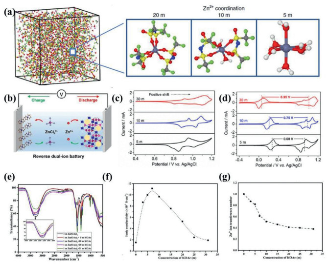
A study by Wang et al. can be considered a representative one on a highly concentrated Zn-ion electrolyte (HCZE, 1 m Zn(TFSI)2 + 20 m LiTFSI, (1 m = one mole of solute in one kg of solvent) [70]. They showed that the pH of the HCZE increased from 3 (1 m Zn(TFSI)2) to approximately 7 (1 m Zn(TFSI)2 + 20 m LiTFSI). This was because the interactions of the Zn2+ ions with the water molecules were suppressed, thus limiting the hydrolysis of water. In addition, they used Fourier transform infrared spectroscopy (FTIR) to prove that the hydrogen bonds of the water molecules were weakened, and the water network in the bulk electrolyte was disrupted. The results of nuclear magnetic resonance (NMR) spectroscopy further confirmed that the water molecules were confined by the high concentration of the Li salt and interacted to a smaller degree with the Zn2+ ions. This was the reason for the observed increase in the pH. The solvation structure of the Zn2+ ions was studied through molecular dynamics (MD) simulations. As shown in Fig. 3a, a single Zn2+ ion coordinated with six water molecules instead of a TFSI− ion. However, with the increase in the LiTFSI concentration, the anions started to enter the solvation sheath of the Zn2+ ions to form the cluster of Zn(TFSI)m(H2O)n. For the HCZE with the highest concentration of the Li salt (20 m), the solvation sheath was occupied by the oxygen atoms from TFSI−, which replaced the six-dipolar-coordinated water in the low-concentration HCZE. Density functional theory (DFT) calculations further proved that the HER was inevitable with the presence of water in the solvation sheath because the reduction potential of TFSI is lower than that of the HER. However, in the Zn(TFSI)62+ clusters, no water existed in the Zn2+ion solvation sheath, which prevented the HER and resulted in a high CE (≈100) for Zn plating/stripping.
Figure 3
Figure 3.
(a) Snapshot of the MD simulation cell for HCZE (1 m Zn(TFSI)2 + 20 m LiTFSI) and the zinc-ions-solvation structures in the 1 m Zn(TFSI)2 + 5, 10 and 20 m LiTFSI. Reproduced with permission [70]. Copyright 2018, Nature Springer. (b) Schematic illustration of RDIBs. (c) CV curves measured in 5, 10 and 30 m ZnCl2 electrolytes. (d) CV curves of the Fc/C anode and Zn3[Fe(CN)6]2 cathode in ZnCl2 electrolytes with different concentrations. Reproduced with permission [40]. Copyright 2019, American Chemical Society. (e) FTIR spectra of the absc-electrolytes. (f) The relationship between the salt concentration and the ionic conductivity of acetate-based WiSE. (g) Zn2+conductivity of the acetate-based WiSE. Reproduced with permission [72]. Copyright 2020, Elsevier B.V.
Nevertheless, the cost of such high-salt-concentration electrolytes (normally 20–30 mol/L, demoted as M) is nonnegligible, especially considering that some Zn and Li salts are extremely expensive (i.e., Zn(TFSI)2, 28,369 $/kg; LiTFSI, 7,617 $/kg, and Zn(OTf)2, 299 $/g, Sigma Aldrich). Therefore, more low-cost, high-solubility Zn salts must be explored for use as WiSEs. Wu et al. developed a series of WiSEs based on low-cost ZnCl2 (65.1 $/kg) for AZIBs and a Zn-ion-based reverse dual-ion battery (RDIB) [40, 68, 69]. A much higher CE of 95.4% could be achieved using a 30 m ZnCl2 WiSE (versus 73.2% in a 5 m ZnCl2 electrolyte) [69]. Similar to the case for the HCZEs mentioned above, femtosecond stimulated Raman spectroscopy (FSRS) confirmed that the majority of the Zn ions existed as [Zn(OH2)2Cl4]2− and [ZnCl4]2− in the 30 m ZnCl2 electrolyte. The presence of fewer free water molecules meant that the HER was limited, and fewer OH− ions were generated during the HER. Hence, the formation of Zn(OH)2 and ZnO, which are electrochemically inert, was thus restrained. Zhang et al. also reported that the increase in the ESW with the use of the 30 m WiSE also improved the electrochemical performance of a Ca0.20V2O5·0.8H2O cathode [68]. Owing to the suppression of the water decomposition process and an increase in the onset OER potential, the use of the WiSE raised the cut-off voltage by 0.75 V compared with that in 1 m ZnCl2. Hence, the Ca0.20V2O5·0.8H2O cathode delivered a capacity as high as 496 mAh/g. This ZnCl2-based WiSE can also be used in RDIBs with a ferrocene/C (Fc/C) anode and Zn3[Fe(CN)6]2 cathode. [ZnCl4]2− and [Zn(OH2)2Cl4]2− are the anodic charge carriers while Zn2+ ions are intercalated/deintercalated from the PBA cathode (Fig. 3b). The charge carriers, which were coordinated with fewer water molecules, overcame the limitation of the low desolvation energy during the solid-state diffusion process. As per the Nernst equation, the higher concentration of the anodic/cathodic charge carriers resulted in a lower/higher anion/cation (de)insertion potential. Hence, the cell voltage increased by 0.35 V compared with that for the dilute electrolyte (Figs. 3c and d). Another low-cost concentrated potassium-acetate-based electrolyte was reported (1 m Zn(oAC)2 and 31 m KOAc) [72]. With an increase in the KOAc concentration, the O—H stretching vibrations of the hydrogen bond weakened, and the degree of asymmetric CH3 deformation increased, indicating the phasing out of the H-bond and the semisolidification of the acetate-based WiSE (Fig. 3e). The researchers also investigated the relationship between the salt concentration, ionic conductivity, and Zn2+ transference number. The ionic conductivity first increased and then decreased as the concentration of the salt was increased, owing to the increase in the charge carrier and the decrease in the viscosity Figs. 3f and g. In contrast, the Zn2+ transfer number decreased with the increasing salt concentration, resulting in the inactivity of the Zn ions. This is a universal disadvantage of WiSEs in that the high concentration of the other ions can impede the kinetics of the Zn ions.
As stated above, WiSEs are effective for widening the ESW of the aqueous electrolytes used in AZIBs. Because the involvement of the free water molecules is less pronounced during the Zn plating/stripping process, the Zn anode is also protected from parasitic reactions. Thus, the AZIBs exhibit a higher CE and longer cycling life. However, a few limitations remain. For example, as the salt concentration and viscosity are increased significantly, the ionic conductivity of the WiSE becomes lower than that of the dilute electrolyte; this can retard the electrochemical kinetics of the Zn2+ ions and limit the rate performance of the AZIBs. In addition, the high cost of WiSEs remains an issue.
3.2
Polymer electrolytes
Polymer electrolytes (PEs), which consist of a Zn salt and polymer chains, are used as both the conducting medium and separator between the cathode and anode of AZIBs. The ionic conductivity of most PEs is relatively lower than that of aqueous electrolytes [74]. This is particularly true for non-water-containing solid polymer electrolytes (SPEs), which exhibit conductivities of only approximately 10−6–10−3 S/cm [75]; in contrast, those of gel polymer electrolytes (GPEs) and hybrid polymer electrolytes (HPEs) are much higher, making GPEs and HPEs better suited for use in AZIBs [76]. In addition, the outstanding mechanical strength of PEs also makes them well suited for use in AZIBs, especially in the case of wearable/flexible devices, as the growth of Zn dendrites is also limited. Meanwhile, the formation of a large number of hydrogen bonds between the functional groups of the polymer chain limits the motion of water and lowers its electrochemical activity. Hence the HER and OER of water are suppressed, resulting in the expansion of the ESW of PEs [77].
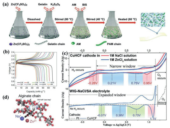
For example, Chen et al. reported a HPE consisting of zinc trifluoromethanesulfonate, water, potassium persulfate, acrylamide, and N, N'-methylenebisacrylamide (denoted as gelatin-g-PAM) [78]. An in-situ free radical polymerization method was used to prepare the HPE (Fig. 4a). The cross-linked HPE could survive extensive damage tests, which included hammering, sewing, and punching, owing to its outstanding mechanical strength. As a result, ZIBs based on the HPE showed significant potential for use in wearable batteries and outperformed the voltaic battery in practical applications. More importantly, the evaporation of water in the gelatin-g-PAM electrolyte was reduced because of the existence of a large number of amide bonds. In addition, the high viscosity of the HPE allowed it to stick tightly to the electrodes while the use of a bisalt (Zn/K salts) electrolyte system improved the ionic conductivity of the HPE (2.04 × 10⁻³ S/cm of the HPE versus 1.90 × 10⁻³ S/cm of a gelatin electrolyte). A Zn//gelatin-g-PAM//Zn3[Fe(CN)6]2 full cell exhibited a relatively wide voltage window (0.8–2.4 V) and an ultraflat platform during discharging (the operating voltage was approximately 1.8 V, Fig. 4b). An AZIB based on the HPE showed an energy density of 120 Wh/kg. Similarly, Pan et al. reported a 2.1 V aqueous Na-Zn hybrid battery based on a "water-in-gel" (WiGE) GPE electrolyte (mass ratio of NaCl, ZnSO4·7H2O, sodium alginate (SA), and deionized water was 1:1:0.3:0.8) [79]. Neither the 1 M NaCl nor the 1M ZnCl2 exhibited the capacity of copper hexacyanoferrate (CuHCF) owing to the OER that occurred in the high-voltage zone during the charging process. This is because the reduction potential of Na is 2.25 V (versus Zn/Zn2+), which is beyond the ESW range of aqueous electrolytes (Fig. 4c). The strong polarity of the functional groups (i.e., OH and COO−) of the SA chains confined the free water owing to the formation of hydrogen bonds between the water molecules and the polar groups. Thus, more of the free water was stored within the WiGE instead of coming in direct contact with the front surface of the Zn anode. Therefore, the HER and OER were limited, and the ESW of the WiGE was as high as 2.72 V, which is much larger than that of a NaCl WiSE without SA (ESW of 1.01 V). The voltage for the intercalation of Na+ ions was higher in the WiGE. In addition, the Zn2+ and ZnCl42− ions cointercalated into the CuHCF cathode. The ionic conductivity (62.2 mS/cm) of the bisalt WiGE was also higher than that of the NaCl WiSE (9.23 mS/cm), because the three-dimensional fibrillar porous polymer network that formed in the WiGE acted as a highly efficient "pass-way" (coordination bonds between the Na+/Zn2+ ions and the functional groups of SA) for the dissolved cations (Fig. 4d).
Figure 4
Figure 4.
(a) The fabrication process of the gelatin-g-PAM electrolyte. (b) The voltage file of the HPE based AZIBs. Reproduced with permission [78]. Copyright 2020, Spinger. (c) The ESW of CuHCF in Na/Zn ion aqueous electrolytes. (d) Schematic illustration of the ion transportation in water-in-gel electrolyte. Reproduced with permission [79]. Copyright 2021, Wiley-VCH.
The cost of the PEs lies between those of aqueous electrolytes and WiSEs, and their excellent mechanical strength makes them suitable for use in flexible/wearable devices. PEs can expand the ESW of AZIBs because their water content is lower than that of aqueous electrolytes, and they exhibit stronger hydrogen bonds between the functional groups and the free water molecules. Nevertheless, a few problems remain to be solved, such as the low ionic conductivity of PEs as well as their high thermal and chemical stabilities and the charge transfer resistance of the solid electrochemical interphase (SEI). Increasing the water content and number of hydrogen bonds between the free water molecules and functional groups of the polymer chain, using multiple salts, and building an artificial interphase layer (AIL) for electrode protection are effective methods of addressing the above-stated problems.
3.3
Eutectic electrolytes
Eutectic solvents exhibit ion-dipole interactions between the eutectic components of the Lewis or Brønsted acids and bases, which contain anionic and/or cationic species. The intermolecular interactions include hydrogen bonds and Lewis acid-base interactions as well as other types of interactions (i.e., those involving the Keesom force, Debye force, and London dispersion force) [80, 81]. The chemical environment in eutectic electrolytes (EEs) is different from that of ionic liquid electrolytes containing functional additives and those with Zn salts in high concentrations (i.e., WiSEs). The EEs used are often a mixture of a ligand (i.e., ethylene glycol, urea, acetamide and N-methylacetamide), salt, and some additives (water, acetonitrile, fluoroethylene carbonate and ethylene glycol), which may affect the viscosity and conductivity of the EE in question [81-84]. Water is the most widely used additive because it can improve the solubility of the Zn salts and hence the ionic conductivity of the EE. The major intermolecular interactions in EEs are hydrogen bonds and Lewis acid-base interactions. EEs can improve the electrochemical performance for the following reasons: (1) The interactions between the free water molecules and intermolecular of the eutectic solvents can break the hydrogen bonds of the network of the free water molecules, because the solvent molecules often have a larger negative charge density than that of the oxygen atoms in the water. Hence, the free water molecules are more likely to form hydrogen bonds with the solvent molecules instead of the other water molecules; (2) Owing to the low water content, the number of free water molecules is also limited; (3) The solvation sheath of the Zn ions is modified because of the presence of fewer water molecules, resulting in a decrease in the desolvation energy. The ligands including urea [85], succinonitrile [86], ethylene glycol (EG) [87], methylsulfonylmethane (MSM) [88] have been introduced in constructing EEs.
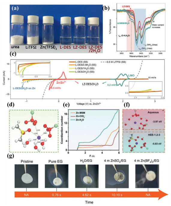
The interactions between an eutectic solvent and the free water were investigated by Zhao et al., who used a deep-eutectic solvent (DES) electrolyte with two salts (LiTFSI and Zn(TFSI)2) and controlled the amount of water (electrolyte denoted as LZ-DES/H2O) [85]. The DES electrolyte was synthesized at ambient temperature using a Li/urea molar ratio of 1:3–1:1.38, while the Li/Zn ratio was 20:1 (Fig. 5a). The controllable additive used (water) decreased the viscosity and increased the ion conductivity of the DES electrolyte. FTIR results showed a characteristic peak related to the chemically bonded water (the νas mode), which indicated that the slightly inducing of water in the DES (< 6.18%) would not cause the aggregation of the free water molecules (Fig. 5b). These molecules were bonded to the TFSI− ions and urea, as confirmed by 17O NMR measurements and MD simulations. Owing to the breaking of the free-water network, the ESW of LZ-DES/2H2O (water content of 6.18%) increased to 3.0 V (Fig. 5c), and a Zn//LZ-DES/2H2O//LiMn2O4 AZIB delivered an average voltage of 1.92 V and energy density of 52 Wh/kg based on the total weight of the pouch cell.
Figure 5
Figure 5.
(a) The stoichiometric amount of urea, Zn(TFSI)2 LiTFSI to fabricate L-DES, LZ-DES and LZ-DES/H2O. (b) The waterfall plot of IR bands within the range of 2900–3900 cm−1 with gradient water content in LZ-DES. (c) The ESW of LZ-DES based electrolytes with gradient water contents and aqueous electrolytes. Reproduced with permission [85]. Copyright 2019, Elsevier B.V. (d) The MD models of HEE-1.2–3. (e) RDFs for Zn-O (H2O), Zn-O (ClO4−), and Zn-O (MSM) and coordination number. (f) The binding energy of Zn2+-solvation structure in aqueous and HEE-1.2–3 electrolytes. Reproduced with permission [88]. Copyright 2022, Wiley-VCH. (g) Ignition tests of glass fiber separator saturated with different electrolytes. Reproduced with permission [89]. Copyright 2022, Spinger Nature.
Meanwhile, the Zn2+ solvation-sheath structure in a methylsulfonylmethane (MSM), zinc perchlorate, and water hydrated eutectic electrolyte (HEE) were studied by Han et al. [88]. Based on the viscosity, ionic conductivity, and thermodynamic stability of the HEE with a gradient water content, Zn(ClO4)2·6H2O: MSM: H2O with a molar ratio of 1.2:3.6:3 (denoted as HEE-1.2–3) was chosen as the optimal electrolyte. Its Raman and FTIR spectra confirmed that, with a decrease in the water content, the water gradually dropped out of the Zn2+ solvation shell, and the bulk water molecules were eliminated because of the weakening of the hydrogen bonds between them. In addition, the peak related to ClO4− vibrations in the FTIR spectrum split into two, one positioned at approximately 1088 cm−1 and the other at 1112 cm−1 (attributable to the Zn2+-ClO4− ion pair and ClO4− free anions, respectively), indicating the transformation of the Zn2+ ion solvation sheath (Fig. 5d). MD and DFT simulations further confirmed that the solvation sheath in HEE-1.2–3 was different from than in the aqueous electrolyte. One SMS replaced the water molecular to participate in the inner solvation sheath of the Zn2+ ions. The radical distribution functions (RDFs) indicated the formation of Zn-H2O and Zn-MSM in the HEE-1.2–3 electrolyte model, and their average coordination numbers in the inner hydration layer were 3.5 and 1.2, respectively (Fig. 5e). The binding energy of Zn-H2O was much lower than that of Zn-MSM (−4.51 eV versus −5.39 eV), indicating that the Zn plating process in HEE-1.2–3 was more stable than that in the aqueous electrolyte. As a result, the electrochemical performances of both the Zn anode and a full cell were higher when the former electrolyte was used (Fig. 5f).
In addition, in contrast to conventional liquid electrolytes, the physicochemical properties of eutectic electrolytes are affected by the type of Zn salt and ligand molecule used and their contents. A nonflammable hydrous organic electrolyte consisting of Zn(BF4)2, ethylene glycol, and water was reported by Han et al. [89]. As shown in Fig. 5g, the glass fiber separator used is nonflammable. However, as it was saturated with an organic electrolyte (i.e., EG), it immediately caught on fire when exposed to a flame. When Zn(BF4)2 was added to EG/H2O, however, the separator did not ignite even the EG content was high; this was owing to the flame retardance effect of Zn(BF4)2. In contrast, ZnSO4 was ineffective in preventing the separator from catching fire, although the water content in the ZnSO4/EG system was much higher than that of the Zn(BF4)2/EG electrolyte. In addition, the boiling and flash points of EG are also high, and this further enhanced the safety of the Zn(BF4)2/EG electrolyte with respect to practical applications.
In summary, EEs are promising electrolytes for use in high-voltage AZIBs, because they can expand the ESW of AZIBs to the same degree as WiSEs at a fraction of the cost. In addition, the ionic conductivity of EEs is higher than that of PEs. Moreover, the physicochemical properties of EEs can be modified based on the choice of the solvent, solvend, and additives used to ensure that AZIBs exhibit a low freezing point and high evaporation/flash points.
3.4
Dual-cation electrolyte
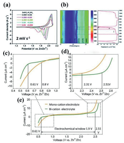
Dual-cation electrolytes for AZIBs consist of a Zn salt and other metal-cation salts, including Li- [90], Na- [91, 92], K- [93], Al- [94] and Mg-based [95] salts. The cation-insertion potential of the metal-cation salts added is higher than that of Zn2+, and their insertion in the cathode as charge carriers can increase the operating voltage of Zn hybrid aqueous batteries (ZHABs). Moreover, the presence of additional charge carriers in the electrolyte can improve the charge transfer kinetics of AZHBs, especially since most of the cations added are monovalent. In contrast to Zn2+ ions, monovalent ions exhibit weak electrotactic interactions during the solid-state diffusion process. Thus, their insertion is faster and more reversible. Interestingly, the operating voltage and reaction mechanism depend not only on the type of cations added but also their content. For example, Huang et al. reported a 1.9 V ZHAB with a K-Zn hybrid electrolyte [93]. The results of cyclic voltammetry (CV) of the Zn//ZnCHF ZHAB with electrolytes with different ratios of Zn/K ions suggested that increasing the Zn/K ratio shifted the first cathodic peak to a lower voltage but increased the second cathodic peak and current density (Fig. 6a). It was inferred that the insertion of K+ ions induced the first cathodic peak. The electrochemical mechanism of Zn-K ZHBA was obviously influenced by the Zn/K ion ratio. Using in-situ X-ray diffraction (XRD) analysis, the relationship between the insertion mechanism of the Zn2+/K+ ions and their ratio in the electrolyte was investigated. It was proved that with the increasing concentration of K+ from 0.05 M to 0.25 M in 0.5 M ZnSO4 electrolyte. The shifting behavior of the diffraction peaks was more similar to that in pure K2SO4 electrolyte (Fig. 6b), indicating that the K+ insertion/extraction was more thermodynamic favorable in the 0.5 M ZnSO4 + 0.25 M K2SO4 hybrid electrolyte. The CV curve also exhibited a higher redox potential of K+ insertion in the hybrid electrolyte than that in the pure ZnSO4.
Figure 6
Figure 6.
(a) The CV of the Zn//ZnCHF ZHABs with different Zn/K ratio of electrolyte. (b) 2D XRD pattern and the voltage file of the ZnHCF cathode in 0.5 M ZnSO4 + 0.25 M K2SO4 electrolyte during charge/discharge process. Reproduced with permission [93]. Copyright 2020, The Royal Society of Chemistry. (c–e) ESW of the Zn-Al hybrid electrolyte. Reproduced with permission [87]. Copyright 2020, American Chemical Society.
Dual-cation electrolytes are often used synergistically with WiSE and eutectic electrolytes as well as PEs and decoupling electrolytes to increase the ionic conductivity and modify the solvate-sheath structure of Zn2+ ions. Their individual contributions in broadening the ESW of aqueous electrolytes have not been studied extensively, and the effects of the additive cations on the ESW remain unclear. Li et al. reported a 1 M Al(CF3SO3)3/1 M Zn(CF3SO3)2 aqueous electrolyte with an expanded ESW for Zn/MnO2 AZIBs [94]. Compared to the ESW of monocation electrolytes, that of the bication electrolyte was wider, ranging from 1.5 V to 1.9 V (Figs. 6c–e). This can be attributed to a decrease in the potential for the HER from 0.8 V to 0.61 V and an increase in the potential for the OER from 2.31 V to 2.50 V. The involvement of the Al3+ ions in the solvate-sheath structure of the Zn2+ ions may have increased the oxidative stability compared with that when the molecules were in their free state, thereby inhibiting the HER and OER [96, 97].
The individual effect of dual-cation electrolytes on the ESW of AZIBs is limited, and the solvation environment of the Zn2+ ions after the addition of other cations has not been studied extensively. However, owing to the higher insertion potential of the added cations and the increase in the number of charge carriers in the electrolyte, dual-cation electrolytes are often used for modifying the electrolytes employed in AZIBs.
3.5
Decoupling electrolytes
Zn-Mn alkaline batteries have been available commercially for decades. The alkaline electrolyte ensures the high reversibility of the Zn/Zn(OH)42− reaction, shown in Eq. 6. However, the cathode reaction is hindered by the formation of a byproduct (i.e., Mn(OH)2). Mildly acidic electrolytes suitable for AZIBs have attracted considerable attention because they exhibit improved Zn2+, H+ and Li+ insertion/extraction mechanisms. On the other hand, according to the Pourbaix diagram of water (Fig. 2a), Zn corrosion and the HER at the anode side are more likely to occur at a lower pH, thereby resulting in a narrower ESW. This limits the cathode redox reaction involving the formation of Mn4+/Mn3+ and hence the operating voltage and specific capacity. Therefore, the decoupling electrolyte system is used to ensure that the cathode and anode experience the appropriate alkaline/acidic environment such that the potential of AZIBs, namely, a high operating voltage and energy density, are realized. The advantages of decoupling zinc metal batteries (DZMBs) over AZIBs can be summarized as follows: (1) The Mn2+/MnO2 cathode delays the OER in the acidic environment while the Zn(OH)42−/Zn anode suppresses the HER in the acidic electrolyte, thus expanding the ESW of the DZMBs. (2) Owing to the expanded ESW, MnO2 undergoes a two-electron transfer reaction, which ensures that Zn-Mn DZMBs exhibit an ultrahigh theoretical capacity (617 mAh/g) and operating voltage (> 2.5 V).
DZMBs consist of an alkaline chamber (filled with an alkali-based electrolyte such as KOH) and an acid chamber (filled with an acid-based electrolyte such as H2SO4 or MnSO4) for the Zn anode (metallic Zn) and cathode, respectively. A cation-exchange membrane (CEM), anion-exchange membrane (AEM), and a central chamber filled with neutral electrolytes are placed between the two chambers to prevent the neutralization of the electrolytes.
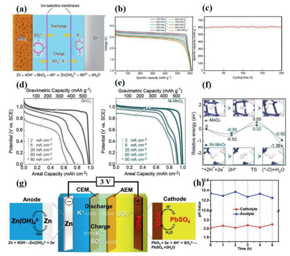
Zn-Mn DZMBs have attracted significant research interest recently [52, 53, 98]. Zhong et al. attempted to explain the working mechanism of DZMBs (Fig. 7a) [49]. They found that the manganese oxide dissolves from the cathode current collector in the electrolyte to form Mn2+ ions, and the Zn2+ ions react with the OH− ions to form soluble Zn(OH)42−. Meanwhile, the SO42− ions in the H2SO4 acid chamber and the K+ ions in the KOH alkali chamber diffuse to the neutral chamber in the middle. During the charging process, the Mn2+ ions in the acid chamber are deposited on the carbon felt while the Zn(OH4)2− ions in the alkali chamber are reduced to Zn on the Zn foil. The operating voltage of the DZMB was greater than 2.8 V (Fig. 7a) and much higher than those of a commercial lead-acid battery (2.0 V) and Zn-Mn AZIBs with a mildly acidic electrolyte (~1.3 V). In addition, owing to the two-electron transfer reaction (Mn4+/Mn2+), the specific capacity of the DZMB was 616 mAh/g at 0.1 A/g (Fig. 7b). Moreover, the DMZB exhibited an energy density of 1621.7 Wh/kg based on the mass of the MnO2 cathode as well as outstanding cycling stability even at a low cut-off voltage (1.0 V) for more than 200 h (Fig. 7c).
Figure 7
Figure 7.
(a) The schematic illustration of the Zn-Mn DZMB. (b) The voltage profile of Zn-Mn DZMB at current density of 100–1000 mA/g. (c) A 200 h continuous cycling test of Zn-Mn DZMB. Reproduced with permission [49]. Copyright 2020, Springrt Nature. The discharge curve of Zn-Mn DZMB (d) and Zn-Ni dopped Mn DZMB (e). (f) Relative energy profiles with the catalyzed electrolysis. Reproduced with permission [54]. Copyright 2020, Wiley-VCH. (g) Schematic illustration of the Zn-Pb DZMB. (h) The pH variation of catholyte and anolyte during cycling. Reproduced with permission [51]. Copyright 2020, Wiley-VCH.
However, although the Zn-Mn DZMB showed high energy density, its rate performance was unsatisfactory for large-scale applications (i.e., electric vehicles and cell phones). With respect to the anode side, the kinetics of the Zn(OH)42−/Zn redox pair are rapid (the standard rate, K0 = 2.5 × 10⁻⁴ cm/s) [99]. Hence, improving the kinetics of the MnO2 cathode is the key to increasing the rate performance of Zn-Mn DZMBs. Chao et al. reported the kinetics of catalyzed electrooxidation/ electroreduction electrolysis using NiSO4 as an addition for a H2SO4/MnSO4 cathodic electrolyte in a Zn-Mn DZMB [54]. Figs. 7d and e show the results of the conventional three-electrode-cell test performed to analyze the Mn2+/MnO2 redox reaction. The additive (NiSO4) obviously improved the specific capacity of the Zn-Mn DZMB, as the current density increased to 80 mA/cm2, and the specific capacity of the MnO2 cathode was only 0.65 mAh/cm2, which is much lower than that of a Ni-MnO2 battery (0.87 mAh/cm2). Meanwhile, the results of X-ray absorption fine structure (XAFS) analysis and DFT calculations proved that the valency of Mn in Ni-MnO2 was reduced from 3.91 to 3.78 while that of elemental Ni increased from +2 in the electrolyte to +3 in the Ni-MnO2 cathode. The Fourier transform of the extended X-ray absorption fine structure (EXAFS) results suggested that the presence of Ni increased the Mn and O vacancies in the Ni-MnO2 battery. The Ni-dopped MnO2 has more active electron states close to the Fermi level with greater charge delocalization; this accelerates the charge transfer and catalyzes the electrolysis dynamics. As a result, the reaction pathway forms on a lower-potential-energy surface with the codeposition of the Ni in MnO2 (Fig. 7f).
In addition to the Zn-Mn, Zn-Pb, and Zn-polyaniline systems [100], DZMBs with decoupling electrolytes have also been developed. Xu et al. produced a high-voltage Zn-Pb DZMB with an operating voltage of 2.9 V and current density of more than 2 mAh/cm2 (Fig. 7g) [51]. Free-standing PbO2 on Pb was used as the cathode material in a H2SO4 electrolyte, while Zn foil was used as the anode. More importantly, the changes in the pH of the catholyte and anolyte during the electrochemical process were analyzed (Fig. 7h). During the discharge process, the pH of the anolyte decreased while that of the catholyte increased, suggesting the consumption of protons at the cathode and the generation of hydroxide ions at the anode. The changes in the pH were reversed during the subsequent charging process, indicating that the Zn-Pb DZMB exhibited high reversibility.
In terms of the operating voltage, specific capacity, and energy density, DZMBs outperform other Zn metal batteries. However, their limited cycling life, high cost of the AEM and CEM, and complex fabrication process and battery design remain challenges. In addition, the Zn2+ solvent-sheath structure in the alkaline electrolyte has not been investigated extensively, which is essential for modifying the kinetics of Zn ions in alkaline electrolytes. Using a decoupling electrolyte in combination with a two-cation electrolyte or a eutectic electrolyte may further improve the electrochemical performance of DZMBs at a relatively low cost.
4.
Summary and perspectives
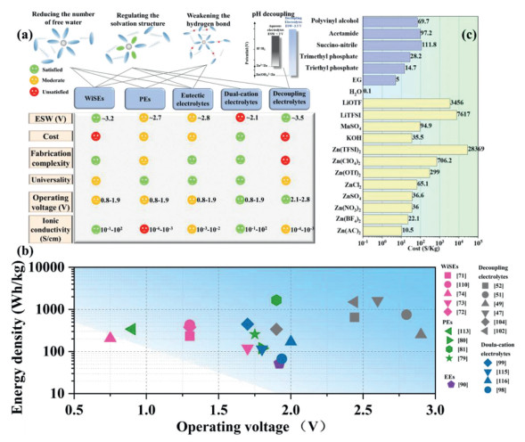
The properties of five different types of electrolytes for broadening the ESW of AZIBs, namely, WiSEs [101], PEs [102], dual-cation electrolytes [103], eutectic electrolytes [104], and decoupling electrolytes, were systematically summarized in this review. A few typical electrolytes of each type are listed in Table 1 along with their corresponding ESW, energy density, electrolyte formula, and operating voltage data. Next, the primary mechanisms of the five electrolyte systems, namely, WiSEs, PEs, eutectic electrolytes, dual-cation electrolytes, and decoupling electrolytes can be summarized as follows: (1) weaken the hydrogen bonds; (2) reduce the number of free water molecules; (3) regulate the solvation sheath of zinc ions; (4) decouple the anolyte and catholyte to create an alkaline/acidic environment for the Zn anode/cathode to suppress the HER and OER, respectively.
Table 1
Table 1.
The summary of the representative electrolytes with expanded ESW for high operating voltage zinc ion batteries.
These electrolytes can exhibit more than one modification mechanism, as shown in Fig. 8a. Based on the data listed in Table 1, it can be seen that WiSEs and eutectic electrolytes can significantly expand the ESW of aqueous electrolytes, resulting in ESWs as high as 3.2 V and 2.7 V, respectively. This is because these two types of electrolytes modify aqueous electrolytes significantly by directly reducing the number of free water molecules available; this is attributable to their lower water content. Meanwhile, they also weaken the hydrogen bonds formed between the free water molecules and regulate the solvation-sheath structure of the Zn2+ ions. On the other hand, the effect of PEs and dual-cation electrolytes on the ESW is not as pronounced, resulting in ESWs as high as 2.1 V and 2.5 V, respectively. Finally, the decoupling electrolytes have a significant advantage in broadening the ESW. Because of the lower redox potential of Zn(OH4)2− and given that the HER and OER are hindered in an alkaline/acidic electrolyte environment, these electrolytes result in ESWs as high as 3.5 V. More importantly, the two-electron transfer reaction of the Mn2+/MnO2 cathode means that this material outperforms other cathode materials in improving the operating voltage, specific capacity, and energy density. However, the cost factor cannot be ignored, as both the CEM and AEM are expensive (for example, according to Sigma-Aldrich, the price of a Nafion-117 CEM is 13,548 $/m2). Similarly, based on the solvents and solvends used commonly for the aqueous electrolytes employed in AZIBs, the cost of WiSEs is much higher than that of the other electrolytes. This is because LiTFSI and LiOTf as well as expensive Zn salts are used in large amounts in WiSEs. On the other hand, dual-cation electrolytes are the cheapest because of the low concentration and cost of the salts used. In addition, the fabrication process of DZMBs is also more complex. As discussed above, two or three chambers/tanks are needed for the decoupling of the catholyte and anolyte, in addition to the AEM and CEM. As a result, DMZBs cannot be assembled readily into coin and pouch cells. In contrast, WiSEs, eutectic electrolytes, and dual-cation electrolytes can be produced by simply mixing the appropriate solvent with the appropriate solvend. Moreover, PEs, eutectic electrolytes, and dual-cation electrolytes also show greater universality and can be employed with a wider range of cathode materials. Typically, high ion conductivity and low viscosity of electrolyte can accelerate the ion transport but also accelerate the self-discharge AZIBs [105]. Obviously, the viscosity of the PEs is the highest among the five types of electrolytes. Owing to the additive of the ligands in the eutectic electrolyte, the viscosity in eutectic electrolytes is much higher than that of the liquid electrolytes (WISE, dual-cation electrolytes, decoupling electrolytes). The ionic conductivity of the PEs is 10−6–10−3 [106]. In Fig. 8b, the energy density and operating voltage of the as mentioned AZIBs with the modified electrolyte are summarized.
Figure 8
Figure 8.
(a) The evaluation of the different electrolyte strategies and the modification mechanisms corresponding to these electrolytes. (b) Energy density-operating voltage plot of the AZIBs in Table 1. (c) The comparison of the commonly applied salts and the solvent of the electrolyte of AZIBs. The data were taken from https://www.sigmaaldrich.com on 23 March 2022. The yellow bulks are the salts and purple bulks are the additives, ligands and polymers for fabricating electrolytes for AZIBs.
We propose the following solutions for overcoming the problems related to the use of the above-discussed electrolytes with the aim of realizing high-voltage AZIBs.
Dual-cation solvents are often used with PEs, WiSEs, and eutectic electrolytes. This is because the use of a dual-cation electrolyte can increase the ionic conductivity and improve the kinetics of the Zn ions. To further widen the ESW of the electrolyte, a more synergistic approach should be adopted with respect to the five types of electrolytes mentioned above. In addition, novel electrolytes should be developed to expand the ESW of aqueous electrolytes.
The cost associated with electrolyte design should not be ignored (Fig. 8c). A few of the commonly applied solvents are too costly for AZIBs, which have been proposed as low-cost substitutes for commercial LIBs. The use of expensive salts and solvends will hinder the commercialization of AZIBs. Thus, only raw materials that are cheap should be considered for use in practical AZIBs.
Standardized electrochemical tests should be employed for evaluating the performance of the electrolytes used in AZIBs. In particular, the cut-off current density should be measured during linear sweep voltammetry (LSV) to determine the ESW and cut-off voltage. In addition, the current collector used in the CE test to evaluate the Zn plating/stripping process should be standardized [63]. The use of a standardized testing protocol would allow different AZIBs to be compared with ease.
While there have been several studies to match electrolytes with a high ESW with low-operating-voltage cathode materials (i.e., vanadate oxides and organics), it would be more meaningful to use high-operating-voltage cathode materials instead to evaluate the practical applicability of the electrolytes modified using the approaches reviewed in this paper.
Novel cathode materials and redox pairs with high operating voltages should be developed for further expanding the ESW of electrolytes. The choice of high-voltage cathode materials is limited to PBAs, a few Mn/V compounds (such as LiMn2O4 [85] and VOPO4 [107, 108]), polyanilines, decoupling systems, MXenes (Nb2CTx) [109] and MOFs (MnBTC-MOF) [110]. While electrolytes with an expanded ESW continue to attract significant research interest, the development of high-voltage cathode materials seems to have stalled. Hence, more attention should be paid to the development of novel cathode materials and redox pairs with a high working potential. In-situ oxidation cathodes and novel DMZB redox pairs have significant potential for use as high-operating-voltage cathode materials.
Declaration of competing interest
The authors declare that they have no known competing financial interests or personal relationships that could have appeared to influence the work reported in this paper.
Acknowledgments
This work was financially supported by Shenzhen Fundamental Research Programs (Nos. JCYJ20190809143815709 and JCYJ20200109141216566), Guangdong Natural Science Foundation (No. 2021A1515010412), the China Scholarship Council (CSC), and Shenzhen Key Laboratory of Advanced Energy Storage (No. 202204013000060).
[1]
G. Harper, R. Sommerville, E. Kendrick, et al., Nature 575 (2019) 75–86. doi: 10.1038/s41586-019-1682-5
Figure 1
(a) Number of scientific peer-reviewed publications and citations on AZIBs. Data were collected in May 2022 from clarivate web of science. (b) Comparison of energy density and power density of different secondary batteries [6, 23-25]. (c) Comparison of operating voltage and specific capacity of different secondary batteries. (d) The electrochemical stability window of the aqueous electrolytes of AZIBs [26-28]. (e) Schematic illustration of scoring the goal of fabricating high voltage AZIBs through the electrolytes engineering and developing high-voltage cathodes developing.
Figure 2
(a) Pourbaix diagram of water. (b) Pourbaix diagram of the Zn/H2O diagram. Reproduced with permission [58]. Copyright 2010, Springer. (c) Schematic illustration of zinc ions transportation and issues of AZIBs caused by free water.
Figure 3
(a) Snapshot of the MD simulation cell for HCZE (1 m Zn(TFSI)2 + 20 m LiTFSI) and the zinc-ions-solvation structures in the 1 m Zn(TFSI)2 + 5, 10 and 20 m LiTFSI. Reproduced with permission [70]. Copyright 2018, Nature Springer. (b) Schematic illustration of RDIBs. (c) CV curves measured in 5, 10 and 30 m ZnCl2 electrolytes. (d) CV curves of the Fc/C anode and Zn3[Fe(CN)6]2 cathode in ZnCl2 electrolytes with different concentrations. Reproduced with permission [40]. Copyright 2019, American Chemical Society. (e) FTIR spectra of the absc-electrolytes. (f) The relationship between the salt concentration and the ionic conductivity of acetate-based WiSE. (g) Zn2+conductivity of the acetate-based WiSE. Reproduced with permission [72]. Copyright 2020, Elsevier B.V.
Figure 4
(a) The fabrication process of the gelatin-g-PAM electrolyte. (b) The voltage file of the HPE based AZIBs. Reproduced with permission [78]. Copyright 2020, Spinger. (c) The ESW of CuHCF in Na/Zn ion aqueous electrolytes. (d) Schematic illustration of the ion transportation in water-in-gel electrolyte. Reproduced with permission [79]. Copyright 2021, Wiley-VCH.
Figure 5
(a) The stoichiometric amount of urea, Zn(TFSI)2 LiTFSI to fabricate L-DES, LZ-DES and LZ-DES/H2O. (b) The waterfall plot of IR bands within the range of 2900–3900 cm−1 with gradient water content in LZ-DES. (c) The ESW of LZ-DES based electrolytes with gradient water contents and aqueous electrolytes. Reproduced with permission [85]. Copyright 2019, Elsevier B.V. (d) The MD models of HEE-1.2–3. (e) RDFs for Zn-O (H2O), Zn-O (ClO4−), and Zn-O (MSM) and coordination number. (f) The binding energy of Zn2+-solvation structure in aqueous and HEE-1.2–3 electrolytes. Reproduced with permission [88]. Copyright 2022, Wiley-VCH. (g) Ignition tests of glass fiber separator saturated with different electrolytes. Reproduced with permission [89]. Copyright 2022, Spinger Nature.
Figure 6
(a) The CV of the Zn//ZnCHF ZHABs with different Zn/K ratio of electrolyte. (b) 2D XRD pattern and the voltage file of the ZnHCF cathode in 0.5 M ZnSO4 + 0.25 M K2SO4 electrolyte during charge/discharge process. Reproduced with permission [93]. Copyright 2020, The Royal Society of Chemistry. (c–e) ESW of the Zn-Al hybrid electrolyte. Reproduced with permission [87]. Copyright 2020, American Chemical Society.
Figure 7
(a) The schematic illustration of the Zn-Mn DZMB. (b) The voltage profile of Zn-Mn DZMB at current density of 100–1000 mA/g. (c) A 200 h continuous cycling test of Zn-Mn DZMB. Reproduced with permission [49]. Copyright 2020, Springrt Nature. The discharge curve of Zn-Mn DZMB (d) and Zn-Ni dopped Mn DZMB (e). (f) Relative energy profiles with the catalyzed electrolysis. Reproduced with permission [54]. Copyright 2020, Wiley-VCH. (g) Schematic illustration of the Zn-Pb DZMB. (h) The pH variation of catholyte and anolyte during cycling. Reproduced with permission [51]. Copyright 2020, Wiley-VCH.
Figure 8
(a) The evaluation of the different electrolyte strategies and the modification mechanisms corresponding to these electrolytes. (b) Energy density-operating voltage plot of the AZIBs in Table 1. (c) The comparison of the commonly applied salts and the solvent of the electrolyte of AZIBs. The data were taken from https://www.sigmaaldrich.com on 23 March 2022. The yellow bulks are the salts and purple bulks are the additives, ligands and polymers for fabricating electrolytes for AZIBs.

 DownLoad:


 下载:
下载:


