College of Materials Science and Engineering, Co-Innovation Center of Efficient Processing and Utilization of Forest Resources, Nanjing Forestry University, Nanjing 210037, China
Received Date:
27 April 2022 Accepted Date:
07 June 2022 Revised Date:
20 May 2022 Available Online:
15 February 2023
Abstract:
Li metal has been regarded as the holy grail for the next-generation Li-ion battery. Li dendrites issues, however, impede its practical application. In general, prolonging the sand time of Li nucleation and regulating homogeneous Li+ flux are effective approaches to suppress the dendrites formation and growth. Regarding this view, a functional polypropylene (PP) separator is developed to regulate ion transportation via a newly designed Li-based metal-organic framework (Li-MOF) coating. The Li-MOF crystallizes in the orthorhombic space group P212121 and features a double-walled three-dimensional (3D) structure with 1D channels. The well-defined intrinsic nanochannels of Li-MOF and the steric-hinerance effect both restrict free migration of anions, contributing to a high Li+ transference number of 0.65, which improve the Sand time of Li nucleation. Meanwhile, the Li-MOF coating with uniform porous structure promotes homogeneous Li+ flux at the surface of Li metal. Furthermore, the Li-MOF coating layer helps to build solid-electrolyte interphase (SEI) layer that comprises of inorganic LiF and Li3N, which further prohibits the dendrites growth. Consequently, a highly stable Li plating/stripping cycling for over 1000 h is achieved. The functional separator also enables high-performance full lithium metal cells, the high-rate and long-stable cycling performance of LiNi0.8Mn0.1Co0.1 (NMC811)-Li and LiCoO2 (LCO)-Li cells further demonstrate the feasibility of this concept.
Lithium metal has been considered as the holy grail for next-generation lithium batteries due to its high specific capacity (3860 mAh/g) and low redox potential (−3.05 V vs. SHE) [1-6]. Li dendrites growth induced by inhomogeneous Li plating/stripping, however, causes serious safety concerns and prohibits its practical applications [7-9]. Moreover, the low coulombic efficiency, originated from a severe Li/electrolyte reaction and an infinite volume change, results in impedance increasement and rapid capacity degradation [10-13]. Generally, the formation kinetics of lithium dendrites including the initially nucleation process and laterally growth process. The nucleation of dendrite starts at a so-called Sand's time during which the current density is above the over-limiting current [14]. The Sand's time is highly dependent on the transference number of Li+ (tLi), normally a larger tLi brings a higher Sand's time, leading to the longer lifetime prior to nucleation of lithium dendrites [15]. Therefore, the nucleation of lithium dendrites should be restricted by improving the tLi, that is promoting Li+ transport while retarding anions migration. For the growth process, the manipulation of homogeneous Li+ flux at the surface of Li metal is an effective way to avoid the randomly growth of mossy lithium dendrites [16]. In addition, the solid-electrolyte interphase (SEI) in situ formed on the Li metal surface in such electrolyte presents a porous structure with a nonuniform distribution of chemical components as well as Li+ flux [17]. During long-term cycling, the Li+ flux across the SE layer also shows crucial effect on the Li dendrites growth. It is concluded that the lithium dendrite issues could be well addressed by regulating the ion transport (both Li+ and anions) at the surface as well as in the SEI layer of Li metal.
Normally, an insulating porous separator is used to avoid the direct contact of cathode and anode, but allow the free transport of Li+ and anions transportation though the pores, which makes it an ideal candidate for regulating the ion transport after rational modification. Not only uniform nanoscale pore structure that induces homogeneous Li+ flux but also a cation selectivity that could limit the free transport of anions should be well designed. Regarding this, extensive efforts have been made on the traditional PP separators to regulate ion transport. Regarding this, solid-states electrolyte coated such as lithium lanthanum zirconium oxide (LLZO), Li1.3Al0.3Ge1.7(PO)4 (LAGP) [18, 19]. Two-dimensional layered graphene, nitrogen-doped graphene [20] and MXenes (Ti3C2Tx, Tx stands for functional groups), vertically aligned nanoscale channels [21], and 3D structures containing nanopores [22] have been designed to modulate the flux of Li+ transport. This functional coating materials may also in-situ react with Li metal and form uniform SEI layer that further uniform the Li+ flux during the dendrite growth, such as LiMg alloy (oriented from mesoporous MgO), Li3PO4 (reduced by Li1.3Al0.3Ti1.7PO4). The in-situ formed interphases not only uniforms the Li+ flux across the SEI layer but also suppress the dendrites growth because of its high modulus.
Recently, metal-organic frameworks (MOFs) [23-25], because of its controllable pore size, functional groups and various topological structures, have been widely evaluated as an ion modulator [26]. For example, a separator coated by MOFs was designed to suppress the shuttle effect of polysulfides. It was proved that the MOFs could inhibit the free movement of S2- [27]. Another kind of MOF material (Mn-BTC) constructed by 1, 3, 5-benzene tricarboxylate and manganese ions was also fabricated to prohibit the free diffusion of polysulfides via an electrostatic repulsion effect [28]. It is found that the MOFs are ideal candidates to suppress the free movements of S2- anion.
In this work, a functional separator coated with Li-MOF which possesses confined porous structure is fabricated after a rational design to regulate the Li+ transport for addressing the lithium dendrite issues. Firstly, the 1D channels of Li-MOF are divided into several small compartments by coordinated DMF molecules. These confined channels only allow small Li+ ions to pass through and thus restrict the free migration of larger PF6- anions. With the Li-MOF coated onto the commercial polypropylene (PP) separator, tLi increases from 0.36 to 0.65, indicating the improvement of Li+ transport and the restriction of anions migration. In addition, a relatively homogeneous Li-MOF coating with intrinsic nano-sized channels and gap channels (ca. 2 Å) could simultaneously achieve a uniform lithium deposition, which further suppresses the growth of lithium dendrites. Furthermore, the N(CH3)2 functional group in the Li-based MOF may react with Li metal and forms stable SEI layer. As a result, a highly stable Li plating/stripping (more than 1000 h) with uniform SEI layer is enabled by the multi-functional separator. Moreover, the electrochemical performance of both LiNi0.8Mn0.1Co0.1 (NMC811)-Li and LiCoO2 (LCO)-Li cells with the designed functional separator exhibit excellent electrochemical performance. For example, even at a high active material loading of 15 mg/cm2, the capacity retention of LCO-Li cell is 72.2% after 500 cycles at 1 C. Our work may offer new possibility and principles for designing not only advanced separators but also solid-state electrolytes toward high-energy-density dendrite-free Li metal batteries.
To synthesize Li-MOF, a mixture of LiCl (0.4 mmol) and isophthalic acid (0.2 mmol) was dissolved in the solution of 5 mL N, N-dimethylformamide dimethylformamide (DMF)/H2O (4:1, v/v). Then the mixture was treated by ultrasound to clear solution and heated at 80 ℃ for 4 days. The mixture was then cooled down to room temperature. Colorless square crystals were obtained and air-dried (yield 68%, based on LiCl). The coating of Li-MOF on PP separator was performed by a traditional slurry coating method. The receipt containing 90 wt% Li-MOF powders and 10 wt% PVDF binder was thoroughly mixed in 1-methyl-2-pyrrolidone (NMP) solvent. The well-dispersed slurry was cast on commercial polypropylene (PP, Celgard 2500) separators and then dried in a vacuum oven at 55 ℃ for 12 h. The coating thickness after drying was controlled to be below 15 µm. The used separators for Li-Li and full cells were double-side and single-side coating, respectively.
The crystal structure of the synthesized Li-MOF was characterized by X-ray diffraction (XRD) (Cu K, λ ~ 0.15406 nm). Morphologies of the Li-MOF and Li-MOF coated PP separator was examined using a field-emission scanning electron microscope (FESEM, JSM-7600F). Fourier-transform infrared spectroscopy (FTIR) was carried out to examine the chemical bond of MOF. X-ray photoelectron spectroscopy (XPS) was used to analysis the chemical bond of MOF as well as the SEI on Li metal after cycling. Thermogravimetric analysis (TGAs) was carried out on a Rigaku standard TG-DTA analyzer under N2 with a heating rate of 10 ℃/min, with an empty Al2O3 crucible used as the reference. Simulation of the PXRD pattern was carried out by single-crystal data. Differential scanning calorimetry (DSC) was characterized using a DSC250 Differential scanning calorimeter (TA, USA) with a heating rate of 10 ℃/min from 25 ℃ to 550 ℃ under N2 atmosphere.
A carbonate electrolyte containing 1 mol/L LiPF6 in mixed ethylene carbonate (EC): ethyl methyl carbonate (EMC): dimethyl carbonate (DMC) (1:1:1, v/v/v) solvents was used for all cells. Li-Li symmetric cells with PP and PP/MOF separators were prepared with current densities between 1−5 mA/cm2. Li/Cu cells with PP and PP/MOF separators were also assembled to test the lithium deposition overpotential. LCO-Li cells with an active material loading of ~15 mg/cm2 were fabricated and tested between 2.8-4.3 V. The LCO cathode contains 80 wt% LCO, 10 wt% polyvinylidene difluoride (PVDF) and 10 wt% carbon black. The long-life performance of LCO-Li cell was tested at a rate of 1 C (1 C = 140 mA/g). Rate capability tests at various current densities from 0.5 C to 4 C were performed. Electrochemical impedance spectroscopy (EIS) tests were performed using an electrochemical workstation (Biologic SP-300) between 7 MHz and 0.1 Hz with an AC amplitude of 10 mV. The NMC811-Li cells with an active material loading of ~10 mg/cm2 were fabricated and tested between 2.7−4.3 V at a current of 0.5 C (1 C = 200 mA/g). The NMC811 cathode contains 80 wt% LCO, 10 wt% PVDF and 10 wt% carbon black.
The relationship between ionic conductivity (σ) and temperature was measured by electrochemical impedance spectrum (EIS) analysis. The ionic conductivity of the composite electrolyte was characterized in a stainless steel (SS) sandwich (SS-Separator-SS) cell by Bio-logic electrochemical workstation in the frequency range from 7 MHz to 0.1 Hz at room temperature with an applied oscillation voltage of 10 mV. Prior to the measurement the system was kept at the specific temperature for 1 h. The ion conductivity (σ) was calculated via following formula: σ = L/(R × S), in which L was the thickness of the separator, R and S represented the bulk resistance and the area of the separator, respectively. Li/separator/Li symmetric cells were prepared to measure the tLi and polarization curves of the battery through alternating current (AC) impedance and direct current (DC) polarization methods. The value of tLi were calculated on the basis of the Bruce–Vincent–Evans formula: tLi = IS (ΔV - I0R0)/(ΔV - ISRS), where I0, IS, R0, RS represent the initial, steady-state polarization current, initial resistance and steady-state resistance, respectively.
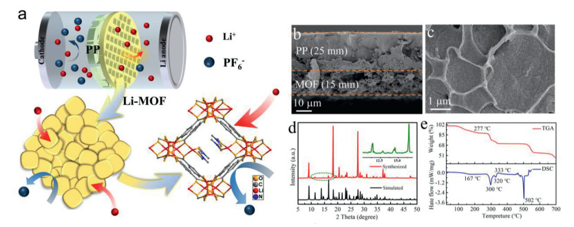
Herein, a new kind of Li-MOF with smaller channels was selected to prepare the PP/MOF composite separator based on considerations of the effects of steric hindrance. The functional Li-MOF material loaded on the surface of PP membranes is expected to improve the transport selectivity of lithium ions. This MOF material features a double-walled 3D porous structure with 1D channels. It is worth noted that there existing confined channels (ca. 2 Å) formed by division of the coordinated DMF molecules as illustrated in Fig. 1a. These confined channels may provide a pathway for lithium ions in the lithium battery. The as-synthesized Li-MOF was then hand grinded in a mortar for 30 min to get finely Li-MOF powders. The Li-MOF was coated on PP separator using a compatible slurry casting method with PVDF binder. The coated Li-MOF shows a hollow structure with a thickness of ~15 µm (Fig. 1b). The interconnected Li-MOF spheres exhibit a scale of ~1 mm, which is much smaller than that of PP separator. Also, the MOF samples are evenly distributed on the surface of PP separator (Fig. 1c). In addition, the intrinsic confined atomic channels of the MOF framework will further uniform the lithium ions transport. The crystal structure of as-prepared Li-MOF powders and PP/MOF separator were confirmed by X-ray diffraction (XRD). As shown in Fig. 1d, the XRD peaks of as-synthesized MOF were in good agreement with that of previously reported by our group [29]. There exist crystalline MOF materials (Fig. S1 in Supporting information) in the composite membrane. The slight shifts of low-angle peaks in the XRD patterns should be related to the dynamic sliding of the framework, which might be triggered by the grind mechanical pressure exerted on the material. Thermogravimetric analysis (TGA) and differential scanning calorimetry (DSC) experiments were also performed to test the thermal stabilities of the Li-MOF material. The curve shows two platforms from 100 ℃ to 600 ℃, the sample maintains its crystal integrity until ca. 490 ℃ (Fig. 1e), indicating the high thermal stability of the Li-MOF material. Furthermore, the DSC curve result is consistent with the temperature information provided by the thermogravimetric curve (Fig. 1e). These results indicate that the Li-MOF sample is an ideal candidate to prepare functional ions regulator.
Figure 1
Figure 1.
(a) Schematic illustration of the PP/MOF separator regulating the Li+ and anions transportation at the surface of Li metal. The crystal structure of the newly designed Li-MOF. (b) The cross-sectional SEM image of PP/MOF separator. (c) The surface SEM image of PP/ MOF separator. (d) XRD diffraction patterns of the as-synthesized Li-MOF. (e) The TGA and DSC curves of the fabricated Li-MOF.
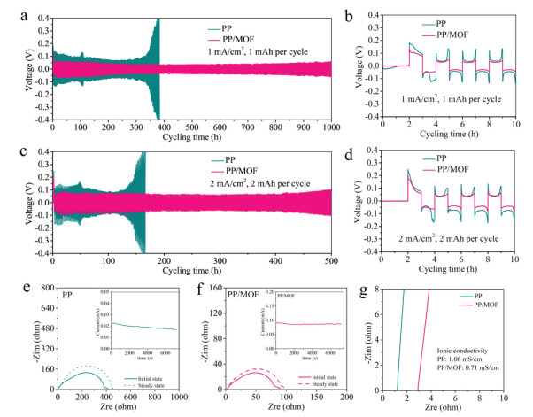
To estimate ion transportation and electrochemical stability of the Li-MOF coated PP separator against lithium metal, symmetric Li-Li coin-type cells were assembled and carbonate liquid electrolyte was added into the cells. With an area capacity of 1 mAh/cm2, the symmetric cells with PP/MOF separators demonstrate a stable Li plating/stripping voltage during 1000 h under a current density of 1 mA/cm2 (Fig. 2a). By contrast, the cell with the PP separator shows an obvious voltage increase after 350 h. This may be caused by continuous dendritic mossy Li and dead lithium formation during repeated cycles, which not only weakens physical contact with each other but also reduces the bulk conductivity of Li dendrite. At an enlarged view of the polarization voltage curves, shown in Fig. 2b, the PP/MOF separator shows much lower nucleation overpotential, because the sharp voltage change between the initial nucleation and the stable deposition process should be associated with the nucleation overpotential. In the case, the overpotentials of PP separator were 50, 70 and 78 mV for the first three cycles at 1 mA/cm2. By a sharp contrast, the overpotentials of PP/MOF separator were 15, 11, and 10 mV for the initial 3 cycles. At a higher area capacity of 2 mAh/cm2 per cycle, the same trend is also observed (Figs. 2c and d). The cell with PP/MOF shows stable cycling after 500 h, while the cell with the PP separator shows an obvious voltage hysteresis increase after 120 h. With the Li-MOF coating, the electrochemical stability of Li plating/stripping was significantly improved. To reveal the Li deposition mechanism with the Li-MOF coating, the Li+ transfer number tLi was evaluated quantitatively through the classical Bruce–Vincent model [8]. Generally, the PP and PP/MOF separators were assembled into the Li-Li symmetric cells, the polarization current under a small polarization voltage, the initial and steady-state values of the impedance were examined. As shown in Figs. 2e and f, the interfacial resistance of the PP/MOF separator was much smaller than that of the PP separator before and after polarization. Based on the above model, the tLi values of the PP and PP/MOF separators were 0.36 and 0.65, respectively. The enhanced tLi could be attributed to the confined channels of the Li-MOF, which shows steric-hinerance effect of the lager anions PF6− in liquid electrolyte. As shown in Fig. 2g, the ionic conductivity of the PP and PP/MOF separators was measured by electrochemical impedance spectroscopy (EIS) in stainless steel (SS)/Separator/SS cells. The PP and PP/MOF separators exhibited an ionic conductivity of 1.06 and 0.71 mS/cm, respectively. The relatively low ionic conductivity of PP/MOF may be associated with the nanopores and its prohibition of movement of the anions.
Figure 2
Figure 2.
(a) The cycling performance of Li-Li symmetric cell with PP and PP/MOF separators at a current density of 1 mAh/cm2. (b) The enlarged curve in (a) during the initial 10 h. (c) The cycling performance of Li-Li symmetric cell with PP and PP/MOF separators at a current density of 2 mAh/cm2. (d) The enlarged curve in (c) during the initial 10 h. (e) Current-time profile of the symmetrical Li-Li cell with PP separator. The inset shows the EIS of the Li-Li symmetric cell before and after polarization. (f) Current-time profile of the symmetrical Li-Li cell with PP/MOF separator. The inset shows the EIS of the Li-Li symmetric cell before and after polarization. (g) Impedance of SS-SS symmetric cells with PP and PP/MOF separators.
To further determine energy barrier of the Li nucleation before and after Li-MOF coating, impedance of Li-Li symmetric cells at varying temperatures from 30 ℃ to 60 ℃ were carried out (Fig. S2 in Supporting information). Figs. S2a and b show the impedance of PP and PP/MOF separators, respectively. The Arrhenius plot was shown in Fig. S2c, and the energy barriers for PP and PP/MOF were calculated to be 71.25 and 53.93 kJ/mol (Fig. S2c), respectively. The lower energy barrier for Li deposition induces smaller overpotential in the Li-Li symmetric cells. This phenomenon was further confirmed in a Li-stainless steel (SS) cell (Fig. S3 in Supporting information), at 1 mA/cm2, the nucleation overpotentials for PP and PP/MOF were 170 mV and 77 mV, respectively. It is obvious that the Li-MOF coating effectively reduces the Li nucleation energy barrier, which may attribute to the homogeneous Li+ flux regulation that reduces the local current density. In addition, the restricting of anions migration can also reduce the concentration polarization effect that leads to high-rate performance [8]. The unique structure of Li-MOF coating not only promotes the cycling stability but also enhances the rate performance in lithium metal battery (Fig. S4 in Supporting information), which is enabled by a simple and scalable Li-MOF coating method.
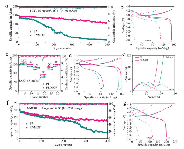
To further demonstrate the functional effects of PP/MOF separator, NMC811-Li and LCO-Li full cells were assembled. High area capacity LCO cathode with a mass loading of 15 mg/cm2 was used to evaluate the stability of the modified separator against Li metal. For a full LCO-Li cell, as shown in Fig. 3a, the cycling stability of the cell using PP/MOF was significantly improved. For example, with a voltage window of 2.8–4.3 V, the specific capacity retention of PP separator was only 11.6 mAh/g after 500 cycles at a current density of 1 C (1 C = 140 mA/g), which is 7.7% of the initial capacity (150.1 mAh/g). In a sharp contrast, the cell with PP/MOF still shows a high specific capacity of 109.5 mAh/g and the capacity retention ratio is 72.2%, which is almost 9 times enhanced than that without Li-MOF coating. The Li-MOF modification also reduces the overpotential in a full lithium metal cell, as shown in Fig. 3b, for the initial cycle, the overpotentials at the mid-capacity point of PP and PP/MOF were 16 and 8 mV, respectively. After 500 cycles, the overpotentials of PP and PP/MOF increased to 600 and 300 mV, respectively. The smaller overpotential may be associated with the fast kinetics during Li nucleation and lithium growth processes, which is enabled by the homogeneous Li+ flux and high Li+ transfer number. It should be noted that, the continuous SEI formation also contributes larger overpotential. However, in the case of PP/MOF separator, the stable cycling performance implies that the stable SEI should be formed with the existence of Li-MOF. The fast kinetics and stable SEI of Li dendrites contribute to high-rate performances. For example, the LCO/Li cell with PP/MOF separator exhibited good rate performance (Figs. 3c and d) and the specific capacities were 149.1, 133.4 and 91.8 mAh/g at 1, 2 and 4 C, respectively. For the PP separator, the rate capacities were only 138.7, 124.7 and 77.8 mAh/g at 1, 2 and 4 C, respectively. The impedance spectra further confirm the fast kinetic of Li deposition enabled by the MOF (Fig. 3e). For the as-assembled cells, one semicircle was observed for each spectrum, which is corresponded to the charge transfer resistance. It is obvious that the charge transfer resistance was reduced with the Li-MOF modification. After 100 cycles, a new semicircle was observed at high frequency, which is attributed to the SEI resistance. Again, the SEI resistance of the cell with PP/MOF separator was also smaller than that without Li-MOF coating. The EIS data directly demonstrates the fast Li+ transportation at the surface as well as the SEI layer with the Li-MOF modification. The PP/MOF functional separator could also be used in a lithium metal battery with high specific single-crystal NMC811 cathode. At a current density of 0.2 C (1 C = 200 mA/g) in a voltage window between 2.8−4.2 V, the initial specific capacities were 198.3 and 200.7 mAh/g for NMC811-Li cells with PP/MOF and PP separators (Fig. 3f), respectively. The current density was increased to 0.5 C after 2 cycles, the cell with PP/MOF separator shows higher capacity retention of 120 mAh/g compared to the 37.6 mAh/g of the cell with PP separator (Fig. 3g).
Figure 3
Figure 3.
(a) The cycling performance of LCO-Li cells with PP and PP/MOF separators. The loading is 15 mg/cm2, and the rate is 1 C (1 C = 140 mA/g). (b) The 1st and 500th charge-discharge profiles of LCO-Li cells in (a). (c) The rate performance of LCO-Li cells with PP and PP/MOF separators. (d) The charge-discharge profiles of the LCO-Li cells in (c). (e) The impedance of LCO-Li cells with PP and PP/MOF separators before cycling and after 100 cycles. (f) The cycling performance of NMC811-Li cells with PP and PP/MOF separators. The loading is 10 mg/cm2, and the rate is 0.5 C (1 C = 200 mA/g). (g) The 1st and 400th charge-discharge profiles of NMC811-Li cells in (f).
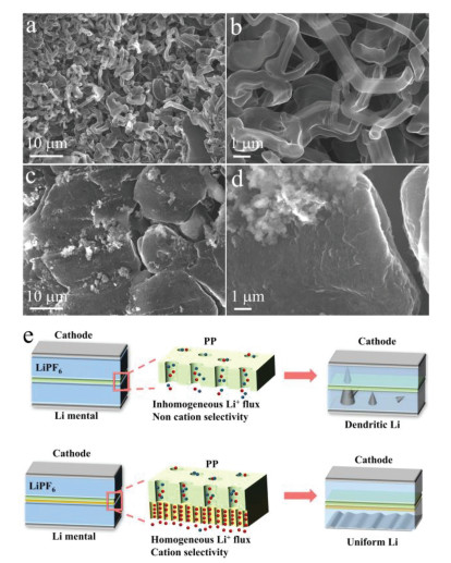
Both the homogenous Li+ flux and ionic selective effect of PP/MOF separator contribute to uniform Li deposition. The surface morphology of the deposited lithium after repeated Li plating/stripping processes were shown in Fig. 4, the lithium metal cycled in the cell with a PP separator shows a mossy and porous morphology (Fig. 4a). Besides, a large amount of dendritic and rod-like deposits could be observed on the surface of lithium metal (Fig. 4b). The transformation of Li metal to Li dendrites increases the surface area and unwanted side reactions with liquid electrolyte, which laterally increases the polarization voltage and causes fast capacity fading. In a sharp contrast, the surface of lithium metal after cycling in a PP/MOF cell exhibits relatively smooth and glossy morphology because of no lithium dendrites but some disc-like lithium metal formed (Figs. 4c and d). It is demonstrated that Li-MOF coating on PP separator is highly effective to construct dendrite-free Li metal anode. Meanwhile, the Li nucleation and dendrite growth is highly dependent on the sand time and Li+ flux. In theory, not only the intrinsic nanopores in Li-MOF that serves as Li transport channel but also the steric-hinerance effect of confined channels in Li-MOF that forbidden the free transportation of anions. As a result, a higher tLi leads to larger Sand's time (the nucleation time of lithium dendrites) according to the Sand's formula, implying the dendritic nucleation is suppressed. In addition, during the dendrite growth process, the nano-sized channels (ca. 2 Å) in Li-MOF promoted a uniform Li+ flux for a homogeneous Li deposition, which further suppressed the lithium dendrites.
Figure 4
Figure 4.
(a, b) The SEM image of cycled Li metal with PP separator at 1 mAh/cm2 after 10 cycles. (c, d) The SEM image of cycled Li metal with PP/MOF separator at 1 mAh/cm2 after 10 cycles. (e) The effect of Li-MOF ion regulator on the lithium metal deposition.
The Li-MOF also contributes to form stable SEI during Li plating and stripping. The Li-Li symmetric cell was disassembled after 100 cycles and the Li metal was washed with DMC before characterization. It is found that besides Li2CO3 (Fig. S5a in Supporting information) that formed by reducing the carbonate solvents, LiF and Li3N components were detected at the surface of cycled Li metal. For the F 1s spectrum, as showed in Fig. S5b (Supporting information), two distinct peaks of LiF (684.7 eV) and CF groups (687.1 eV) were observed. The inorganic LiF component was from the reduction of FEC, which shows stable property during repeated lithium plating and stripping processes [30, 31]. In the spectrum of N 1s (Fig. S5c in Supporting information), a distinct peak of Li3N at the binding energy of 398.8 eV was clearly observed. It should be mentioned that the formation of Li3N is one of important effects of N(CH3)2 groups in the Li-MOF framework. Because some Li-MOF residue was observed on the Li metal after cycling. This phenomenon indicates that Li-MOF peeled off from the PP substrate during the cell disassembling process due to the strong interaction between Li metal and Li-MOF. The Li3N can act as a highly conductive and mechanical robust SEI, because it shows an ionic conductivity of 10−3 S/cm [32], and relatively high Young's modulus of 150 GPa [33, 34]. The distinct advantages of Li3N as an SEI component have been demonstrated in the previous works [35]. The Li 1s spectrum (Fig. S5d in Supporting information) further confirms the inorganic components of LiF and Li3N, in which a main peak at 55.2 eV and a shoulder peak 55.7 eV were detected. To support the above XPS results, EDS mapping of the cycled Li metal was performed (Fig. S6 in Supporting information). The Li pillars have a size of several ten micron-meters, the distributions of C, F and N are almost the same shape of the Li pillars, implying the formation of LiF, Li3N and Li2CO3 on the surface. However, the relative intensities of F and N are much higher than that of C, revealing the main components of SEI are LiF, Li3N. These results demonstrate that the SEI layer in PP/Li-MOF separator composed of inorganics highly conductive and mechanical robust LiF and Li3N, which will help to suppress Li dendrites and uniform the Li+ flux at the interface between liquid electrolyte and Li metal (Fig. 4e). Consequently, not only uniform Li+ flux but also stable SEI layer achieved, which synergistically contributes to stable Li metal anodes.
By summary, to build high performance and dendrite-free Li metal anode, a multifunctional separator with Li-MOF coating was prepared to regulate Li+ transportation and form stable SEI toward. The well-defined intrinsic nanochannels in MOF framework and the steric-hinerance effect both restrict the free migration of anions. As a result, the high Li+ transference number suppresses the dendritic nucleation process. For the dendrite growth process, the nano-sized channels in MOFs promoted a uniform Li+ flux for a homogeneous Li deposition. Furthermore, a highly stable Li plating/stripping cycling for more than 1000 h was enabled by the Li-MOF coated PP separator. In addition, the PP/MOF separator could also be implemented in NMC811/Li and LCO/Li full cells and an improvement in the overall electrochemical performance including long-term cycling stability at high mass loading and excellent rate performance were achieved. We hope the separator modification strategy proposed here may provide the same effects to other alkali metal anodes (Na, K, Mg, etc.), which will boost the electrochemical performance of energy storage devices in portable electronics and electric vehicles.
Declaration of competing interest
The authors declare that they have no known competing financial interests or personal relationships that could have appeared to influence the work reported in this paper.
Acknowledgments
We gratefully acknowledge the financial support provided by the National Natural Science Foundation of China (Nos. 21971113, 22175094, 51902165), the Natural Science Foundation of Jiangsu Province (No. BK20200800), Independent Innovation of Agricultural Science and Technology in Jiangsu Province (No. CX(21)3163), Natural Science Foundation of the Jiangsu Higher Education Institutions (No. 20KJA150001).
Supplementary materials
Supplementary material associated with this article can be found, in the online version, at doi:10.1016/j.cclet.2022.06.017.
[1]
X. B. Cheng, R. Zhang, C. Z. Zhao, Q. Zhang, Chem. Rev.117 (2017) 10403–10473. doi: 10.1021/acs.chemrev.7b00115
X. Li, F. E. Kersey-Bronec, J. Ke, et al., ACS Appl. Mater. Interfaces 9 (2017) 16071–16080. doi: 10.1021/acsami.6b16773
[35]
H. H. Sun, A. Dolocan, J. A. Weeks, et al., J. Mater. Chem. A7 (2019) 17782–17789. doi: 10.1039/c9ta05063a
Figure 1
(a) Schematic illustration of the PP/MOF separator regulating the Li+ and anions transportation at the surface of Li metal. The crystal structure of the newly designed Li-MOF. (b) The cross-sectional SEM image of PP/MOF separator. (c) The surface SEM image of PP/ MOF separator. (d) XRD diffraction patterns of the as-synthesized Li-MOF. (e) The TGA and DSC curves of the fabricated Li-MOF.
Figure 2
(a) The cycling performance of Li-Li symmetric cell with PP and PP/MOF separators at a current density of 1 mAh/cm2. (b) The enlarged curve in (a) during the initial 10 h. (c) The cycling performance of Li-Li symmetric cell with PP and PP/MOF separators at a current density of 2 mAh/cm2. (d) The enlarged curve in (c) during the initial 10 h. (e) Current-time profile of the symmetrical Li-Li cell with PP separator. The inset shows the EIS of the Li-Li symmetric cell before and after polarization. (f) Current-time profile of the symmetrical Li-Li cell with PP/MOF separator. The inset shows the EIS of the Li-Li symmetric cell before and after polarization. (g) Impedance of SS-SS symmetric cells with PP and PP/MOF separators.
Figure 3
(a) The cycling performance of LCO-Li cells with PP and PP/MOF separators. The loading is 15 mg/cm2, and the rate is 1 C (1 C = 140 mA/g). (b) The 1st and 500th charge-discharge profiles of LCO-Li cells in (a). (c) The rate performance of LCO-Li cells with PP and PP/MOF separators. (d) The charge-discharge profiles of the LCO-Li cells in (c). (e) The impedance of LCO-Li cells with PP and PP/MOF separators before cycling and after 100 cycles. (f) The cycling performance of NMC811-Li cells with PP and PP/MOF separators. The loading is 10 mg/cm2, and the rate is 0.5 C (1 C = 200 mA/g). (g) The 1st and 400th charge-discharge profiles of NMC811-Li cells in (f).
Figure 4
(a, b) The SEM image of cycled Li metal with PP separator at 1 mAh/cm2 after 10 cycles. (c, d) The SEM image of cycled Li metal with PP/MOF separator at 1 mAh/cm2 after 10 cycles. (e) The effect of Li-MOF ion regulator on the lithium metal deposition.

 DownLoad:

 下载:
下载:


