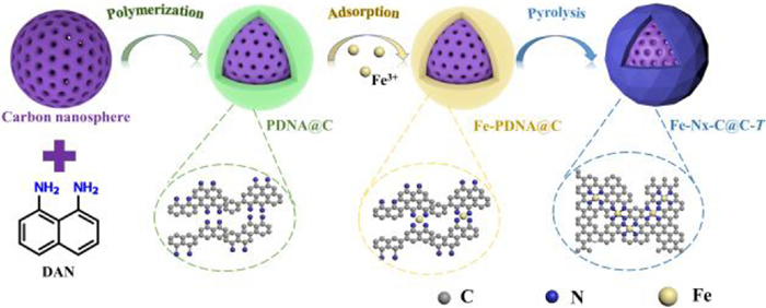
Scheme 1.
Illustration for the synthesis of Fe-Nx-C@C-T catalysts.
Polymer-chelation approach to high-performance Fe-Nx-C catalyst towards oxygen reduction reaction
Xue Wang , Li Zhang , Meiling Xiao , Junjie Ge , Wei Xing , Changpeng Liu , Jianbing Zhu

The electrochemical energy conversion and storage technologies, i.e., fuel cells and metal-air batteries, are of significant importance to pursue a sustainable and clean future. The key to enable the widespread commercialization of these technologies is the development of cost-effective and high-performance electrocatalysts for the sluggish oxygen reduction reaction (ORR). Although Pt-based catalysts are regarded as the most efficient one, the high cost and scarcity of Pt severely impede their practical deployment. In this regard, great efforts have been devoted to searching for non-precious metal alternatives, including transition metal macrocyclic compounds-based catalysts [1-3], pyrolyzed transition metal, nitrogen co-doped carbons (M-Nx-C) [4-6], metal-free heteroatom-doped carbon materials [7-9] and transition-metal chalcogenides [10, 11]. Among the various non-precious metal catalysts (NPMCs), M-Nx-C has attracted the most attention due to the higher activity and stability.
The past decades have witnessed the development of M-Nx-C electrocatalysts from trial-and-error research to mechanism guided design. Initially, random combination of carbon precursors, nitrogen-containing species and metal salts was employed to prepare M-Nx-C catalysts, and the synthetic process was adjusted based on performance feedback mode [12-14]. With the help of advanced characterization techniques, the active site structure was identified as metal-nitrogen coordinates (M-Nx) and a coherent picture of structure–activity relationship was built, where Fe-Nx exhibits the highest intrinsic activity [15-17]. Since then, the research interests are oriented to prepare Fe-N-C catalysts with dominated Fe-Nx sites. As the Fe-Nx was proposed to form in the micropore of carbon substrate [18, 19], microporous metal-organic frameworks (MOFs)-assisted strategy has been developed for the synthesis of Fe-Nx-C catalysts [20-22]. Although it benefits the preferential growth of atomically dispersed Fe-Nx sites without the formation of inactive iron aggregates, the micropore is unfavorable for mass transfer and the active sites buried inside the carbon matrix are inaccessible by reactants, resulting in the incomplete expression of the intrinsic activity. Besides, the predominated disordered-packing carbon atoms of MOF-derived catalysts would hinder the rapid electron transport along the Fe-Nx-C catalysts. Therefore, alternative approaches to Fe-Nx-C catalysts with highly accessible Fe-Nx sites and excellent electronic conductivity are urgently desirable.
Featured with rich nitrogen content, poly-1, 8-diaminonaphthalene (PDAN) has been developed as N, C precursor for the preparation of N-doped carbons in our previous study [23]. The derived carbon materials exhibit hierarchically porous structure, facilitating oxygen diffusion and water removal. Besides, the N dopants can serve as anchoring sites for the deposition of atomic Fe and thus form the active Fe-Nx sites. Inspired by this, we herein report a polymer-chelation strategy utilizing PDAN-Fe(Ⅲ) cheating complex as precursor for the synthesis of Fe-Nx-C catalyst. The in-situ formed Fe-Nx active sites are uniformly deposited onto the surface of the commercially available carbon spheres (denoted as Fe-Nx-C@C-T, T = 700, 800, 900 and 1000 ℃). The full exposure of active sites and high intrinsic conductivity of carbon support endow the as-derived catalysts with outstanding catalytic performance towards ORR. Notably, the optimized catalyst, Fe-Nx-C@C-900 displays superior ORR activity to the Pt/C benchmark with onset and half-wave potential of 1.02 and 0.87 V, respectively.
The synthetic procedure of the Fe-Nx-C@C-T catalysts is schematically illustrated in Scheme 1. First, thin layer of PDAN was coated on the carbon nanospheres through an in-situ polymerization process. Then, the obtained PDAN@C was chelated with FeCl3 in ethanol solution and subject to pyrolysis under flowing N2 at temperatures ranging from 700 ℃ to 1000 ℃ for 1 h. Afterwards, the pyrolyzed samples were acid leached in 1 mol/L HCl solution to remove any unstable species, followed by filtering and washing with distilled water. The final product was denoted as Fe-Nx-C@C-T. For comparison, metal free nitrogen doped carbon (Nx-C@C-900) was prepared by pyrolysis of PDAN@C at 900 ℃.
Scan electron microscope (SEM) and transmission electron microscope (TEM) were conducted to examine the morphology and microstructure of the as-prepared samples. The nano-spherical morphology of pristine carbon support was well retained after the PDAN coating and the subsequent high-temperature annealing (Figs. S1 and S2 in Supporting information). The slight increasement in the nanosphere size implies the coating of either PDAN or carbon shell. This hypothesis was then confirmed by the direct observation of a thin layer of polymer on the surface in the PDAN@C sample (Figs. 1a and b). In contrast to the smooth polymer layer structure, annealing under Ar atmosphere resulted in a gradually broken morphology for both the Fe-Nx-C-T and metal-free Nx-C@C-900 (Fig. 1c), especially for the samples pyrolyzing at T higher than 800 ℃ (Fig. S3 in Supporting information), which was due to the graphitic carbon growth. The rougher surface at higher temperature corresponded to enlarged surface area, as evidenced by the N2 sorption measurements. Obviously, all the catalysts displayed type IV isotherm (Fig. S4 in Supporting information), with the Brunauer-Emmett-Teller (BET) surface area increasing as T raised (Table S1 in Supporting information). Combined with the pore size distribution analysis (Figs. S5 and S6 in Supporting information), the catalysts were found to exhibit hierarchically porous structure, where micropores (< 2 nm) and mesopores were simultaneously present. The high surface area and porous structure can promote the exposure of active site and the oxygen diffusion, probably leading to excellent catalytic performance.
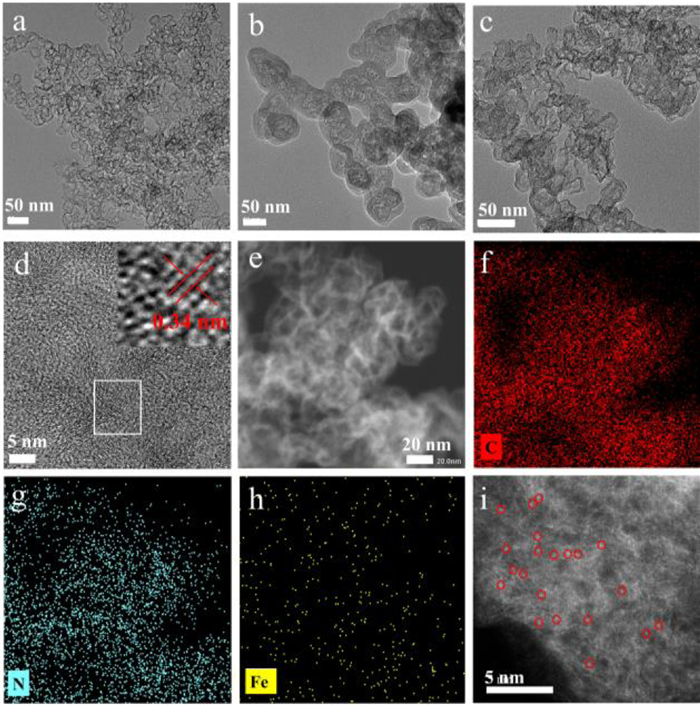
High-resolution TEM was carried out to further investigate the catalyst structure. As shown in the high-resolution TEM images (Fig. 1d and Fig. S3), higher temperature would cause increased graphitic degree of the carbonized samples. It should be noted that no Fe nanoparticles were found in whole TEM and HRTEM observation. However, both the inductively coupled plasma atomic emission spectroscopy (ICP-AES, Table S2 in Supporting information) and elemental mapping images (Figs. 1e-h) confirmed the presence of Fe, revealing that Fe existed as atomically dispersed Fe-Nx moiety. To directly observe the Fe species, sub-angstrom resolution aberration-corrected HAADF-STEM was employed. Several single bright dots (red circle in Fig. 1i) can be clearly distinguished from the nitrogen doped carbon matrix, which are attributable to isolate Fe atoms according to their Z-contrast.
The prepared carbon nanosphere composite was further studied by X-ray diffraction (XRD) and Raman spectroscopy. A broad peak at around 25o was clearly discerned in the XRD patterns for Fe-Nx-C@-900, Nx-C@C-900 and pristine C (Fig. 2a), corresponding to the (002) plane of graphitic carbon. Besides, this peak was stronger and narrower in the case of Fe-Nx-C@-900 than the Nx-C@C-900, due to the fact that Fe could catalyze the formation of graphitic carbon [24]. There were no characteristic peaks assigned to Fe-based crystallites, in line with the TEM observation, verifying the non-crystallographic characteristics of atomically dispersed Fe-Nx species. In Raman spectra, the typical carbon peaks were located at 1320 and 1590 cm−1, attributable to the D and G bands, respectively (Fig. 2b). The ratio of integrated intensities between the D band and G band (ID/IG) values were calculated to compare the graphitic degree of the materials. As shown in Fig. 2c, the ID/IG values increase in the order of Fe-Nx-C@C-900 < Nx-C@C-900 < C, indicating the highest graphitic degree of Fe-Nx-C@C-900 sample. The high graphitic degree would lead to good electronic conductivity, which is beneficial for the electron transfer in the electrochemical process.
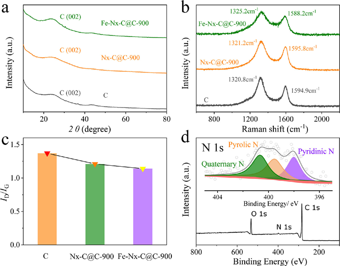
To probe the surface composition and chemical state of the catalysts, X-ray photoelectron spectroscopy (XPS) was carried out. No obvious Fe signal could be detected. This may due to the lower content of Fe species on the surface than the detection limit. The successful doping N into the Fe-Nx-C@C-900 was verified by the presence of N 1s peak in the XPS survey spectrum (Fig. 2d). The high-resolution N 1s spectra of the Fe-Nx-C@C-T can be deconvoluted into three peaks corresponding to pyridinic N (398.1 eV), pyrrolic N (399.5 eV), and quaternary N (400.7 eV) species, respectively (Fig. S7 in Supporting information). By contrast, only pyridinic N and graphitic N species were detected in the spectrum of Nx-C@C-900. The pyridinic N and pyrrolic N were believed to participate in the Fe-Nx active site formation [25], the presence of pyrrolic N in the Fe-Nx-C@C-T might imply the existence of Fe-Nx site. Notably, the N contents decreased with increasing the pyrolysis temperature, in accordance with the change of Fe content (Table S2). Higher pyrolysis temperature exacerbated N loss and Fe agglomeration, resulting in more Fe nanoparticles. These unstable Fe nanoparticles would be removed in the subsequent acid washing, thus leading to the decreased Fe content in the final catalyst [26]. There must be a strong dependence of the catalytic performance on the pyrolysis temperature, which we will discuss later.
The ORR activity for the as-synthesized catalysts was then evaluated by rotating disk electrode (RDE) and rotating ring disk electrode (RRDE) methods in O2-saturated 0.1 mol/L KOH solution. Polarization curves were obtained by linear sweeping from 1.1 V to 0 V at a scan rate of 5 mV/s at 1600 rpm (Fig. 3a). Clearly, pure carbon nanospheres exhibited considerable ORR activity with onset potential and half-wave potential of 0.81 and 0.66 V, respectively. Nitrogen doping can significantly enhance the ORR activity as the onset potential and half-wave potential on the Nx-C@C-900 sample positively shifted to 0.93 and 0.75 V, respectively. Impressively, the incorporation of Fe further promoted the ORR activity, suggesting the dominated role of Fe-Nx site. Besides, a strong dependence of pyrolysis temperature on the ORR activity was found for the various Fe-Nx-C@C-T samples, with a sequence of Fe-Nx-C@C-700 < Fe-Nx-C@C-800 < Fe-Nx-C@C-1000 < Fe-Nx-C@C-900 (Fig. S8 in Supporting information). This is because increasing the temperature resulted in higher surface area and graphitic degree, which were favorable for the active site exposure and electron transfer. On the other hand, higher temperature led to decreased active site number. Therefore, there must be a trade-off between the positive and negative effects from the temperature. It was Fe-Nx-C@C-900 that balanced these effects well and thus displaying the highest catalytic activity with onset and half-wave potential of 1.02 and 0.87 V, respectively. Noteworthy, the activity was even better than the other non-precious metal catalysts reported in literature (Table S3 in Supporting information) and commercial Pt/C catalyst, revealing its excellent activity and huge promise to replace Pt/C.
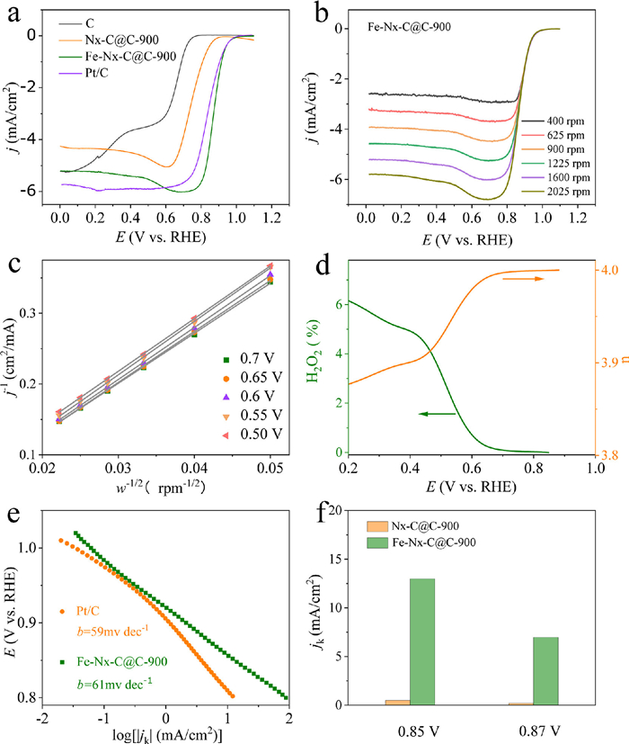
The Koutecky−Levich (K-L) plots at various electrode potentials exhibited good linearity with almost the same slope, suggesting consistent electron transfer number for ORR at different electrode potentials. The electron-transfer number (n) for ORR over Fe-Nx-C@C-900 was calculated to be ~4.0 (Figs. 3b and c), indicating a four-electron process dominating the reaction. Similar results were achieved on the other Fe-Nx-C@C-T catalysts (Fig. S9a-f in Supporting information). While for the metal-free Nx-C@C-900 counterpart, the value of n turned out to be ~3.2 (Figs. S9g and h in Supporting information). This phenomenon revealed that Fe-Nx site was superior in the ORR selectivity to the Nx-C site. The high ORR selectivity was further verified by the RRDE measurement, where the H2O2 yield is found at < 6.2% within the whole potential range (Fig. 3d). The ORR mechanism and kinetics were investigated by the Tafel curves. As depicted in Fig. 3e, Fe-Nx-C@C-900 exhibited a similar Tafel slope (61 mV/dec) as the commercial Pt/C catalyst (59 mV/dec). The similar Tafel slope suggested that they follow the same ORR pathway with the first electron transfer as rate-determining step. In sharp contrast, Nx-C@C-900 showed larger Tafel slope of 97 mV/dec (Fig. S10 in Supporting information), due to the slower ORR kinetics on the metal free Nx-C@C-900 catalyst. Quantitative analysis was obtained by comparing the kinetic current densities at fixed potentials (Fig. 3f). Specifically, at 0.85 V, the Fe-Nx-C@C-900 delivered a kinetic activity of 12.98 mA/cm2, greatly surpassing that of Nx-C@C-900 (0.4 mA/cm2).
As the stability is also an important index to evaluate a catalyst. The stability of the catalyst was estimated using an accelerated durability test (ADT) by potential cycling within a range of 0.6-1.2 V in O2-saturated 0.1 mol/L KOH solution. After 20,000 cycles, the half-wave potential of Fe-Nx-C@C-900 had negatively shifted by 11 mV (Fig. S11 in Supporting information), demonstrating its superb stability. The high long-term stability of Fe-Nx-C@C-900 catalysts can be ascribed to its high selectivity for the four-electron reduction of O2 (low H2O2 yield), stable structure of well-developed graphitic Fe-Nx-C layers and strong interaction between the carbonized Fe-Nx-C layer and the carbon support.
In summary, we developed a polymer-chelation strategy to prepare Fe-Nx-C catalyst with enriched Fe-Nx surface active sites towards ORR, where N-rich monomer was in-situ polymerized onto the commercial carbon support and then chelated with iron salts for the subsequent pyrolysis. Due to the structural merits, i.e., highly porous surface, accessible active sites, excellent conductivity, the as-obtained catalyst exhibited outstanding activity and stability toward the ORR in alkaline solutions. Especially, the optimal catalyst annealed at 900 ℃, denoted as Fe-Nx-C@C-900, displayed superior ORR activity to the Pt/C benchmark in terms of higher onset and half-wave potential. This work not only provides a highly competitive Pt-free catalyst, but also opens up an avenue to the synthesis of atomically dispersed metal site catalysts.
The authors declare that they have no known competing financial interests or personal relationships that could have appeared to influence the work reported in this paper.
The work was supported by the National Key R & D Program of China (No. 2021YFB4001200).
Supplementary material associated with this article can be found, in the online version, at doi:
R. Jasinski, Nature 201 (1964) 1212–1213. doi: 10.1038/2011212a0
K.J. Chen, K. Liu, P.D. An, et al., Nat. Commun. 11 (2020) 4173. doi: 10.1038/s41467-020-18062-y
X.Z. Yu, S.J. Lai, S.S. Xin, et al., Appl. Catal. B: Environ. 280 (2021) 119437. doi: 10.1016/j.apcatb.2020.119437
G. Wu, K.L. More, C.M. Johnston, P. Zelenay, Science 332 (2011) 443–447. doi: 10.1126/science.1200832
M.L. Xiao, H. Zhang, Y.T. Chen, et al., Nano Energy 46 (2018) 396–403. doi: 10.1016/j.nanoen.2018.02.025
Y.M. Wang, E.G. Luo, X. Wang, et al., Chin. Chem. Lett. 32 (2021) 506–510. doi: 10.1016/j.cclet.2020.03.061
G.Y. Ye, S.Q. Liu, K. Huang, et al., Adv. Funct. Mater. (2022) 2111396.
J. Wang, Z.X. Wu, L.L. Han, et al., Chin. Chem. Lett. 27 (2016) 597–601. doi: 10.1016/j.cclet.2016.03.011
H.J. Zhang, J. Geng, C.L. Cai, et al., Chin. Chem. Lett. 32 (2021) 745–749. doi: 10.1016/j.cclet.2020.05.002
J.X. Liu, C. Zhang, B.B. Xu, et al., Chem. Eng. J. 428 (2022) 131326. doi: 10.1016/j.cej.2021.131326
Y. Liang, Y. Li, H. Wang, et al., Nat. Mater. 10 (2011) 780–786. doi: 10.1038/nmat3087
Y.J. Si, Z.P. Xiong, C.G. Chen, P. Liu, H.J. Wu, Chin. Chem. Lett. 24 (2013) 1109–1111. doi: 10.1016/j.cclet.2013.09.002
S.L. Gojkovic, S. Gupta, R.F. Savinell, J. Electroanal. Chem. 462 (1999) 63–72. doi: 10.1016/S0022-0728(98)00390-8
J. Fournier, G. Lalande, R. Cote, D. Guay, J.P. Dodelet, J. Electrochem. Soc. 144 (1997) 218–226. doi: 10.1149/1.1837388
A. Zitolo, V. Goellner, V. Armel, et al., Nat. Mater. 14 (2015) 937–942. doi: 10.1038/nmat4367
H.T. Chung, D.A. Cullen, D. Higgins, et al., Science 357 (2017) 479–483. doi: 10.1126/science.aan2255
H.X. Xu, D.J. Cheng, D.P. Cao, X.C. Zeng, Nat. Catal. 1 (2018) 339–348. doi: 10.1038/s41929-018-0063-z
M. Lefèvre, E. Proietti, F. Jaouen, J. Dodelet, Science 324 (2009) 71–74. doi: 10.1126/science.1170051
Y.H. He, S. Hwang, D. Cullen, et al., Energy Environ. Sci. 12 (2019) 250–260. doi: 10.1039/C8EE02694G
M.L. Xiao, J.B. Zhu, L. Ma, et al., ACS Catal. 8 (2018) 2824–2832. doi: 10.1021/acscatal.8b00138
L.Q. Gao, M.L. Xiao, Z. Jin, et al., J. Energy Chem. 35 (2019) 17–23. doi: 10.1016/j.jechem.2018.09.019
E.G. Luo, C. Wang, Y. Li, et al., Nano Res. 13 (2020) 2420–2426. doi: 10.1007/s12274-020-2868-8
Z.H. Xing, M.L. Xiao, Z.L. Guo, W.S. Yang, Chem. Commun. 54 (2018) 4017–4020. doi: 10.1039/C8CC00846A
Y.S. Xu, L.P. Zhu, X.X. Cui, et al., Nano Res. 13 (2020) 752–758. doi: 10.1007/s12274-020-2689-9
J.K. Li, M.T. Sougrati, A. Zitolo, et al., Nat. Catal. 4 (2021) 10–19.
Z.L. Wang, X.X. Ke, K.L. Zhou, et al., J. Mater. Chem. A 9 (2021) 18515–18525. doi: 10.1039/D1TA03036A

Figure 1 TEM images of (a) pristine C, (b) PDAN@C and (c) Fe-Nx-C@C-900. (d) High-resolution TEM image for Fe-Nx-C@C-900, inset is the magnified image of the region marked in red. (e) HAADF-STEM image of Fe-Nx-C@C-900, as well as corresponding EDS mapping images of (f) C, (g) N, (h) Fe. (i) Aberration-corrected HAADF-STEM image of Fe-Nx-C@C-900.

Figure 2 (a) XRD patterns, (b) Raman spectra and (c) ID/IG comparison of pristine C, Nx-C@C-900 and Fe-Nx-C@C-900; (d) XPS survey spectrum of Fe-Nx-C@C-900, inset is the high-resolution N 1s spectra.

Figure 3 (a) ORR polarization curves of the C, Nx-C@C-900, Fe-Nx-C@C-900 and the commercial Pt/C. (b) ORR polarization curves of Fe-Nx-C@C-900 at different rotating speeds and (c) the corresponding K-L plots. (d) H2O2 yield and the calculated electron transfer number of Fe-Nx-C@C-900 based on RRDE method. (e) Tafel slopes for ORR on Fe-Nx-C@C-900 and the commercial Pt/C. (f) Comparations of kinetic current densities (Jk) between Nx-C@C-900 and Fe-Nx-C@C-900.

 扫一扫看文章

扫一扫关注我们
 DownLoad:

 下载:
下载: