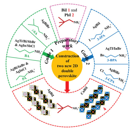
Scheme 1.
The start of design strategy of 3 and 4 according to preparatory work (1 and 2) and previous researches.
Construction, photoelectric response and phase transition for new hybrid double perovskites showing narrow band gaps
Changyuan Su , Zhixu Zhang , Jie Yao , Ming Chen , Peizhi Huang , Yi Zhang , Dawei Fu , Liyan Xie

The research about lead halide hybrid perovskite with CH3NH3PbI3 as the emblematic material have been vigorous, resulting from the unexceptionable electronic and optical properties, which endow lead halide perovskite many fascinating application directions including solar cells [1, 2], lasers [3], detectors [4, 5], ferroelectrics [6, 7], light emitting diodes [8, 9] and so on [10-14]. However, at the mention of the toxicity of lead, people become jittery, not only a long degradation lifetime in the ecological system, but also lead can do harm to nervous system and genital system, leading to a series of serious consequences [2, 15]. Therefore, the lead-free exploration and research has naturally been put on the hot spot.
In order to address the scientific challenges mentioned above, researchers attempted to do lead substitution. In the first place, chemists proposed to replace lead with same valent metals, namely, other metals admitting oxidation +2 [16], especially the environment friendly alternatives with similar inactive outer shell s-orbitals. After making unremitting endeavor, Sn2+ and Ge2+-based perovskites were born [2, 17-19], but they are being thrown into doubt due to chemical instability. In order to achieve lead-free and improve the stability of Sn2+ and Ge2+, hybrid double perovskites (HDPs) [2, 20-26], as an efficient strategy by heterovalent substitution, A2BIBⅢX6 (2BⅡ = BI + BⅢ, two metallic cations that can balance the charge to replace lead) leaped to the eyes, where BI is cation+ including group IA elements, group IB elements and group ⅢA elements, and BⅢ is cation3+ covering the vast majority of subgroup elements and sectional main group elements, in contrast, X includes VIIA elements, CN− and NO3− so far [16, 20, 27, 28], cations at A-site has unlimited possibilities by molecular design in theory. Taking a broad view, a variety of combinations give it another advantage besides low toxicity, that is, diversity, compared with divalent metal ions (Sn2+, Ge2+) [16, 20].
The diversity of HDPs can release enormous potential. Recently, Luo et al. successfully developed two HDPs based on Ag and Bi that present unique chiral polar photovoltaic, and resulting self-powered circularly polarized light detection without an external power source [29]. We also noticed that HDPs based on Ag and Bi can be used in X-ray detection with large mobility-lifetime product, and information storages as ferroelectrics [30-32]. Moreover, by applying pressure, (BA)4AgBiBr8 shows broad photoluminescence, resulting from stronger phonon coupling and stable self-trapped excitons [33]. In addition to series Ag and Bi, recently, researchers reported a series of double perovskites based on Cu and Bi, as a class of materials with a narrower band gap, they possess the temperature-dependent electrical conductivities and obvious light response behavior [34, 35].
However, up to now, 2D layered HDPs (A4BIBⅢX8) are still extremely rare, especially in series AgBiI and CuBiI with narrow band gaps and excellent carrier transport properties [34-37], resulting from appearance of more stable multiple phases caused by improper templates and the formation energy deficit brought by size mismatching. So looking up and summarizing predecessors' researches are very necessary and significant. In Scheme 1, we compared three ammonium cations including PA (propan-1-aminium) [38], BA (butan-1-aminium) [33, 39] and i-SA (3-methylbutan-1-aminium) [40], whose flexibility is the key to inserting double perovskite frameworks, just like flexible AE2T [41], but this also limits the connective octahedrons that cannot be too large to ensure the matching of the structure, otherwise there will be multiple phases. As another reported solution to construct a new 2D HDPs, researches embarked on introduction of halogen in cations including 3-CPA (3-chloropropan-1-aminium) [42], 3-BPA (3-bromopropan-1-aminium) [39] and 3-IPA (3-iodopropan-1-aminium) [37], with the change of halogens, Br-based octahedrons cannot tolerate the entry of larger ammonium ions, and finally I-based octahedrons can be used to complete the construction of the structure.
According to the above analyses and discussions, we conclude that ammonium ions with shorter chain and stronger structural rigidity and larger inorganic skeleton should be used. Firstly, solid-to-solid phase transition materials (2,2-DPA)3Bi2I9 1 and (2,2-DPA)3Pb2I7 2 were constructed. Subsequently, along the path of lead-free and two-dimensional maintenance based on 2, we successfully synthesized (2,2-DPA)4AgBiI8·H2O 3 (Fig. S1a in Supporting information) and (2,2-DPA)4CuBiI8·H2O 4 (Fig. S1b in Supporting information), whose optical band gaps are 1.98 (direct) and 1.76 eV (indirect), respectively. As the typical semiconductor, 3 and 4 show temperature-dependent conductivity, and obvious light-response when xenon lamp is on or off. Besides, we found out that dehydrated 3 is first solid-to-solid phase transition material with <100> -oriented layered double perovskites with n = 1. The cause of the phase change may be split or overturn of ammonium ions, resulting from lower motion barrier. These results mentioned above illustrate the potential application value of 3 and 4 in photoelectricity and sensors and discovery of 3 and 4 will help promote the development of layered hybrid double perovskite.
Adopting single crystal X-ray diffraction at different temperatures, the crystal structures of 1, 2, 3 and 4 were determined and their structure refinements are listed in Tables S1 and S2 (Supporting information). Measured and simulated powder X-ray diffraction patterns of 1, 2, 3 and 4 are shown in Fig. S2 (Supporting information). Like most BiI based organic-inorganic hybrid materials, the inorganic octahedrons in 1 adopt the face sharing connection mode to form a zero-dimensional structure (Fig. 1a). Different from 1, the octahedrons consisting of Pb and I in 2 are connected by face sharing and corner sharing mode, and finally a two-dimensional structure is constructed (Fig. 1b). As expected, 3 and 4 were successfully constructed by replacing Pb with Ag & Bi or Cu & Bi, employing a style of two-dimensional corner sharing sandwich structure containing double-deck filling (Figs. 1c and d) and classified as <100> -oriented layered Ruddlesden−Popper double perovskites with n = 1. In order to understand and grasp these four structures and their relationship, the Figs. 1e-g were drawn. The two corner connection points on some shared surfaces in 1 are broken, and then the octahedrons are turned, connected and tiled to finally form a two-dimensional structure of 2. Based on 2, the corner sharing two-dimensional structure of 3 and 4 is finally formed by completely breaking the two corner connection points on the shared surface.
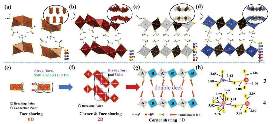
In addition, the bond lengths of 3 and 4 are shown in Fig. 1h, and the bond length and bond angle information of 1, 2, 3 and 4 are placed in Tables S3-S6 (Supporting information), distortion degree of 3 and 4 can be quantitatively estimated according to perovskite octahedra by the following equations about Δd and σθ(oct)2.
|
|
(1) |
|
|
(2) |
In the equation, Δd andσθ(oct)2 express the degree of deviation of the bond length and the bond angle variance respectively [43, 44], d is the Ag-I or Bi-I bond length and 〈d〉is the average bond, length of six M-I (M = Ag, Cu or Bi). Analogously, θ1 refers the individual I-M-I angle by comparing with 90˚ in the standard non-distorted octahedron. The calculated results of 3, 4 and other similar double perovskites are listed in the Tables S7 and S8 (Supporting information). One can see that AgI6 octahedron of 3 is disordered due to larger difference in the individual Ag-I bond length. However, on account of the existence of 2-fold rotation axes C2 in AgI6, the degree of distortion is between ones of reported AgBiI-based double perovskite. Differently, the extremely close bond lengths and 2-fold rotation axes C2 of BiI6 in 3 make its Δd the smallest. As another evaluation parameter,σθ(oct)2 parameters of AgI6 and BiI6 in 3 are smaller contrasting with ones of most following materials, whether Δd orσθ(oct)2, an analogous situation also occurs in BiI6 of 4. But in CuI6 of 4, Δd orσθ(oct)2 is the smallest. By means of simple analyses about 3 and 4, it is not difficult to find that smaller 2,2-dimethylpropan-1-aminiums cause the inorganic skeletons to deform to a small extent compared to other lager cations in addition to flexible AE2T molecules, in other words, AgBiI and CuBiI-based inorganic skeletons can give toleration to smaller cations and have an appropriate range of tolerance flexibility to different cations. Furthermore, hydrogen-bond geometries of 1, 2, 3 and 4 are listed in Tables S9-S12 and Fig. S3 (Supporting information).
As organic-inorganic hybrid materials, due to the large space between inorganic substances, it can provide the possibility of order-disorder transition of organic part at the high temperature, in other words, this provides the possibility of solid-to-solid phase transition [45, 46]. We attempted to research their thermodynamic properties by means of heating and cooling, differential scanning calorimetry (DSC) of 1, 2, 3 and 4 was performed (Figs. 2a and b). As inferred, both 1 and 2 exhibit solid-to-solid phase transition behavior. During the heating of the first lap in 3 (Fig. S4 in Supporting information), a broad peak at 365–400 K should match the drastic vibration of crystal water, implying that imminent dehydration after 400 K that is in line with TGA (Fig. S5 in Supporting information), and an abnormal endothermic peak appeared at 413.2 K. During second lap (Fig. 2b), an endothermic peak at 413.2 K arose and an exothermic peak at 407.3 K that is the same as the one during the first cooling cycle is found, indicating the occurrence of the solid-to-solid phase transition. But in 4, during the second circle, there is no abnormal peak appearing besides several dehydration peaks in the heating stage.
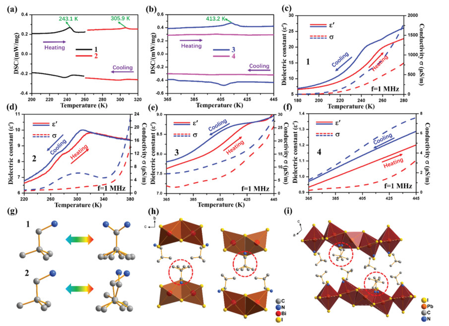
In like manner, the temperature-dependent dielectric constant ε′ was carried out and corresponding conductivity was calculated applying ε″ = ε′tanθ and σa.c. = ωε″ε0, where ε0 is permittivity of vacuum. In keeping with the results in DSC, the step-like curves dielectric constant ε′ of 1, 2 and dehydrated 3 and almost straight lines in dehydrated 4 during the heating and cooling are observed (Figs. 2c-f). By single crystal X-ray diffraction in the high temperature phase of 1 and 2, we know that the fundamental reason for the phase transition of 1 and 2 is the splitting of sectional cations in the high temperature phase, not all of them. The details are shown in Figs. 2g-i. As far as phase transition in 3 after dehydration, we attempted to carry out single crystal X-ray diffraction after phase transition temperature, but regrettably, the data quality at high temperature is extremely bad on account of the powdering of single crystal 3 resulting from dehydration, so variable-temperature powder X-ray diffraction patterns were performed to verify occurrence of phase transition. As shown in Fig. S6 in Supporting information, there are obvious changes in the peaks of three areas marked as red (2θ: 7°−13°), blue (2θ: 21°−26°), and green (2θ: 32°−36°), indicating that the phase transition occurred near 410 K. Besides, powder X-ray diffraction patterns of 3 before and after dehydration are almost the same (Fig. S7 in Supporting information), indicating that 3 still maintain initial perovskite structure after dehydration. We performed marked Hirshfeld surfaces mapped with d and the 2D fingerprint plot highlighting Hinside-Ioutside to further clarify the hydrogen bonding effect between cations and metal skeletons (Fig. S8 in Supporting information). Due to the different environment of the various ammonium ions, we have marked them to distinguish them. The specific parameters are listed in Table S13 (Supporting information), average Hinside-Ioutside surface area (29) in 3 less than that (30.2) in 4 implies that the smaller interaction in 3 reduces the motion barrier, that is, the organic cation in 3 has a greater possibility of order-disorder transition like 1 and 2, which ultimately results in the appearance of the reversible phase transition. As a solid-to-solid phase transition material that requires dehydration activation, 3 has potential application in temperature sensors and other scenarios.
For assessing the suitability for several applications such as photovoltaic applications, the UV–vis absorption and density functional theory (DFT) calculations of 1, 2, 3 and 4 were performed. 1 and 2 show the direct band gaps of 1.99 eV (Figs. S9a and c in Supporting information) and 2.32 eV (Figs. S9b and d in Supporting information), respectively. For 3 and 4, one can see that both abrupt slopes gradually appeared from ~900 nm in UV–vis absorption spectra (Figs. 3a and b) and their optical band gaps can be determined to be 1.98 and 1.76 eV respectively by Tauc plot (inset in Figs. 3a and b). In Fig. 3c, we compared 3 and 4 with the same type of series PbI and two representative double perovskites, namely <100> -oriented perovskites with n = 1. As series PbI, their optical band gaps are all located in the vicinity of 2.51 eV [47-52], the numeric fluctuation is determined by many factors such as the distortion of the PbI6 inorganic framework, ammoniums, and the interlayer spacing. Different from series PbI, due to the influence of Ag or Cu in BI and Bi in BⅢ, the optical band gaps of series AgBiI and CuBiI are around 1.99 and 1.63 eV (the average value of all reported band gaps of the same type of double perovskite, Table S14 in Supporting information) [34, 41], which are significantly lower than that of series PbI, implying that they have a greater possibility of being optoelectronic materials.
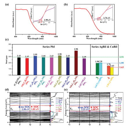
With and without spin-orbital coupling (SOC) into account, the energy band structures of 3 and 4 were obtained by calculation based on optimized structures (Figs. 3d and e, Fig. S10 in Supporting information). Without the inclusion of SOC, the valence band maximum (VBM) and conduction band minimum (CBM) of 3 are located at G point, disclosing predicted direct band gap of 2.5 eV. However, when taking the SOC into account, the predicted bandgap is direct (1.81 eV), more precise value demonstrates that necessity to include SOC for a right presentation of Pb- and Bi-based hybrid organic-inorganic perovskites [41, 53-55], the differences between SOC and no SOC are mainly derived from a split-off conduction band within Bi-6p states [41, 53]. In order to analyze composition of VBM and CBM, partial density of states of 3 in the range of −4 eV to 6 eV are shown in Fig. 3d, CBM is mainly derived from the contribution of the unoccupied Bi-p and I-p orbitals. Similarly to the role of the inorganic skeleton in CBM, VBM mainly arises from I-p states. Differently, the VBM and CBM of 4 are located at Q and G point respectively and predicted indirect band gaps are 2.21 eV (no SOC) and 1.6 eV (SOC), where CBM is mainly contributed by Bi-p and I-p orbitals and VBM mainly arises from Cu-d and I-p states (Fig. 3e). Unlike the differences in 3, the differences between SOC and no SOC in 4 are derived from a split-off in conduction band of Bi-6p states and valence band of Cu-3d states. Whether in 3 or 4, for organic part, a wide range of overlap of H-s, N-p, C-p and O-p states indicates a strong interaction between them, especially the strong covalent interactions between H-s, N-p and C-p orbitals.
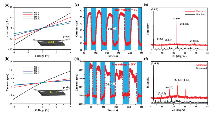
To further illustrate the semiconductor properties of 3 and 4, the voltage-dependent current of 3 (Fig. 4a) on the plane (200) and 4 (Fig. 4b) on the plane (011) at various temperatures were performed, where the crystal plane (200) and (011) are two-dimensional planes of 3 and 4, respectively. As the temperature increasing with every 10 K, under the same voltage, current of 3 and 4 increase by a greater magnitude, making clear that representative semiconducting nature. Furthermore, photoconductivity of 3 and 4 were also tested on the plane (200) and the plane (011). Both crystal 3 and 4 show obvious photo-response (Figs. 4c and d) when the xenon lamp with intensity of 20 mW/cm2 is on or off, which further proves their semiconductor properties and indicates that they may be applied to light-harvesting and light-detecting devices. Furthermore, we attempted to research their photo-response between parallel two-dimensional crystal planes, namely (200)/(200) of 3 and (011)/(011) of 4, however, the photo-response is not found, resulting from the gaps between the two-dimensional planes leading to poor conductivity and insufficient light intensity, possibly. The detailed test diagrams are shown in Fig. S11 (Supporting information). In addition, Figs. 4e and f show PXRD of 3 and 4 used to determine the crystal plane in the I-V and I-t-test, respectively.
In conclusion, by preparatory work in 1 and 2, and applying the new scheme using the adjustment of cations and inorganic octahedrons, two 2D hybrid double perovskites, (2,2-DPA)4AgBiI8·H2O 3 and (2,2-DPA)4CuBiI8·H2O 4 were successfully synthesized, which show the optical band gap of 1.98 and 1.76 eV respectively. As the representative semiconductors, they exhibit obvious photo-response when the xenon lamp with intensity of 20 mW/cm2 is on or off. Besides, (2,2-DPA)4AgBiI8·H2O was proven to be the first solid-to-solid phase transition material with <100> -oriented layered double perovskites with n = 1 after dehydration. We believed that the discovery of 3 and 4 is extremely significative, whether it is the development of layered hybrid double perovskites or its potential to photo-response devices and temperature sensors.
The authors declare that they have no known competing financial interests or personal relationships that could have appeared to influence the work reported in this paper.
This work was financially supported by the National Natural Science Foundation of China (No. 21991141).
The supplementary crystallographic data for this paper have been uploaded in the Cambridge Structural Database. The number of CCDC are as follows: 2115529 (1 at 200 K), 2115530 (1 at 300 K), 2115531 (2 at 223 K), 2115532 (2 at 310 K), 2092452 (3 at 130 K) and 2092453 (4 at 150 K).
Supplementary material associated with this article can be found, in the online version, at doi:
X.L. Xu, L.B. Xiao, J. Zhao, et al., Angew. Chem. Int. Ed. 59 (2020) 19974–19982. doi: 10.1002/anie.202008494
Q. Zhang, F. Hao, J. Li, et al., Sci. Technol. Adv. Mater. 19 (2018) 425–442. doi: 10.1080/14686996.2018.1460176
S. Wang, J. Fang, C. Zhang, et al., Adv. Opt. Mater. 5 (2017) 1700529. doi: 10.1002/adom.201700529
V. Adinolfi, W. Peng, G. Walters, et al., Adv. Mater. 30 (2018) 1700764. doi: 10.1002/adma.201700764
W. Xu, M. Niu, X. Yang, et al., Chin. Chem. Lett. 32 (2021) 489–492. doi: 10.1016/j.cclet.2020.05.017
H.Y. Zhang, Z.X. Zhang, X.G. Chen, et al., J. Am. Chem. Soc. 143 (2021) 1664–1672. doi: 10.1021/jacs.0c12907
X.G. Chen, X.J. Song, Z.X. Zhang, et al., J. Am. Chem. Soc. 142 (2020) 10212–10218. doi: 10.1021/jacs.0c03710
H. Yu, H. Wang, G. Pozina, et al., Chem. Sci. 11 (2020) 11338–11343. doi: 10.1039/d0sc04508j
X.Y. Chin, D. Cortecchia, J. Yin, et al., Nat. Commun. 6 (2015) 7383. doi: 10.1038/ncomms8383
S. Yang, W. Niu, A.L. Wang, et al., Angew. Chem. Int. Ed. 56 (2017) 4252–4255. doi: 10.1002/anie.201701134
S. Liu, L. He, Y. Wang, et al., Chin. Chem. Lett. 33 (2022) 1032–1036. doi: 10.1016/j.cclet.2021.07.039
Z.X. Zhang, H.Y. Zhang, W. Zhang, et al., J. Am. Chem. Soc. 142 (2020) 17787–17794. doi: 10.1021/jacs.0c09288
C. Zhang, T. Li, L. Pu, et al., Chin. Chem. Lett. 31 (2020) 2499–2502. doi: 10.1016/j.cclet.2020.01.013
C. Su, M. Lun, Y. Chen, et al., CCS Chem. 3 (2021) 2021–2031.
A. Babayigit, A. Ethirajan, M. Muller, et al., Nat. Mater. 15 (2016) 247–251. doi: 10.1038/nmat4572
B. Vargas, G. Rodriguez-Lopez, D. Solis-Ibarra, ACS Energy Lett. 5 (2020) 3591–3608. doi: 10.1021/acsenergylett.0c01867
H.Y. Zhang, X.G. Chen, Z.X. Zhang, et al., Adv. Mater. 32 (2020) 2005213. doi: 10.1002/adma.202005213
G.P. Li, S.Q. Lu, X. Chen, et al., Chem. Eur. J. 25 (2019) 16625–16629. doi: 10.1002/chem.201903678
X. Wang, T. Zhang, Y. Lou, et al., Mater. Chem. Front. 3 (2019) 365–375. doi: 10.1039/c8qm00611c
N.R. Wolf, B.A. Connor, A.H. Slavney, et al., Angew. Chem. Int. Ed. 60 (2021) 16264–16278. doi: 10.1002/anie.202016185
B.A. Connor, R.W. Smaha, J. Li, et al., Chem. Sci. 12 (2021) 8689–8697. doi: 10.1039/d1sc01159f
Q.R. Meng, W.J. Xu, W.H. Hu, et al., Chem. Commun. 57 (2021) 6292–6295. doi: 10.1039/d1cc02085d
F. Schmitz, J. Horn, N. Dengo, et al., Chem. Mater. 33 (2021) 4688–4700. doi: 10.1021/acs.chemmater.1c01182
D. Fu, S. Wu, Y. Liu, et al., Inorg. Chem. Front. 8 (2021) 3576–3580. doi: 10.1039/d1qi00219h
Y. Sun, W. Chen, Z. Sun, Chin. Chem. Lett. 33 (2022) 1772–1778. doi: 10.1016/j.cclet.2021.08.055
M.M. Hua, L. Ye, Q.W. Wang, et al., J. Mater. Chem. C 8 (2020) 16349–16353. doi: 10.1039/d0tc04386a
X.G. Zhao, D. Yang, J.C. Ren, et al., Joule 2 (2018) 1662–1673. doi: 10.1016/j.joule.2018.06.017
C.Y. Su, Y.F. Yao, Z.X. Zhang, et al., Chem. Sci. 13 (2022) 4794–4800. doi: 10.1039/d1sc07045b
D. Li, X. Liu, W. Wu, et al., Angew. Chem. Int. Ed. 60 (2021) 8415–8418. doi: 10.1002/anie.202013947
Z. Xu, X. Liu, Y. Li, et al., Angew. Chem. Int. Ed. 58 (2019) 15757–15761. doi: 10.1002/anie.201909815
W. Zhang, M. Hong, J. Luo, Angew. Chem. Int. Ed. 59 (2020) 9305–9308. doi: 10.1002/anie.201916254
C.F. Wang, H. Li, M.G. Li, et al., Adv. Funct. Mater. 31 (2021) 2009457. doi: 10.1002/adfm.202009457
Y. Fang, L. Zhang, L. Wu, et al., Angew. Chem. Int. Ed. 58 (2019) 15249–15253. doi: 10.1002/anie.201906311
L.Y. Bi, T.L. Hu, M.Q. Li, et al., J. Mater. Chem. A 8 (2020) 7288–7296. doi: 10.1039/d0ta00949k
L.Y. Bi, Y.Q. Hu, M.Q. Li, et al., J. Mater. Chem. A 7 (2019) 19662–19667. doi: 10.1039/c9ta04325j
M.S. Lassoued, L.Y. Bi, Z. Wu, et al., J. Mater. Chem. C 8 (2020) 5349–5354. doi: 10.1039/d0tc01017k
Y. Yao, B. Kou, Y. Peng, et al., Chem. Commun. 56 (2020) 3206–3209. doi: 10.1039/c9cc07796k
L. Mao, S.M.L. Teicher, C.C. Stoumpos, et al., J. Am. Chem. Soc. 141 (2019) 19099–19109. doi: 10.1021/jacs.9b09945
B.A. Connor, R.I. Biega, L. Leppert, et al., Chem. Sci. 11 (2020) 7708–7715. doi: 10.1039/d0sc01580f
Y. Li, T. Yang, Z. Xu, et al., Angew. Chem. Int. Ed. 59 (2020) 3429–3433. doi: 10.1002/anie.201911551
M.K. Jana, S.M. Janke, D.J. Dirkes, et al., J. Am. Chem. Soc. 141 (2019) 7955–7964. doi: 10.1021/jacs.9b02909
W. Guo, X. Liu, S. Han, et al., Angew. Chem. Int. Ed. 59 (2020) 13879–13884. doi: 10.1002/anie.202004235
K. Robinson, G.V. Gibbs, P.H. Ribbe, Science 172 (1971) 567–570. doi: 10.1126/science.172.3983.567
J.A. Alonso, M.J. Martinez-Lope, M.T. Casais, et al., Inorg. Chem. 39 (2000) 917–923. doi: 10.1021/ic990921e
D.W. Fu, J.X. Gao, W.H. He, et al., Angew. Chem. Int. Ed. 59 (2020) 17477–17481. doi: 10.1002/anie.202007660
Y. Xie, Y. Ai, Y.L. Zeng, et al., J. Am. Chem. Soc. 142 (2020) 12486–12492. doi: 10.1021/jacs.0c05372
C.C. Stoumpos, D.H. Cao, D.J. Clark, et al., Chem. Mater. 28 (2016) 2852–2867. doi: 10.1021/acs.chemmater.6b00847
T. Ishihara, J. Lumin. 60 (1994) 269–274.
O. Nazarenko, M.R. Kotyrba, M. Worle, et al., Inorg. Chem. 56 (2017) 11552–11564. doi: 10.1021/acs.inorgchem.7b01204
K. Pradeesh, G.S. Yadav, M. Singh, et al., Mater. Chem. Phys. 124 (2010) 44–47. doi: 10.1016/j.matchemphys.2010.07.037
M. Daub, H. Hillebrecht, Z. Kristallogr. Cryst. Mater. 233 (2018) 555–564. doi: 10.1515/zkri-2018-2055
M. Safdari, P.H. Svensson, M.T. Hoang, et al., J. Mater. Chem. A 4 (2016) 15638–15646. doi: 10.1039/C6TA05055G
M.R. Filip, S. Hillman, A.A. Haghighirad, et al., J. Phys. Chem. Lett. 7 (2016) 2579–2585. doi: 10.1021/acs.jpclett.6b01041
J. Even, L. Pedesseau, J.M. Jancu, et al., J. Phys. Chem. Lett. 4 (2013) 2999–3005. doi: 10.1021/jz401532q
J. Even, L. Pedesseau, M.A. Dupertuis, et al., Phys. Rev. B 86 (2012) 205301. doi: 10.1103/PhysRevB.86.205301

Scheme 1 The start of design strategy of 3 and 4 according to preparatory work (1 and 2) and previous researches.

Figure 1 Basic structures and inorganic skeleton stacking diagrams (inset) of (a) 1, (b) 2, (c) 3 and (d) 4 at low temperature phase. Diagrammatic drawing of (e) 1, (f) 2, (g) 3 and 4, the transformation relationship of their inorganic skeleton. (h) Bond lengths in inorganic parts of 3 and 4.

Figure 2 (a) DSC of 1 and 2. (b) DSC of 3 and 4 in the second lap. (c-f) Dielectric constant ε′ and conductivity σ of 1-4 as a function of temperature. (g) Changes of organic cations in 1 and 2 at low temperature phase and high temperature phase. (h, i) Packing structures of 1 and 2 at high temperature phase.

Figure 3 The UV–vis absorption spectra of (a) 3 and (b) 4, and corresponding Tauc plots. (c) Optical band gaps of <100> -oriented 2D hybrid perovskites with n = 1 based on PbI, AgBiI and CuBiI. Calculated energy band structure of (d) 3 and (e) 4 without and with spin-orbit coupling (SOC), and corresponding partial density of states (PDOS).

Figure 4 I-V curve at different temperatures on (a) the plane (200) of crystal 3 and (b) the plane (011) of crystal 4. I–t plots of the light on/off cycles at 290 K on (c) the plane (200) of crystal 3 under a bias voltage of 2 V and (d) the plane (011) of crystal 4 under a bias voltage of 20 V. PXRD of (e) 3 and (f) 4 used to determine the crystal plane in the I-V and I-t-test.

 扫一扫看文章

扫一扫关注我们
 DownLoad:
 下载:
下载: