Citation:
Xu Zhou, Chunyan Wang, Fulin Liu, Chengyu He, Shiming Zhang. Insight into the improvement mechanism of Co−Pi-modified hematite nanowire photoanodes for solar water oxidation☆[J]. Chinese Chemical Letters,
2021, 32(10): 3261-3263.
doi:
10.1016/j.cclet.2021.05.015
Insight into the improvement mechanism of Co−Pi-modified hematite nanowire photoanodes for solar water oxidation☆
English
Insight into the improvement mechanism of Co−Pi-modified hematite nanowire photoanodes for solar water oxidation☆
Received Date:
26 August 2020 Accepted Date:
14 May 2021 Revised Date:
10 February 2021 Available Online:
01 October 2021
Abstract:
The composite photoanodes composed by cobalt phosphate catalyst (Co−Pi) modified semiconductor have been widely used for solar water splitting, but the improvement mechanism has not been experimentally confirmed. Here we use transient photoelectrochemical measurements and impedance spectroscopy to investigate the effect of Co−Pi catalyst on hematite nanowire photoanode. It is found that under illumination the Co−Pi catalyst can efficiently promote the transfer of photo-generated holes to the Co−Pi layer by increasing the electrical conductivity of the composite structure under a low potential. The Co−Pi catalyst can recombine with photo-generated electrons to reduce the surface recombination efficiency of photo-generated holes and electrons under a high potential. These results provide important new understanding of the performance improvement mechanism for the Co−Pi-modified semiconductor nanowire composite photoanodes.
Photoelectrochemical splitting of water into hydrogen and oxygen using solar energy could provide a renewable energy cycle to address the global energy problem [1-3]. Artificial solar water-splitting devices are now being designed and tested by using inorganic materials composed of light-harvesting semiconductors and gas-evolving catalysts [4, 5]. Hematite (α-Fe2O3) is currently a leading photoanode in photoelectrochemical configurations due to its appropriate bandgap and valence-band energy, low cost, and chemical stability [6-12]. However, hematite has low minority charge carrier mobility, short lifetimes and a large applied potential needed to produce a photocurrent, which limits its photoelectrocatalytic application [13-15]. Recent studies have shown that modification of hematite by co-catalyst, such as IrO2 nanoparticles, cobalt ions, and the cobalt phosphate catalyst (Co−Pi), can effectively increase its photoelectrocatalytic water oxidation properties [16-22]. Typically, Co−Pi-modified hematite has attracted exceptional attention because Co−Pi is an effective water oxidation electrocatalyst operating at moderate overpotentials [19-23]. These Fe2O3/Co−Pi composite photoanodes show cathodic shifts of 100–200 mV in their photocurrent onset potentials. So the improvement mechanism of Co−Pi-modified hematite photoanodes for solar water oxidation has aroused great interest of scientists [24-29]. Barroso, Durrant and colleagues used transient absorption spectroscopy to study the Fe2O3/Co−Pi composite photoanodes for solar water oxidation. They demonstrated that the function of Co−Pi was not a catalyst but a retardation of electron/hole recombination by trapping electrons of Fe2O3 [24]. Hamann et al. employed impedance and transient photocurrent spectroscopies to probe the influence of Co−Pi on the photoelectrocatalytic performance of planar Fe2O3 photoanodes. The results showed that the role of Co−Pi was to rapidly extract photo-generated holes from Fe2O3 and catalyze water oxidation [25]. These studies expose the fact that there is still no solid evidence that Co−Pi actually participates in the water-oxidation reactions in this system. Therefore, further research into this and related composite photoanodes is still needed and can be anticipated ultimately to advance the development of efficient solar water-splitting devices for the production of H2 and other chemical fuels.
In this study, we use transient photoelectrochemical measurements and impedance spectroscopy to investigate the effect of the Co−Pi catalyst on hematite nanowire photoanodes. It is found that the role of Co−Pi is dependent on applied potentials. At low potentials, Co−Pi promotes the transfer of photo-generated holes to the Co−Pi layer by increasing the electrical conductivity of the composite structure and catalyzes the water oxidation reaction. At high potentials, Co−Pi can recombine with photo-generated electrons, thereby reducing the surface recombination efficiency of photo-generated holes and electrons, allowing holes to migrate to the surface of hematite nanowires to participate in the water oxidation reaction. The insight into the mechanism can provide guidance for the design of high-performance photoelectrodes.
Iron oxide nanowires were directly grown from and on the corresponding iron substrate by thermal oxidation at ultra-low pressure [30]. The reaction system was heated to the designed temperature (550 ℃), and then O2–Ar (O2, 40 vol%) mixture with a flow rate of 12 sccm was introduced into the tube as the reagent gas. The system was maintained in the pressure of 10 Pa by a high-power mechanical pump. After 60 min of reaction, the system was cooled down to room temperature in Ar, and a homogeneous layer was formed on the substrate. Co−Pi catalyst was deposited onto hematite nanowires by photoassisted electrodeposition [21, 25]. Hematite nanowire electrode was immersed in a solution containing 0.5 mmol/L Co(NO3)2•6H2O in a 0.5 mol/L phosphate buffer (pH 7.0). The potentials were reported as measured versus the Ag/AgCl electrode and as calculated versus the reversible hydrogen electrode (RHE) using the following formula: E(RHE) = E(Ag/AgCl) + 0.205 V + 0.059 pH. A bias of 0.90 V vs. RHE was applied under illumination. The amount of Co−Pi was controlled by varying the amount of charge allowed to pass during the deposition. The products were characterized by scanning electron microscopy (SEM; JEOL JSM-7800F) and X-ray diffraction (XRD; Rigaku SmartLab X-ray diffractometer).
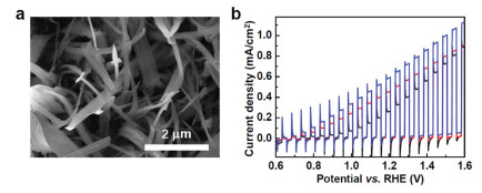
XRD tests show that no new characteristic peaks appear after deposition of Co−Pi catalysts, which shows amorphous features of the electrodeposited catalyst [23]. From the SEM image, it can be seen that the nanowires are smooth with their length about 10 μm. After deposition of Co−Pi catalyst, the surfaces of the nanowires become rough (Fig. 1a). From the above results, it can be concluded that the Fe2O3/Co−Pi nanowire composite photoanodes have been prepared. The photoelectrochemical water oxidation measurements were performed at ambient temperature in a three-electrode cell connected to a zahner electrochemical workstation (CIMPS-2). The as-prepared samples were used as the working electrode whereas Ag/AgCl (3.5 mol/L KCl-filled) and platinum wire served as the reference and auxiliary electrodes, respectively. The electrolyte was 0.1 mol/L NaOH solution (pH 12.6). The photocurrents were measured under irradiation from a lamp and the intensity was adjusted to 1 sun (100 mW/cm2) by means of a calibrated Si photodiode. To compare the properties of bare hematite nanowires and catalyst-modified hematite nanowires, linear sweep voltammetry (LSV) was performed. Fig. 1b shows LSV curves measured under 1 sun illumination of a bare Fe2O3 electrode and the Fe2O3/Co−Pi electrodes with 15 and 30 mC/cm2 Co−Pi catalysts. We can determine that the deposition of Co−Pi onto hematite nanowires improves its ability for water oxidation.
Figure 1
Figure 1.
(a) SEM image of a hematite/Co−Pi sample. The Co−Pi catalyst was deposited by passing 30 mC/cm2. (b) Current-potential curves measured for a bare hematite nanowire electrode (black line) and the Fe2O3/Co−Pi electrodes with 15 (red line) and 30 mC/cm2 (blue line) Co−Pi catalysts. The measurements were performed at 10 mV/s in 0.1 mol/L NaOH solution under chopped 1 sun illumination.
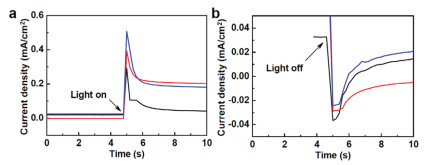
Current transients in response to turning on (anodic) and turning off (cathodic) 1 sun illumination were measured at a constant potential. Examples of anodic and cathodic current transients for hematite nanowire electrodes coated with different amount of Co−Pi measured at an applied bias of 1.10 V vs. RHE can be seen in Fig. 2. At the moment of turning on/off the light source, there will be a momentary current spike which quickly decays to a stable current density. These spikes are attributed to the oxidizing and reducing of surface species. The sudden change of the current density is attributed to the surfaces of hematite nanowires undergo a charging and discharging process, which is similar to a capacitor. The intensity of the spike and the amount of charge passing during the transient process increase with the increase of the Co−Pi deposition, which indicates that the process of this transient change is controlled by the amount of Co−Pi. The anodic transients are attributed to the oxidation of Co3+ in the Co−Pi catalyst layer to Co4+ by photo-generated holes [31-34]. Such a large amount of charge transfer means that the conversion between Co3+ and Co4+ plays a major role in the transient process, indicating that the holes in hematite nanowires have been transferred and stored in the Co−Pi layer.
Figure 2
Figure 2.
(a) Current transients measured in response to turning on (a) and turning off (b) 1 sun illumination for a bare hematite nanowire electrode (black line) and the Fe2O3/Co−Pi electrodes with 15 (red line) and 30 (blue line) mC/cm2 Co−Pi catalysts. The measurements were performed in 0.1 mol/L NaOH solution at an applied bias of 1.10 V vs. RHE.
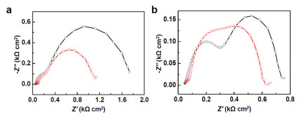
We also performed impedance spectroscopy measurements on the photoelectrodes with different Co−Pi deposition. Impedance spectroscopy data were gathered using a 10 mV amplitude perturbation with the frequency between 0.01 and 100,000 Hz. The Nyquist diagrams of a bare hematite nanowire electrode and an electrode with 30 mC/cm2 Co−Pi catalyst under 1 sun illumination at different potentials can be seen in Fig. 3. Both the bare hematite nanowire electrode and the hematite nanowire electrode coated with Co−Pi have two semicircles. In the low frequency (high impedance) region, a smaller impedance loop diameter means faster charge transfer. From Fig. 3, it can be seen that Co−Pi reduces the semicircular diameter of the impedance loop, which means that Co−Pi can promote the charge transfer of the Fe2O3/Co−Pi composite structure and improve the photoelectrocatalytic water oxidation properties. Meanwhile, it can be found that the diameter of the impedance ring begins to close to each other with the increasing of applied bias, which means that the main factor affecting the water oxidation reaction under high bias is no longer the interface charge transfer.
Figure 3
Figure 3.
Nyquist plots of a bare hematite nanowire electrode (black) and a Fe2O3/Co−Pi electrode with 30 mC/cm2 Co−Pi catalyst (red) measured in a 0.1 mol/L NaOH solution under 1 sun illumination at applied bias of 1.00 V (a) and 1.30 V (b) vs. RHE.
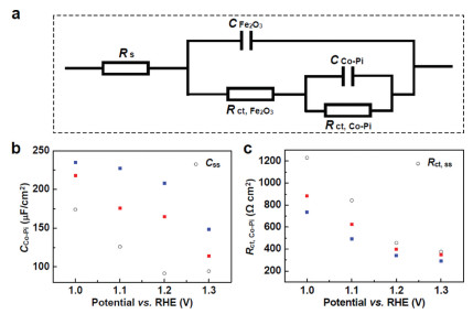
To get a deeper insight into the photoelectrochemical process, the impedance spectra of Fe2O3/Co−Pi electrodes with varying amounts of Co−Pi catalysts were fit to the equivalent circuit shown in Fig. 4a. The equivalent circuit consists of the solution resistance of the electrolyte (Rs), the capacitance (CFe) and charge transfer resistance (Rct,Fe) of the hematite nanowires, and the capacitance (CCo-Pi) and charge transfer resistance (Rct, Co-Pi) of the Co−Pi layer 25. According to the equivalent circuit, the resistance and capacitance of each component of the system can be calculated from the data of the impedance tests and the results are shown in Figs. 4b and c. Fig. 4b shows plots of CCo-Piversus applied potential for the different thicknesses of Co−Pi deposited on the hematite nanowires. The deposition of Co−Pi can increase the capacitance inside Co−Pi layer, and as the applied potential increases, the capacitance value decreases (Fig. 4b). It is thus concluded that the Co−Pi layer improves the charge transport efficiency by storing photo-generated holes. Under a low potential, the introduction of Co−Pi can effectively reduce the resistance at the interface between the semiconductor and the electrolyte (Fig. 4c). At a high potential, the charge transfer resistance at the interface is not the main factor affecting water oxidation. We speculate that the Co−Pi catalyst can recombine with photo-generated electrons to reduce the surface recombination efficiency of photo-generated holes and electrons under a high potential.
Figure 4
Figure 4.
(a) Proposed equivalent circuit used for interpretation of Co−Pi-modified hematite nanowire photoanodes. (b, c) CCo−Pi and Rct, Co−Pi values fit from impedance measurements for the Fe2O3/Co−Pi electrodes with 15 (red squares) and 30 (blue squares) mC/cm2 Co−Pi catalysts. Bare hematite nanowire electrode fitting parameters of Css and Rct, ss (black open circles) are shown for comparison. The measurements were performed in 0.1 mol/L NaOH solution under 1 sun illumination.
In conclusion, we use transient photoelectrochemical measurements and impedance spectroscopy to investigate the mechanism of Co−Pi-modified hematite nanowire photoanodes for solar water oxidation. We propose a possible mechanism for improving photoelectrocatalytic water oxidation properties of the Fe2O3/Co−Pi composite structure. First, Co−Pi promotes the transfer of photo-generated holes to the Co−Pi layer by increasing the electrical conductivity of the composite structure under a low potential. The photo-generated holes are stored in the conversion between Co(Ⅲ) and Co(Ⅳ) and catalyze the water splitting reaction. Second, the Co−Pi catalyst can recombine with photo-generated electrons to reduce the surface recombination efficiency of photo-generated holes and electrons under a high potential. Holes can migrate into the electrolyte more easily to participate in the oxygen evolution reaction. The in-depth insight provides important new understanding of the enhancement of semiconductor photoelectrodes modified by the amorphous Co−Pi electrocatalyst for solar water splitting.
Declaration of competing interest
The authors declare that they have no known competing financial interests or personal relationships that could have appeared to influence the work reported in this paper.
Acknowledgments
This work is financially supported by the National Natural Science Foundation of China (No. 21503109) and the Research-Starting Funds for Introduced Talents of Nanjing Tech University.
[1]
M.S. Dresselhaus, I.L. Thomas, Nature 414(2001) 332-337. doi: 10.1038/35104599
Figure 1
(a) SEM image of a hematite/Co−Pi sample. The Co−Pi catalyst was deposited by passing 30 mC/cm2. (b) Current-potential curves measured for a bare hematite nanowire electrode (black line) and the Fe2O3/Co−Pi electrodes with 15 (red line) and 30 mC/cm2 (blue line) Co−Pi catalysts. The measurements were performed at 10 mV/s in 0.1 mol/L NaOH solution under chopped 1 sun illumination.
Figure 2
(a) Current transients measured in response to turning on (a) and turning off (b) 1 sun illumination for a bare hematite nanowire electrode (black line) and the Fe2O3/Co−Pi electrodes with 15 (red line) and 30 (blue line) mC/cm2 Co−Pi catalysts. The measurements were performed in 0.1 mol/L NaOH solution at an applied bias of 1.10 V vs. RHE.
Figure 3
Nyquist plots of a bare hematite nanowire electrode (black) and a Fe2O3/Co−Pi electrode with 30 mC/cm2 Co−Pi catalyst (red) measured in a 0.1 mol/L NaOH solution under 1 sun illumination at applied bias of 1.00 V (a) and 1.30 V (b) vs. RHE.
Figure 4
(a) Proposed equivalent circuit used for interpretation of Co−Pi-modified hematite nanowire photoanodes. (b, c) CCo−Pi and Rct, Co−Pi values fit from impedance measurements for the Fe2O3/Co−Pi electrodes with 15 (red squares) and 30 (blue squares) mC/cm2 Co−Pi catalysts. Bare hematite nanowire electrode fitting parameters of Css and Rct, ss (black open circles) are shown for comparison. The measurements were performed in 0.1 mol/L NaOH solution under 1 sun illumination.

 DownLoad:

 下载:
下载:


