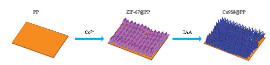
Figure 1.
The preparation process of Co9S8@PP separator.
MOF-derived Co9S8 nano-flower cluster array modified separator towards superior lithium sulfur battery
Qi Wang , Hanqing Zhao , Boya Li , Chenhui Yang , Mingyang Li , Yanan Li , Peng Han , Miaomiao Wu , Tengyu Li , Ruiping Liu

Lithium ion batteries cannot meet the rapid increasing requirements for the electric vehicles, hybrid electric vehicles and portable devices due to its relative lower energy density [1, 2]. Lithium-sulfur (Li-S) battery which can be used as the energy storage devices for electric vehicles and portable devices has been gained much more attentions because of its high theoretical capacity (1675 mAh/g) and energy density (2567 Wh/kg), environmentally friendly as well as abundant in resource [3-7]. However, the insulating properties of sulfur and discharge products Li2S, large volume expansion of sulfur during the electrochemical process, the sluggish reaction kinetics of the reduction intermediates lithium polysulfide (LiPSs) and the "shuttle effect" caused by the dissolution of LiPSs into electrolyte reduce the utilization of the active sulfur, and thus weaken the electrochemical performance of the lithium sulfur batteries [8-12].
To overcome the above challenges, numerous strategies have been proposed, including electrode structure modification [13-15], separator decoration [16, 17], interlayer insertion and electrolyte optimization [18-20]. One of the most important strategies is to construct a host material to restrain the sulfur and polysulfides [21-23]. The pioneer work has been done by Nazar group in 2009, in which the mesoporous carbon was first employed as sulfur host in cathode [24], and inspired by this, carbon materials with various structures such as multilayer, hollow and yolk-shell structure were designed, synthesized and used as efficient sulfur host [25, 26]. All of the above strategies are effective in alleviating the "shuttle effects" to some extent, yet the physical constrains and weak physical bonding between carbon materials and polysulfides caused by nonpolar characteristics of carbon materials are feeble for fastening the polysulfides at the cathode side. To enhance the adsorption ability of the polysulfides, polar materials including surface functionalized carbon, metal oxide, metal sulfides and conducting polymer have been introduced as the host materials in Li-S battery, and the strong chemical bonding between the polar materials and polysulfides can be achieved [27, 28]. However, the complicated synthesis procedures, the poor electric conductivity and the limited sulfur mass loading are the main issues toward practical application.
Modifying the separator is another most efficient strategy to alleviate the shuttle effect and accelerate the reaction kinetics of polysulfides without the sulfur loading limitation [29, 30]. Graphene and its hybrids are the most common materials used for separator modification, and the shuttle effect can be suppressed effectively [31, 32]. However, the weak physical bonding and sluggish conversion kinetics of separators modified with graphene-based materials also deteriorate the electrochemical performance of lithium sulfur battery [33]. Herein, a unique Co9S8 nanostructure derived from metal organic framework material (MOF) was in situ prepared on the surface of polypropylene by simple liquid phase reaction and a subsequent heat vulcanization (Co9S8@PP). The regulated Co9S8 with nano-flower structure and large specific surface area on the PP separator cannot only absorb the polysulfides by forming chemical bonding, but also accelerate the reaction kinetics by the catalytic effect of the Co9S8, and thus the electrochemical performance of the LSBs with modified separator were largely improved.
Fig. 1 displays the preparation process of petal shaped Co9S8 in situ grown on the surface of PP separator through liquid phase reaction. Firstly, Co2+ combines with C4H6N2+ forming evenly arranged Co based MOF on the surface of PP after the Co(NO3)2 dissolved in 2-methylimidazole solution. Then the as-prepared MOF@PP is introduced into TAA aqueous solution, the electropositive acetamido from TAA absorbs on the surface of MOF. During hydrothermal treatment, the Co9S8 will be obtained through the sulfurization reaction, and at the same time, the MOF will be partially decomposed to porous carbon materials.
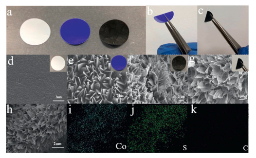
Fig. 2 shows the morphologies of MOF@PP and Co9S8@PP. After grown MOF on the surface of PP, the color of the separator changes from white to dark blue, and finally turns to black after the formation of Co9S8 (Fig. 2a). The strong adhesion between the Co9S8 and PP can be demonstrated through the bending test (Figs. 2b and c). As shown in Fig. 2d, the smooth surface of PP can be clearly observed, and after MOF modification, the products possess high porosity and unified petal shaped structure with the size of around 200 nm on one side of PP, and after sulfureting, the surface of petals become pretty rougher (Figs. 2e-g). The closely packed nano-flaky Co9S8 on the surface of PP separator would benefit for adsorbing polysulfide. The elemental mapping of Co9S8@PP has been detected by EDX, and the homogenously distributed of Co and S can be observed on the nano petal, demonstrating the successful preparation of nano Co9S8 on the surface of commercial PP separator. The carbon may be ascribed to the decomposition of the MOF after hydrothermal treatment (Figs. 2h-k).
The XRD patterns (Fig. S1 in Supporting information) exhibit the crystal structure of MOF@PP and Co9S8@PP. The XRD peaks located at 7.36°, 10.42°, 12.78° and 18.1° are coincident well with the crystal face of (011), (002), (112) and (222) of ZIF-67, suggesting that the MOF has been in-situ grown on the PP separator by liquid phase reaction [34]. After sulfidation MOF@PP in TAA, the XRD peaks located at 18.04° and 38.37° are corresponded to the crystal face of (400) and (800) of Co9S8, and it can be obtained from the Scherrer equation that the crystallite size of Co9S8 is about 10 nm, indicating that the Co9S8 was successfully synthesized on the surface of PP separator.
The specific surface area and pore size distribution of Co9S8 synthesized were measured based on BET nitrogen absorption desorption experiment. As shown in Fig. S2 (Supporting information), N2 adsorption-desorption isotherm slightly raises from start at the low-pressure region, and forms closed loop at the high-pressure region, which can be classified to be a H3 hysteresis loop of typical type-Ⅳ curve according to Langmuir adsorption model, indicating the as-obtained Co9S8 possesses abundant mesopores. The specific surface area and pore volume are 109.750 m2/g and 0.108 cc/g, respectively. The mean pore size is calculated to be 2 nm according to Barrett-Joyner-Halenda (BJH) method. It is clear that the large specific surface area and appropriate porous structure can provide more active sites for absorption reaction.
To investigate the adsorption ability of Co9S8@PP separator to lithium polysulfides, Li2S6 permeation tests of the separator before and after modifying were systematically carried out by the employment of homemade H-shaped devices (Fig. S3 in Supporting information). Typically, 5 mL of Li2S6 Solution (0.01 mol/L) was injected into the left-handed tube and 5 mL of blank electrolyte was added into the other tube. Then the modified separator and pristine separator were separately sandwiched between two quartz tubes. Obviously, as for pristine separator, after only 8 h, the blank electrolyte in the right-handed tube turned to dark yellow. Comparing to the blank electrolyte in right-handed tube sandwiched with PP separator, the blank electrolyte in the right-handed tube sandwiched with Co9S8@PP separator didn't show visibly change even after 48 h, which highlights the effective inhibition of the shuttle effect of lithium polysulfide.
The 2032 type coin cells were assembled to evaluate the electrochemical behavior of Co9S8@PP separator. Fig. 3a shows the CV curves of the cells assembled with the modified separator for the first 3 cycles at a scan rate of 0.1 mV/s. The reduction peak located at 2.3 V corresponds to S8 molecular reacts with Li metal forming a long-chain intermediate polysulfides (Li2Sx, 4≤x≤8), which is supposed to be reduced to insoluble short-chain polysulfides (Li2Sx, 1≤x≤4) at 2.1 V. The flat reduction peaks indicate S8 experiencing a slow reaction to polysulfides. During charge process, a sharp oxidation peak at 2.43 V can be clearly observed, which can be ascribed to the oxidation process of Li2S2 and Li2S to S8. No obvious change of the CV curves can be observed in the subsequent two cycles after the initial scan, indicating the excellent reversibility of the cells with Co9S8@PP separator.
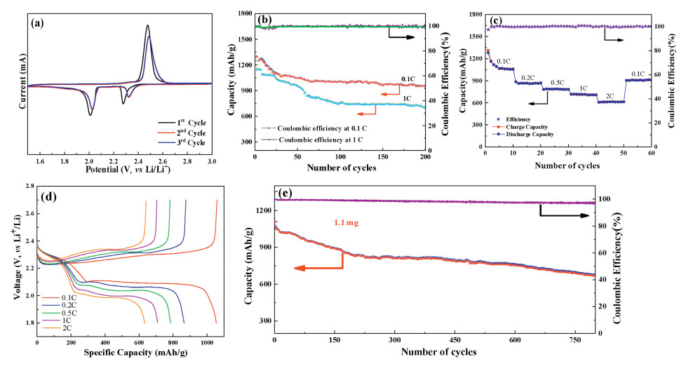
The cycling stability of cells with PP and Co9S8@PP separator and sulfur loading of 2.2 mg/cm2 were evaluated at current density of 0.1 C and 1 C for 200 cycles (Fig. 3b and Fig. S4 in Supporting information). At the current density of 0.1 C, the discharge capacity of cells with PP separator decreases drastically from 1078.1 mAh/g to 809.0 mAh/g after 200 cycles, while the discharge capacity of cells with Co9S8@PP separator declines from 1291.9 mAh/g to 951.0 mAh/g with a capacity retention ratio of 73.6% after 200 cycles, and the average capacity decay is 0.13% per cycle. The fast fading of capacity during initial cycles could be ascribed to shuttle effect caused by polysulfides. The cell with Co9S8@PP separator at 1 C possesses a high initial discharge capacity of 1255.4 mAh/g, and the discharge capacity still maintains at 701 mAh/g after 200 cycles. The capacity retention ratio and average capacity decay is 55.8% and 0.22%, respectively. It is further proved that the vertically grown nano array Co9S8 on PP separator can immobilize the polysulfides by physical-chemical effect.
The rate performance of cells with PP and Co9S8@PP separator and sulfur loading of 2.2 mg/cm2 were shown in Fig. 3c and Fig. S5 (Supporting information). Compared to the cells with PP separator, the discharge capacity of 1055 mAh/g, 866 mAh/g, 781 mAh/g, 709 mAh/g, and 612 mAh/g at the current density of 0.1 C, 0.2 C, 0.5 C, 1 C and 2 C were obtained, respectively. Most importantly, the discharge capacity of 912 mAh/g can be restored when the current density goes back to 0.1 C, suggesting the good rate performance of the cells. The galvanostatic charge-discharge profiles (Fig. 3d) in displays two discharge plateau at 2.3–2.4 V and 2.1 V, respectively, which is in accordance with the CV results. With increases of the current densities, the discharge capacity decreases.
To further investigate the electrochemical performance of the Co9S8@PP separator, the lithium sulfur batteries with Co9S8@PP separator and high sulfur loading of 4.0 mg/cm2 were assembled. Fig. 3e describes the long cycling performance of the lithium sulfur battery at 0.2 C. The initial discharge capacity of the cell with Co9S8@PP separator is 1107 mAh/g, and the relative high discharge capacity of 665 mAh/g was still remained after 800 cycles. The discharge capacity decay is about 0.049% per cycle, indicating the excellent cycling performance of the lithium sulfur batteries.
To reveal the conversion process of polysulfides on the Co9S8@PP separator, the redox behaviors of Li2S6 in symmetrical cells were tested. As shown in Fig. S6 (Supporting information), the redox current of Li2S6 in the cells with Co9S8@PP is much larger than those in the cells with PP, confirming the Co9S8 can greatly promote the redox kinetics of polysulfides conversions. The EIS measurements were performed to examine the resistance of the cells with Co9S8@PP separator. As shown in Fig. S7 (Supporting information), the depressed semicircles in the high frequency region represent the charge transfer resistance (Rct) during the electrochemical reactions, and the slope lines in the low frequency region represent the Warburg impedance caused by Li+ diffusing between electrodes interfaces. Compared to the cell with pristine PP separator, the cell with Co9S8@PP separator exhibits considerable compressed Rct, which can be ascribed to the high electric conductivity of Co9S8. From above all, the Co9S8 modified PP separator could considerably improve the redox kinetics, facilitate charge transfer, restrain polysulfides diffusion to anode, and finally enhance the stability and extend life of battery.
In order to study the interaction between S and Co9S8 more deeply, the DFT method was adopted to observe the adsorption of Li2Sn (n = 1, 2, 4, 6) species on the Co9S8 (111) surfaces. First, the structure of the lithium polysulfides cluster were optimized (Fig. S8 in Supporting information), the bond length of the structures are consistent with previous research reports [35]. Then, the models of the adsorption systems were built, the optimized structures of Li2Sn adsorbed on Co9S8 (111) surface with initial position of the clusters both parallel and vertical to the surface were shown in Fig. 4. The adsorption energy of Li2Sn on the Co9S8 (111) surface is calculated using the following equation, Ea = Etotal- (EX + ESS). Here, Etotal, EX(X = Li2Sn, n = 1, 2, 4, 6) and are the total energy of the adsorption system, molecular clusters of Li2Sn and Co9S8 (111) substrate, respectively. It can be seen that the S atoms in lithium polysulfide are bonded to Co atoms on the surface, and Li atoms in lithium polysulfide are bonded to S atoms on the surface. All the calculated adsorption energies are larger than 2 eV. With the rotation of the molecular cluster directions, the adsorption energies become higher when the contact area between the clusters and the Co9S8 surface gets larger, which is in agreement with previous studies [36]. This indicates that the chemical interaction between Li2Sn clusters with Co9S8 (111) surface is quite strong, and it can be mainly attributed to the coexistence of Co-S and Li-S bonds [35].

In order to further explore the charge transfer between Li2Sn clusters and Co9S8 (111) surface, the differential charge density of the adsorption system were also studied. It is found that electrons transfer to S atoms in the clusters via Co atoms on the Co9S8 (111) surface, and also transfer from Li atoms in the clusters to S atoms on the Co9S8 (111) surface, as shown in Fig. S9 (Supporting information). The Bader charge analysis shows that electrons in Li2Sn (n = 1, 2, 4, 6) clusters flow toward Co9S8 (111) surface after adsorption, and it is also found that the more electrons transferred from clusters to Co9S8 (111) surface, the higher the adsorption energies are, this may be because charge transferred from Li2Sn clusters to Co9S8 surface could reduce the electron density of S and Li atoms in the polysulfide, which weakens the Li-S bond in the clusters. Thus, the Co9S8 host can provide stronger chemical adsorption energies for Li2Sn clusters due to the formation of both new Co-S and Li-S bonds in the interface of the clusters and Co9S8 surface.
The electrochemical performance of cells with the Co9S8 @PP separators are largely improved, and it can be ascribed to the following aspects. Firstly, Co9S8 can absorb the lithium polysulfides by forming strong Co-S and Li-S chemical bonds, and thus alleviating the shuttle effect of the polysulfides during cycling. Secondly, the Co9S8 can accelerate the redox reaction by its catalytic effect and good electric conductivity [37-40]. Finally, the large surface area of the Co9S8 can provide more active sites for both absorption and redox reaction.
In summary, a novel Co9S8 nano-flower cluster array derived from MOF which was in-situ grown on the surface of PP separator was selected as the functional separator for high-performance lithium sulfur battery. The polar nature, large specific surface area, and the vertically aligned microstructure of the functional separator imposes a potential sulfur immobilization ability, and meanwhile, the shuttle effect of the polysulfides can be suppressed effectively by both the physical and chemical bonding between the Co 9S8 and polysulfides. This provides a facile way to construct a highly effective polysulfide barrier, and thus enhancing the electrochemical performance of lithium sulfur batteries.
The authors report no declarations of interest.
This work is supported by the Natural Science Foundation of Beijing (No. L182062), Organization Department of Beijing Talents Project (No. 2018000021223ZK21), the Yue Qi Young Scholar Project of China University of Mining & Technology (Beijing) (No. 2017QN17), the Fundamental Research Funds for the Central Universities (Nos. 2020YJSJD01, 2020XJJD01 and 2020YQJD05).
Supplementary material related to this article can be found, in the online version, at doi:https://doi.org/10.1016/j.cclet.2020.09.022.
S.T. Wang, Y. Yang, Y.H. Dong, Z.T. Zhang, Z.L. Tang, J. Adv. Ceram. 8 (2019) 1-18. doi: 10.1007/s40145-018-0292-2
D.D. Zhang, J. Li, Z. Su, et al., J. Adv. Ceram. 7 (2018) 246-255. doi: 10.1007/s40145-018-0276-2
Y. Yang, G.H. Yu, J.J. Cha, et al., ACS Nano 5 (2011) 9187-9193. doi: 10.1021/nn203436j
R.P. Fang, S.Y. Zhao, Z.H. Sun, et al., Adv. Mater. 29 (2017) 1606823. doi: 10.1002/adma.201606823
W.M. Kang, N.P. Deng, J.G. Ju, et al., Nanoscale 8 (2016) 16541-16588. doi: 10.1039/C6NR04923K
A. Manthiram, Y.Z. Fu, Y.S. Su, Acc. Chem. Res. 46 (2013) 1125-1134. doi: 10.1021/ar300179v
J. Park, S.H. Yu, Y.E. Sung, Nano Today 18 (2018) 35-64. doi: 10.1016/j.nantod.2017.12.010
X. Liu, J.Q. Huang, Q. Zhang, L.Q. Mai, Adv. Mater. 29 (2017) 1601759. doi: 10.1002/adma.201601759
M.R. Kaiser, Z.J. Han, J. Liang, S.X. Dou, J.Z. Wang, Energy Storage Mater. 19 (2019) 1-15. doi: 10.1016/j.ensm.2019.04.001
M. Shaibani, A. Akbari, P. Sheath, et al., ACS Nano 10 (2016) 7768-7779. doi: 10.1021/acsnano.6b03285
Y.W. Chen, S.Z. Niu, W. Lv, C. Zhang, Q.H. Yang, Chin. Chem. Lett. 30 (2019) 521-524. doi: 10.1016/j.cclet.2018.04.019
S.K. Liu, X.B. Hong, Y.J. Li, et al., Chin. Chem. Lett. 28 (2017) 412-416. doi: 10.1016/j.cclet.2016.10.038
T.Y. Wang, K. Kretschmer, S.H. Choi, et al., Small Methods 1 (2017) 11751-11787.
Z. Li, H.B. Wu, X.W. Lou, Energ. Environ. Sci. 9 (2016) 3061-3070. doi: 10.1039/C6EE02364A
Y. Zhong, X.H. Xia, S.J. Deng, et al., Adv. Energy Mater. 8 (2018) 1701110. doi: 10.1002/aenm.201701110
J.L. Qin, H.J. Peng, J.Q. Huang, et al., Small Methods 2 (2018) 1800100. doi: 10.1002/smtd.201800100
J.L. Qin, B.Q. Li, J.Q. Huang, et al., Mater. Chem. Front. 3 (2019) 615-619. doi: 10.1039/C8QM00645H
J.Q. Huang, Z.L. Xu, S. Abouali, M.A. Garakani, J.K. Kim, Carbon 99 (2016) 624-632. doi: 10.1016/j.carbon.2015.12.081
H. Tang, S.S. Yao, S.K. Xue, et al., Electrochim. Acta 263 (2018) 158-167. doi: 10.1016/j.electacta.2018.01.066
V.C. Hoang, V. Do, I.W. Nah, et al., Electrochim. Acta 210 (2016) 1-6. doi: 10.1016/j.electacta.2016.04.171
H.B. Lin, L.Q. Yang, X. Jiang, et al., Energ. Environ. Sci. 10 (2017) 1476-1486. doi: 10.1039/C7EE01047H
G.M. Zhou, Y.B. Zhao, A. Manthiram, Adv. Energy Mater. 5 (2015) 1402263. doi: 10.1002/aenm.201402263
L. Luo, S.H. Chung, C.H. Chang, A. Manthiram, J. Mater. Chem. A 5 (2017) 15002-15007. doi: 10.1039/C7TA05277D
X.L. Ji, K.T. Lee, L.F. Nazar, Nat. Mater. 8 (2009) 500-506. doi: 10.1038/nmat2460
Z. Zhang, L.L. Kong, S. Liu, G.R. Li, X.P. Gao, Adv. Energy Mater. 7 (2017) 1602543. doi: 10.1002/aenm.201602543
S.Q. Chen, B. Sun, X.Q. Xie, et al., Nano Energy 16 (2015) 268-280. doi: 10.1016/j.nanoen.2015.05.034
P.C. Shi, Y. Wang, X. Liang, et al., ACS Sustain. Chem. Eng. 6 (2018) 9661-9670. doi: 10.1021/acssuschemeng.8b00378
C. Deng, Z.W. Wang, S.P. Wang, J.X. Yu, J. Mater. Chem. A 7 (2019) 12381-12413. doi: 10.1039/C9TA00535H
Y.Y. Geng, Z.P. Ma, L. Su, et al., J. Alloys. Compd. 815 (2020) 152189. doi: 10.1016/j.jallcom.2019.152189
M. Rana, M. Li, X. Huang, et al., J. Mater. Chem. A 7 (2019) 6596-6615. doi: 10.1039/C8TA12066H
H.W. Wu, Y. Huang, W.C. Zhang, et al., J. Alloys. Compd. 708 (2017) 743-750. doi: 10.1016/j.jallcom.2017.03.047
J.Q. Huang, T.Z. Zhuang, Q. Zhang, et al., ACS Nano 9 (2015) 3002-3011. doi: 10.1021/nn507178a
Z.L. Xu, J.K. Kim, K. Kang, Nano Today 19 (2018) 84-107. doi: 10.1016/j.nantod.2018.02.006
Q.P. Wu, X.J. Zhou, J. Xu, F.H. Cao, C.L. Li, J. Energy Chem. 38 (2019) 94-113. doi: 10.1016/j.jechem.2019.01.005
Q.F. Zhang, Y.P. Wang, Z.W. Seh, et al., Nano Lett. 15 (2015) 3780-3786. doi: 10.1021/acs.nanolett.5b00367
Y. Chen, S.T. Lu, J. Zhou, et al., J. Mater. Chem. A 5 (2017) 102-112. doi: 10.1039/C6TA08039A
M. Zhao, H.J. Peng, B.Q. Li, et al., Angew. Chem. Int. Ed. 59 (2020) 9011-9017. doi: 10.1002/anie.202003136
J. Xie, B.Q. Li, H.J. Peng, et al., Adv. Mater. 31 (2019) 1903813. doi: 10.1002/adma.201903813
B.Q. Li, H.J. Peng, X. Chen, et al., CCS Chem. (2019) 128-137. doi: 10.31635/ccschem.019.20180016
B.Q. Li, L. Kong, C.X. Zhao, et al., InfoMat 1 (2019) 533-541. doi: 10.1002/inf2.12056

Figure 2 The morphologies of MOF@PP and Co9S8@PP. (a-c) Pristine PP separator (white), MOF@PP (dark blue) and Co9S8@PP (black). SEM images of (d) the pristine PP separator, (e) MOF@PP and (f-g) Co9S8@PP. (h-k) EDS spectra of the cobalt, sulfur and carbon.

Figure 3 (a) CV curves, (b) cycling performance, (c) rate performance, (d) galvanostatic charge-discharge profiles and (e) long cycling performance of cells with Co9S8@PP separator.

 扫一扫看文章

扫一扫关注我们
 DownLoad:

 下载:
下载:
