Figure 1.
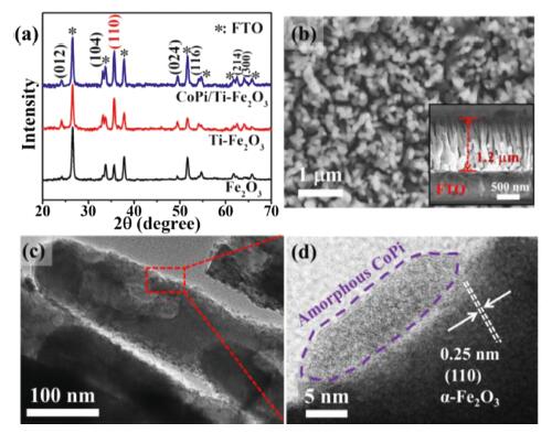
(a) XRD patterns of Fe2O3-based photoanodes. (b) Vertical-view and cross-sectional SEM, (c) TEM and (d) HRTEM images of CoPi/Ti-Fe2O3 photoanode.
Integration of Fe2O3-based photoanode and atomically dispersed cobalt cathode for efficient photoelectrochemical NH3 synthesis
Weikang Wang , Shengbo Zhang , Yanyan Liu , Li-Rong Zheng , Guozhong Wang , Yunxia Zhang , Haimin Zhang , Huijun Zhao

As an essential life building block and important carrier of hydrogen energy, ammonia (NH3) is currently synthesized by the industrial scale Haber-Bosch process [1]. However, this over a century-old Haber-Bosch process requires high temperature (400–500 ℃) and pressure (100–350 atm), consumes tremendous energy and natural gas (as the hydrogen source), and concurrently results in greenhouse gas (e.g., CO2) emission [2, 3]. Therefore, it is highly desirable to develop alternative routes for nitrogen (N2) reduction to NH3 under ambient temperature and pressure conditions. In recent years, photocatalytic, electrocatalytic and photoelectrochemical (PEC) techniques have been intensively investigated for the N2 reduction reaction (NRR) at ambient conditions, demonstrating great potentials to replace the traditional Haber-Bosch process [4, 5]. Nonetheless, it is critically important for developing high-efficiency catalysts, capable of adsorption and activation of intrinsically inert N2 molecules, as well as reasonable configuration of the catalysts in these systems for high-efficiency NH3 synthesis.
As we know, it has been widely accepted that the photocatalytic oxidation and reduction half-reactions occur at the same photocatalyst particle for a particulate suspension photocatalysis system, resulting in a rapid recombination of photogenerated carriers and thus obviously decreasing photocatalytic efficiency [6, 7]. This issue existed in the photocatalytic system can be well solved by using the PEC technique, in where a suitable potential bias is applied to a photocatalyst immobilized on a conducting substrate to allow the combination of electrochemical technique with photocatalysis and greatly minimize the charge recombination, thereby significantly increasing the photocatalytic efficiency [8, 9]. Owing to these advantages, the PEC technique has been successfully employed to water splitting to generate H2, CO2 reduction, organic compound oxidation, environmental detection and so on [8-10]. Recently, several research groups have demonstrated that N2 reduction to NH3 by the PEC technique is experimentally feasible, exhibiting high NH3 yield rate and selectivity [11, 12]. Hamers et al. reported that the illuminated hydrogen-terminated diamond under ultraviolet (UV) light in a dual-compartment H-cell can result in electron emission to produce solvated electrons in water, thus inducing NRR at ambient temperature and pressure [13]. MacFarlane and co-workers synthesized an Au nanoparticles modified p-type Si photoelectrode, achieving an NH3 yield rate of 6.0 μg h−1 cm-2 without an applied potential bias by photoelectrochemical N2 reduction under 2 sun illumination and 7 atm pressure [14]. In addition, the development of high-efficiency photocathodes in PEC technique, such as the aerophilic-hydrophilic heterostructured Si-based electrode and R-BiOI photocathode, has become another feasible means for high active and selective N2 reduction to NH3. In their studies, the synthesized Si-based and R-BiOI photocathodes have the bifunctionality of solar-light absorption and N2 adsorption/activation [12, 15]. Therefore, reasonable design of the photocathodes' composition and structure is critically important for high-efficiency PEC N2 reduction, but great challenging. Comparatively, varieties of high-efficiency photoanodes have been widely developed and fabricated for PEC applications [16]. Indeed, most of recent reported photoanodes in PEC applications are mainly focused on the oxidation half-reactions to overcome the slow reaction kinetics in water oxidation or organic oxidation [9, 17, 18]. As for the PEC N2 reduction to NH3, a high-efficiency cathodic catalyst is essential in the PEC system. Therefore, the integration of a high-performance photoanode and an efficient cathodic NRR catalyst in a PEC system can extend its N2 reduction application. However, there is no related report in literatures so far.
Herein, we report the conversion N2 into NH3 by solar-driven PEC technique, composed of high-efficiency cobalt phosphate (CoPi) modified Ti-doped Fe2O3 (CoPi/Ti-Fe2O3) nanoarrays photoanode and cobalt single-atom catalyst (Co-SAC) constructed cathode. As shown in Scheme S1 (Supporting information), the fabricated CoPi/Ti-Fe2O3 photoanode under a suitable potential bias and solar light irradiation is responsible for the oxidation half-reaction in alkaline media, namely, oxidation of H2O/OH– to release O2, and meanwhile the photogenerated electrons under suitable potential bias transfer to the Co-SAC cathode to attack the adsorbed N2 on the Co-SAC, thus yielding NH3. As a result, such solar-driven PEC-NRR system can achieve an NH3 yield rate of 1021.5 μg mgCo−1 h−1 and faradic efficiency (FE) of 11.9% at an applied bias of 1.2 V versus reversible hydrogen electrode (vs. RHE) on photoanode in 0.2 mol/L NaOH electrolyte. The high NH3 synthesis performance using such solar-driven PEC-NRR system can be attributed to the developed high-efficiency CoPi/Ti-Fe2O3 photoanode and Co-SAC cathode to overcome the slow reaction kinetics of anode H2O oxidation, provide abundant photoelectrons and N(O)-coordinated Co active sites for N2 adsorption/activation, leading to an efficient conversion of N2 to NH3.
In this work, we employed a facile hydrothermal method to fabricate FeOOH nanoarrays on FTO conductive glass [19], followed by chemical vapor deposition (CVD) of TiCl4 and thermal tre atment to obtain Ti doped Fe2O3 nanoarrays (denoted as Ti-Fe2O3) [20]. For comparison, the pure Fe2O3 nanoarrays on FTO substrate (denoted as Fe2O3) were also fabricated by thermal tre atment of FeOOH nanoarrays. Subsequently, CoPi modified Ti-Fe2O3 (CoPi/Ti-Fe2O3) nanoarrays photoanode was fabricated by a photoassisted deposition method [19]. In this study, the aim of Ti doping and CoPi modification in Fe2O3 nanoarrays is to promote the charge conductivity and water oxidation efficiency of photoanode, respectively, thus enhancing the PEC efficiency of photoanode [17, 21, 22].
Fig. 1a shows the XRD patterns of Fe2O3, Ti-Fe2O3 and CoPi/Ti-Fe2O3 samples. The diffraction peaks at 2θ = 26.6°, 33.8°, 37.9°, 51.7°, 54.6°, 61.7° and 65.8° for these three samples can be due to SnO2 (JCPDS No. 41-1445) from FTO substrate. Besides of SnO2 diffraction peaks, the XRD patterns of Fe2O3 sample exhibit several diffraction peaks at 2θ = 24.1°, 33.1°, 35.6°, 49.5°, 54.2°, 62.5° and 64.1°, ascribed to the hematite structured α-Fe2O3 (JCPDS No. 33-0664) [17, 23]. After Ti doping and CoPi modification, no new diffraction peaks can be observed for the Ti-Fe2O3 and CoPi/Ti-Fe2O3 samples compared with the Fe2O3 sample, indicating the dominant α-Fe2O3 phase in these samples. For these three samples, the (110) diffraction peak of α-Fe2O3 is predominant, revealing an obvious preferential orientation for [110] axis vertical to the FTO substrate [24]. As indicated in previous works, the preferential orientation of (110) is favourable for the electron mobility along this axis relative to other axis in hematite [25, 26]. The improvement of electron mobility would contribute to improving PEC current density and suppress the photogenerated charge recombination [27, 28], thus promoting the PEC efficiency of catalyst [26]. In Fig. 1a, it can be clearly found that the (110) diffraction peak becomes stronger after Ti doping in Fe2O3, meaning more superior electron mobility, beneficial for the separation of photogenerated carriers, thus improving the PEC efficiency of photoanodes [29, 30], as also revealed in previous work [31]. In addition, the Raman spectra measurement results (Fig. S1 in Supporting information) demonstrate that these three samples all exhibit seven Raman-active vibration modes (2A1g+5Eg), assigned to hematite structured α-Fe2O3 [19]. It is noteworthy that the Raman peak at ~663 cm–1 is ascribed to the longitudinal optical (LO) mode of Fe2O3, resulted from the breakdown of Raman space symmetry and activation of extra modes induced by lattice defects and surface defects [32]. Clearly, the peak intensities of LO mode of Ti-Fe2O3 and CoPi/Ti-Fe2O3 become stronger compared to Fe2O3, suggesting the increased defects in Ti doped samples, possibly favourable for improving their PEC performance [21, 26]. Fig. 1b shows the surface SEM image of CoPi/Ti-Fe2O3, exhibiting well-aligned Fe2O3-based nanoarrays perpendicular to the FTO substrate. The cross-sectional SEM image (inset in Fig. 1b) displays the nanoarrays film thickness of ~1.2 μm and the nanorod diameter of ~90 nm, respectively. The elemental mapping images (Fig. S2 in Supporting information) of CoPi/Ti-Fe2O3 indicate the presence of Fe, O, Co, Ti, Sn and P, implying successful fabrication of CoPi modified Ti-doped Fe2O3. The low-magnification TEM image (Fig. 1c) further confirms the formation of CoPi/Ti-Fe2O3 nanorod structure. Importantly, the HRTEM image (Fig. 1d) of an individual CoPi/Ti-Fe2O3 nanorod indicates that the amorphous CoPi layer contacts closely to Fe2O3 rod, and the lattice spacing of 0.25 nm can be indexed to the (110) plane of α-Fe2O3, well coincided with the XRD results.
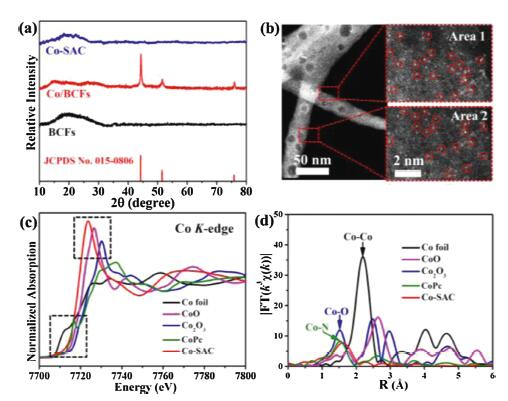
The fabricated CoPi/Ti-Fe2O3 can be used as the photoanode for PEC oxidation half-reaction in aqueous electrolyte to boost reaction kinetics of water oxidation [19, 22] and supply photogenerated electrons for NRR in cathode. However, to realize the PEC-NRR application in CoPi/Ti-Fe2O3 involved photoelectrochemical system, an efficiency cathodic NRR catalyst is also necessary. Recently, Au, Ru, Fe, Mo, Co and Cu single-atom catalysts have been developed for electrocatalytic NRR, exhibiting high NRR to NH3 performance [33-39]. In this work, our aim is to integrate high-efficiency CoPi/Ti-Fe2O3 photoanode with an efficient electrocatalyst cathode for the PEC NRR application. Therefore, we utilized bacterial cellulose (BC) as the adsorption regulator to synthesize Co single-atom catalyst (Co-SAC). The BC precursor exhibits uniform fiber-like structure and possesses surface-rich O-containing functional groups (Fig. S3 in Supporting information). Through three-step synthetic processes including adsorption, pyrolysis and acid etching tre atment, atomically dispersed Co on BC converted graphitic carbon can be achieved. Fig. 2a shows the XRD patterns of the as-synthesized Co-SAC, only exhibiting a broad diffraction peak centered at 2θ = 20°, owing to the graphitic carbon. No diffraction peaks of metallic Co and cobalt oxides can be observed in the XRD patterns, possibly meaning the formation of atomically dispersed Co on BC converted graphitic carbon. To further confirm this, the aberration-corrected high-angle annular dark-field scanning transmission electron microscopes (HAADF-STEM) characterization of Co-SAC was performed to elucidate the distribution details of Co species. The HAADF-STEM images (Fig. 2b) indicate that no Co-related particles can be observed and Co atoms are homogeneously dispersed on the surface of BC converted graphitic carbon, confirming atomically dispersed nature of the formed Co. In addition, the X-ray absorption near-edge structure (XANES) and Fourier transformed (FT) k3-weighted extended X-ray absorption fine structure (EXAFS) spectra were carried out to further clarify the detailed structural information on single atomic Co in Co-SAC. The normalized Co K-edge XANES spectra (Fig. 2c) indicate that the presence of metallic Co° in Co-SAC can be excluded by the different pre-edge feature from that of the referenced Co foil [40]. Moreover, the onset energy (~7710 eV) of Co K-edge absorption gradually grows higher from Co foil to Co2O3, revealing a change of the valence state from 0 to +3 in the referenced samples of Co foil and cobalt oxides (e.g., CoO and Co2O3). In XANES spectra (Fig. 2c), the onset energy and absorption line for Co-SAC are situated between those for Co foil and CoO, confirming its electronic structure of Coφ+ (0 < φ < 2). Additionally, it should be also noted that the white line peak (> 7720 eV) for Co-SAC exhibits lower energy than that of CoO (Co2+), further revealing the valence state of Co atoms in Co-SAC is situated between 0 and +2 [41]. Moreover, no Co-Co scattering (dominated in Co foil) path at ~2.19 Å can be observed in the FT EXAFS spectrum of R space (Fig. 2d) for Co-SAC, again confirming the formation of single atomic Co. More importantly, the EXAFS spectrum of Co-SAC shows a strong peak centered at ~1.59 Å close to the Co-N coordination (~1.54 Å) in cobalt phthalocyanine (CoPc) and Co-O coordination (~1.53 Å) in Co2O3, suggesting that Co single atoms in Co-SAC could coordinate with N and/or O atoms to form CoNx and/or CoOx species. These formed single atomic Co sites were predicted to be electrocatalytically active for NRR by first-principles calculation [42]. With the aid of quantum physics, most of material properties (chemical, catalytic, electrical, magnetic, optical, etc.) and corresponding chemical reactions can, in principle, be predicted from the atomic number and mass of the atomic species by the first-principles calculation. Based on the first-principles calculation, the density functional theory (DFT) computations results indicated that a series of metal SACs, including Co, Mo, Ti, W and Pt, are promising candidates for NRR catalysts [43]. Fig. S4a (Supporting information) presents the surface survey XPS spectrum of Co-SAC, indicating the presence of C (83.7 at%), O (15.3 at%), N (0.6 at%) and Co (0.4 at%). Meanwhile, the high-resolution XPS spectra of O 1s, N 1s and Co 2p are shown in Figs. S4b-d (Supporting information). It indicates that there are abundant oxygen-containing functional groups (including O-C=O and -OH) and slight nitrogen-species (including graphitic N, pyrrolic N and pyridinic N atoms) in the Co-SAC sample, which can act as available supports for metal single atoms [44, 45]. However, the XPS signals of Co 2p are very weak, coincided with the absent signal for Co-O or Co-N bonds in O 1s or N 1s XPS spectra, owing to the low loading amount of Co single-atoms. In this work, single atomic Co content in Co-SAC was determined to be 1.2 wt% by the inductively-coupled plasma optical emission spectroscopy (ICP-OES) technique.
In a PEC-NRR system integrated of CoPi/Ti-Fe2O3 photoanode and Co-SAC cathode, the NRR performance of Co-SAC is highly dependent on the performance of CoPi/Ti-Fe2O3 photoanode. Therefore, we firstly investigated the optical properties of the as-synthesized CoPi/Ti-Fe2O3 photoanode. Fig. 3a shows the UV–vis diffuse reflection spectra (DRS) of Fe2O3, Ti-Fe2O3 and CoPi/Ti-Fe2O3 samples. The calculated bandgap is 2.09 eV, 2.05 eV and 2.05 eV for Fe2O3, Ti-Fe2O3 and CoPi/Ti- Fe2O3 based on the DRS, respectively (Fig. 3b). Obviously, Ti doping in Fe2O3 results in narrower bandgap than that of pristine Fe2O3, meaning its better visible-light harvesting capacity [17, 46]. Moreover, the CoPi modification on Ti-Fe2O3 has not significant influence on its bandgap, still exhibiting superior visible light absorption property for CoPi/Ti-Fe2O3, favourable for high PEC performance. Fig. 3c shows the incident photon-to-current efficiency (IPCE) curves of Fe2O3, Ti-Fe2O3 and CoPi/Ti-Fe2O3 measured at 1.23 V (vs. RHE in 0.2 mol/L NaOH solution) under simulated sunlight irradiation (AM 1.5 G, 100 mW/cm2). The results reveal that CoPi/Ti-Fe2O3 possesses the highest IPCE value of ~35% at a wavelength of 370 nm, and its IPCE is over ~10% in wider wavelength range from 300 nm to 500 nm, indicating that Ti doping and CoPi modification can afford high PEC performance of Fe2O3 photoelectrode [25].
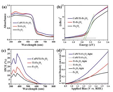
The Mott-Schottky (M-S) analysis was subsequently performed to identify the charge transfer property and carrier density of all investigated photoanodes. In Fig. S5 (Supporting information), the M-S curves of all measured electrodes exhibit positive slopes, manifesting that these three photoelectrodes are typical n-type semiconductors that are suitable for application as photoanodes. Moreover, the carrier densities of Fe2O3, Ti-Fe2O3 and CoPi/Ti-Fe2O3 photoelectrodes were calculated to be 4.27×10¹⁹, 1.97×10²⁰ and 2.94×1020 cm−3, respectively, and their carrier densities can be further enhanced with light irradiation, as listed in Table S1 (Supporting information). The results show that the CoPi/Ti-Fe2O3 photoelectrode under light irradiation possesses the largest carrier density of 4.65×1020 cm−3 among all investigated photoelectrodes, indicating its superior electrical conductivity and charge separation efficiency, resulted from Ti doping and CoPi modification [47, 48]. The high carrier density in CoPi/Ti-Fe2O3 photoelectrode contributes to its high PEC performance. Fig. 3d shows the relationship of the photocurrent density (J) and applied potential bias (V) of Fe2O3, Ti-Fe2O3 and CoPi/Ti-Fe2O3 photoelectrodes with and without light irradiation in 0.2 mol/L NaOH solution. For all cases, without light irradiation, no photocurrent can be observed, while the photocurrent is increased with applied potential bias under light irradiation for all photoelectrodes. Comparatively, the CoPi/Ti-Fe2O3 photoelectrode shows larger photocurrent in the investigated potential range than that of Fe2O3 and Ti-Fe2O3 photoelectrodes, meaning its higher PEC oxidation efficiency owing to Ti doping and CoPi modification [22, 49]. Importantly, it can be seen from Fig. 3d, the pristine Fe2O3 photoelectrode shows an onset potential of ~0.9 V (vs. RHE), while after Ti doping, the onset potential of Ti-Fe2O3 photoelectrode positively shifts ~100 mV compared to the Fe2O3 photoelectrode, consistent with the reported work [47]. This is mainly ascribed to the additional donor level induced by Ti doping, which influences the band bending at the semiconductor/electrolyte interface [29, 47]. Moreover, the theoretical studies have also revealed that larger overpotential is required for PEC oxidation of water using Ti doped hematite [50]. Thus, CoPi was employed as the oxygen evolution reaction (OER) co-catalyst in this work to reduce surface kinetic barriers and negatively shift the onset potential of water oxidation (around 100–150 mV) [19, 51]. As a result, the CoPi modified Ti-Fe2O3 photoelectrode exhibits an onset potential of ~0.9 V (vs. RHE), identical to that of Fe2O3 photoelectrode. The Ti doping and CoPi modification synergistically enhance the PEC performance of Fe2O3 photoelectrode, mainly due to the improved electron conductivity, accelerated photogenerated carriers transfer and reduced surface kinetic barriers of water oxidation [19, 29].
Subsequently, we evaluated the PEC NRR performance using CoPi/Ti-Fe2O3 photoanode and Co-SAC cathode integrated in a photoelectrochemical cell (Scheme S1). Fig. S6 (Supporting information) shows the photograph of photoelectrochemical cell composed of CoPi/Ti-Fe2O3 photoanode and Co-SAC cathode. Prior to all measurements, 14N2 (or 15N2) feeding gas was pre-treated using 0.01 mol/L H2SO4 solution and distilled water to eliminate any environmental NH3 interferences [52]. Then, the used N2 tail gas passing through the cathodic compartment was absorbed by two series of 0.01 mol/L H 2SO4 solution to avoid the loss of NH3 analyzed by the indophenol blue method (Fig. S7 in Supporting information) [53]. Using this photoelectrochemical system, the yielded NH3 from PEC NRR on Co-SAC cathode was quantitatively preliminary experimental results demonstrate that the NH3 product yielded can be detected in the samples obtained from the cathodic compartment and tail gas absorption solution. Therefore, the NH3 yield is the collective amount of the NH3 produced from the cathodic compartment and tail gas absorption solution in this work. Fig. 4a shows the dependence of the NH3 yield rate and faradaic efficiency (FE) on different applied potential bias employed on the CoPi/Ti-Fe2O3 photoanode in 0.2 mol/L NaOH electrolyte under AM 1.5 G simulated solar light irradiation of 1 h (light intensity of 100 mW/cm2). The corresponding photocurrent density curves are shown in Fig. 4b. The results demonstrate that the largest NH3 yield rate can achieved to be 1021.5 μg mgCo-1 h-1 (12.26 μg mgcat.-1 h-1) with the highest FE of 11.9% on Co-SAC cathode at an applied potential bias of 1.2 V (vs. RHE) on photoanode, which is comparable to recently reported single-atomic NRR catalysts (Table S2 in Supporting information). With further increasing potential bias, the photocurrent density is obviously enhanced (Fig. 4b), but the NH3 yield rate and FE are both decreased, mainly attributed to the competitive hydrogen evolution reaction (HER) concurrently happened on the Co-SAC cathode [39, 53]. For comparison, we also performed the experiment at open-circuit potential (OCP) condition under AM 1.5 G simulated solar-light irradiation of 1 h, the yielded NH3 is almost undetectable (Fig. 4a and Fig. S8 in Supporting information). The above result suggests that the photoelectrocatalytic approach by employing a potential bias on the CoPi/Ti-Fe2O3 can dramatically enhance its photogenerated charge transfer efficiency [54], thus improving the NRR performance on the Co-SAC. Additionally, we also compared the PEC NRR performance on the Co-SAC cathode using Fe2O3 and Ti-Fe2O3 photoanode at 1.2 V (vs. RHE) in 0.2 mol/L NaOH solution under AM 1.5 G simulated solar light irradiation of 1 h. As shown in Fig. S9 (Supporting information), the NH3 yield rate is 371.4 and 422.4 μg mgCo-1h-1 with FE of 4.5% and 11.1% on the Co-SAC cathode using the Fe2O3 and Ti-Fe2O3 photoanode, respectively, obviously lower than that (1021.5 μg mgCo-1h-1 with FE of 11.9%) on the Co-SAC cathode using the CoPi/Ti-Fe2O3 photoanode, indicating that the CoPi/Ti-Fe2O3 photoanode possesses higher PEC performance. To confirm the yielded NH3 resulted from the Co-SAC cathode in this solar-driven CoPi/Ti-Fe2O3 photoanode involved PEC system, several control experiments were also conducted in this work. As shown in Fig. S8, the yielded NH3 is ignorable when the experiments were carried out in N2-saturated 0.2 mol/L NaOH solution without Co-SAC catalyst at a potential bias of 1.2 V (vs. RHE) on photoanode with light irradiation (denoted as blank) and with Co-SAC catalyst and light irradiation but under open-circuit condition (denoted as open-circuit). In addition, when the experiments were carried out in Ar-saturated 0.2 mol/L NaOH solution with Co-SAC catalyst at a potential bias of 1.2 V (vs. RHE) on photoanode (denoted as Ar-saturated electrolyte), the measurable NH3 is also ignorable. The above control experimental results indicate that the yielded NH3 is from the NRR on Co-SAC cathode in the solar-driven CoPi/Ti-Fe2O3 photoanode involved PEC system without any noticeable environmental interference. To further confirm this, the isotopic labeling experiments were subsequently conducted using 14N2 and 15N2 as the feeding gases in 0.2 mol/L NaOH solution at an applied potential bias of 1.2 V (vs. RHE) on photoanode for 1 h PEC-NRR period [53]. Then we analyzed qualitatively and quantitatively the 1H nuclear magnetic resonance (NMR) spectra of the samples [55]. Based on the NMR spectra of 14NH4+ and 15NH4+ standards, the corresponding calibration curves are shown in Fig. S10 (Supporting information). The experimental results (Fig. 4c) show that the yielded concentration of 14NH4+ and 15NH4+ calculated by 1H NMR is 1.21 and 1.33 μg/mL, respectively, nearly identical with the determined values (1.26 μg/mL for 14NH4+ and 1.38 μg/mL for15NH4+) by the indophenol blue method. The almost identical 14NH4+ and 15NH4+ concentrations determined by both methods categorically demonstrate that the yielded NH3 is indeed originated from the Co-SAC catalyzed NRR in the solar-driven CoPi/Ti-Fe2O3 photoanode involved PEC system.
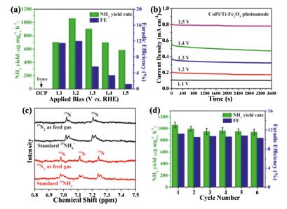
The recycling stability of the PEC-NRR system is tested as shown in Fig. 4d. Employing an applied potential bias of 1.2 V (vs. RHE) on CoPi/Ti-Fe2O3 photoanode with light irradiation, the NH3 yield rate and FE on Co-SAC cathode in 0.2 mol/L NaOH solution can be well maintained after 6 consecutive cycles. After 6 cycles of measurements, the collected cathode electrocatalyst (labeled as Co-SAC-used) was characterized by the XRD and HAADF-STEM techniques. The XRD characterization results (Fig. S11a in Supporting information) reveal that only one broad peak centered at 2θ = 20° ascribed to the graphitic carbon can be detected and no characteristic peaks derived from metallic Co nanoparticles are detectable, similar to that of pristine Co-SAC catalyst (Fig. 2a). Moreover, the HAADF-STEM image (Fig. S11b in Supporting information) of the Co-SAC-used still shows atomically dispersed nature of Co on the BC converted graphitic carbon. The above results indicate that the Co-SAC possesses high stability, favourable for high-efficiency PEC-NRR to NH3.
In summary, we developed a photoelectrochemical N2 reduction system integrated of CoPi/Ti-Fe2O3 photoanode and Co-SAC cathode. Utilizing such PEC-NRR system, the NH3 yield rate on Co-SAC cathode can be achieved to be 1021.5 μg mgCo−1 h−1 with a faradic efficiency of 11.9% at an applied potential bias of 1.2 V (vs. RHE) in 0.2 mol/L NaOH electrolyte under simulated solar irradiation. The high PEC-NRR to NH3 performance can be resulted from high-efficient CoPi/Ti-Fe2O3 photoanode providing abundant photoelectrons and Co-SAC catalyst supplying electrocatalytically active Co-N(O)x sites for N2 adsorption and activation. The findings in this work demonstrate the feasibility of integrating high-efficiency photoanode and efficient NRR catalyst cathode for solar-driven PEC-NRR to NH3 application.
The authors declare that they have no known competing financial interests or personal relationships that could have appeared to influence the work reported in this paper.
This work was financially supported by the National Natural Science Foundation of China (Nos. 51872292 and 51672277) and the CAS/SAFEA International Partnership Program for Creative Research Teams of Chinese Academy of Sciences, China. The authors would like to thank the 1W1B station for XAFS measurements in the Beijing Synchrotron Radiation Facility (BSRF).
Supplementary material related to this article can be found, in the online version, at doi:https://doi.org/10.1016/j.cclet.2020.04.013.
C. Guo, J. Ran, A. Vasileff, et al., Energy Environ. Sci. 11 (2017) 45-56.
C. Zhao, S. Zhang, M. Han, et al., ACS Energy Lett. 4 (2019) 377-383. doi: 10.1021/acsenergylett.8b02138
W. Wang, H. Zhang, S. Zhang, et al., Angew. Chem. Int. Ed. 58 (2019) 377-383.
C. Na, G. Zheng, Nano Res. 11 (2018) 2992-3008. doi: 10.1007/s12274-018-1987-y
X. Chen, N. Li, Z. Kong, et al., Mater. Horiz. 5 (2017) 9-27. doi: 10.30612/hre.v5i9.7710
H. Zhang, X. Liu, Y. Li, et al., J. Mater. Chem. 22 (2012) 2465-2472. doi: 10.1039/C2JM15546J
H. Zhang, X. Liu, Y. Wang, et al., J. Mater. Chem. A 1 (2013) 2646-2652. doi: 10.1039/c2ta00819j
J.H. Kim, G. Magesh, H.J. Kang, et al., Nano Energy 15 (2015) 153-163. doi: 10.1016/j.nanoen.2015.04.022
M.S. Koo, K. Cho, J. Yoon, et al., Environ. Sci. Technol. 51 (2017) 6590-6598. doi: 10.1021/acs.est.7b00774
M. Grätzel, Nature 414 (2001) 338. doi: 10.1038/35104607
K. Ithisuphalap, H. Zhang, L. Guo, et al., Small Methods 3 (2019) 1800352. doi: 10.1002/smtd.201800352
J. Zheng, Y. Lyu, M. Qiao, et al., Chemistry 5 (2019) 617-633. doi: 10.1016/j.chempr.2018.12.003
D. Zhu, L. Zhang, R.E. Ruther, et al., Nat. Mater. 12 (2013) 836. doi: 10.1038/nmat3696
M. Ali, F. Zhou, K. Chen, et al., Nat. Commun. 7 (2016) 11335. doi: 10.1038/ncomms11335
Y. Bai, H. Bai, K. Qu, et al., Chem. Eng. J. 362 (2019) 349-356. doi: 10.1016/j.cej.2019.01.051
S. Kment, F. Riboni, S. Pausova, et al., Chem. Soc. Rev. 46 (2017) 3716-3769. doi: 10.1039/C6CS00015K
J. Xie, P. Yang, X. Liang, et al., ACS Appl. Energy Mater. 1 (2018) 2769-2775. doi: 10.1021/acsaem.8b00445
B. Moss, F.S. Hegner, S. Corby, et al., ACS Energy Lett. 4 (2018) 337-342.
P. Kuang, L. Zhang, B. Cheng, et al., Appl. Catal. B 218 (2017) 570-580. doi: 10.1016/j.apcatb.2017.07.002
J. Deng, X. Lv, J. Liu, et al., ACS Nano 9 (2015) 5348-5356. doi: 10.1021/acsnano.5b01028
O. Zandi, B.M. Klahr, T.W. Hamann, Energy Environ. Sci. 6 (2013) 634-642. doi: 10.1039/C2EE23620F
B. Klahr, S. Gimenez, F. Fabregat-Santiago, et al., J. Am. Chem. Soc. 134 (2012) 16693-16700. doi: 10.1021/ja306427f
Y. Zeng, Y. Han, Y. Zhao, et al., Adv. Energy Mater. 5 (2015) 1402176. doi: 10.1002/aenm.201402176
A. Kay, I. Cesar, M. Grätzel, J. Am. Chem. Soc. 128 (2006) 15714-15721. doi: 10.1021/ja064380l
P. Zhang, A. Kleiman-Shwarsctein, Y.S. Hu, et al., Energy Environ. Sci. 4 (2011) 1020-1028. doi: 10.1039/c0ee00656d
N. Mirbagheri, D. Wang, C. Peng, et al., ACS Catal. 4 (2014) 2006-2015. doi: 10.1021/cs500372v
Y. Zhang, S. Jiang, W. Song, et al., Energy Environ. Sci. 8 (2015) 1231-1236. doi: 10.1039/C4EE03803G
Z. Liu, W. Yun, W. Bo, et al., Int. J. Hydrogen Energy 38 (2013) 10226-10234. doi: 10.1016/j.ijhydene.2013.06.028
J. Deng, J. Zhong, A. Pu, et al., J. Appl. Phys. 112 (2012) 084312. doi: 10.1063/1.4759278
N.T. Hahn, C.B. Mullins, Chem. Mater. 22 (2010) 6474-6482. doi: 10.1021/cm1026078
P. Liao, M.C. Toroker, E.A. Carter, Nano Lett 11 (2011) 1775-1781. doi: 10.1021/nl200356n
M. Einert, R. Ostermann, T. Weller, et al., J. Mater. Chem. A 4 (2016) 18444-18456. doi: 10.1039/C6TA06979G
L. Han, X. Liu, J. Chen, et al., Angew. Chem. Int. Ed. 58 (2019) 2321-2325. doi: 10.1002/anie.201811728
M. Wang, S. Liu, T. Qian, et al., Nat. Commun. 10 (2019) 341. doi: 10.1038/s41467-018-08120-x
F. Lü, S. Zhao, R. Guo, et al., Nano Energy 61 (2019) 420-427. doi: 10.1016/j.nanoen.2019.04.092
W. Zang, T. Yang, H. Zou, et al., ACS Catal. 9 (2019) 10166-10173. doi: 10.1021/acscatal.9b02944
Z. Geng, Y. Liu, X. Kong, et al., Adv. Mater. 30 (2018) 1870301. doi: 10.1002/adma.201870301
H. Tao, C. Choi, L.X. Ding, et al., Chemistry 5 (2019) 204-214. doi: 10.1016/j.chempr.2018.10.007
X. Wang, W. Wang, M. Qiao, et al., Sci. Bull. 63 (2018) 1246-1253. doi: 10.1016/j.scib.2018.07.005
B. Henne, V. Ney, K. Ollefs, et al., Sci. Rep. 5 (2015) 16863. doi: 10.1038/srep16863
P. Yin, T. Yao, Y. Wu, et al., Angew. Chem. Int. Ed. 55 (2016) 10800-10805. doi: 10.1002/anie.201604802
L. Zhang, W. Zhao, W. Zhang, et al., Nano Res. 12 (2019) 1181-1186. doi: 10.1007/s12274-019-2378-8
Z. Chen, J. Zhao, C.R. Cabrera, et al., Small Methods 3 (2019) 1800368. doi: 10.1002/smtd.201800368
Y. Liu, Q. Xu, X. Fan, et al., J. Mater. Chem. A 7 (2019) 26358-26363. doi: 10.1039/C9TA10382A
B. Huang, N. Li, W.-J. Ong, et al., J. Mater. Chem. A 7 (2019) 27620-27631. doi: 10.1039/C9TA09776G
K.D. Malviya, D. Klotz, H. Dotan, et al., J. Phys. Chem. C 121 (2017) 4206-4213. doi: 10.1021/acs.jpcc.7b00442
Z. Wang, G. Liu, C. Ding, et al., J. Phys. Chem. C 119 (2015) 19607-19612. doi: 10.1021/acs.jpcc.5b04892
M.R. Nellist, J. Qiu, F.A. Laskowski, et al., ACS Energy Lett. 3 (2018) 2286-2291. doi: 10.1021/acsenergylett.8b01150
Z. Fan, Z. Xu, S. Yan, et al., J. Mater. Chem. A 5 (2017) 8402-8407. doi: 10.1039/C7TA01430A
M.C. Toroker, J. Phys, Chem. C 118 (2016) 23162-23167.
M.W. Kanan, D.G. Nocera, Science 321 (2008) 1072-1075. doi: 10.1126/science.1162018
F. Zhou, L.M. Azofra, M. Ali, et al., Energy Environ. Sci. 10 (2017) 2516-2520. doi: 10.1039/C7EE02716H
Y. Liu, M. Han, Q. Xiong, et al., Adv. Energy Mater. 9 (2019) 1803935. doi: 10.1002/aenm.201803935
M.D. Bhatt, J.S. Lee, J. Mater. Chem. A 3 (2015) 10632-10659. doi: 10.1039/C5TA00257E
X. Li, T. Li, Y. Ma, et al., Adv. Energy Mater 8 (2018) 1801357. doi: 10.1002/aenm.201801357

Figure 1 (a) XRD patterns of Fe2O3-based photoanodes. (b) Vertical-view and cross-sectional SEM, (c) TEM and (d) HRTEM images of CoPi/Ti-Fe2O3 photoanode.

Figure 2 (a) XRD patterns of BCFs, Co/BCFs and Co-SAC. (b) HAADF-STEM image and selected-area magnified HAADF-STEM images with bright SA-Co marked in red circles of Co-SAC. (c) Normalized Co K-edge XANES spectra and (d) FT k3-weighted EXAFS spectra of Co-SAC and reference samples.

Figure 3 (a) UV–vis DRS, (b) Bandgap determination via Tauc plots, (c) IPCE (measured under 1.23 V vs. RHE) and (d) LSV under light irradiation (5 mV/s) of Fe2O3-based photoanodes.

Figure 4 (a) PEC-NRR performance on Co-SAC with different applied bias on CoPi/Ti-Fe2O3 photoanode and (b) corresponding operating photo-current density (J) vs. time (t). (c) 1H NMR spectra of the yielded 14NH4+ and 15NH4+ from 14N2 and 15N2 feed gases, and standards (all standard concentration of 10 μg/mL); (d) NH3 yield rate and FE stability on Co-SAC with CoPi/Ti-Fe2O3 NAs photoanode (applied bias of 1.2 V vs. RHE in 0.2 mol/L NaOH).

 扫一扫看文章

扫一扫关注我们
 DownLoad:
 下载:
下载: