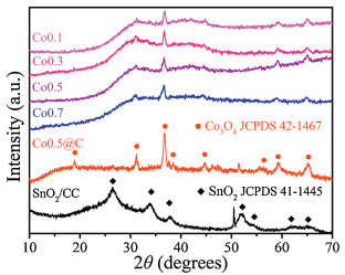
Figure 1.
XRD patterns of the different Co3O4, Co3O4@C anodes and SnO2/CC cathode.
Degradation of 4-nitrophenol by electrocatalysis and advanced oxidation processes using Co3O4@C anode coupled with simultaneous CO2 reduction via SnO2/CC cathode
Meng Zhu , Longshuai Zhang , Shanshan Liu , Dengke Wang , Yuancheng Qin , Ying Chen , Weili Dai , Yuehua Wang , Qiuju Xing , Jianping Zou

With the rapid development of society and economy, the environment on which human beings depend for survival is getting worse and worse [1], the greenhouse effect and water pollution problems are extremely serious [2-6]. Organic wastewater contains a large amount of toxic organic matter, which will accumulate in the natural environment, and finally endanger human health and existence of biology [7, 8]. Therefore, the treatment of organic wastewater is a hot topic [9-11].
There were many methods for wastewater treatment [12-15], such as Fenton [16-18], electrochemical [19-24], AOPs [25-28]. Recently, advanced oxidation processes (AOPs) based on SO4·- have rapidly developed and become emerging technologies for efficient treatment of organic pollutants. Especially, SO4·- -AOPs (SR-AOPs) based on the variable valent metal activated persulfate have received extensive attention, including cobalt oxide (Co3O4 and Co(OH)2, etc.) [29-33], manganese oxides (MnO2 and Mn3O4, etc.) [34-36] and iron oxides (Fe2O3 and Fe3O4, etc.) [36-38]. However, the current organic wastewater treatment mainly considered organic detoxification or mineralization, they did not consider resource utilization [39-42]. Under certain conditions, high concentration organic wastewater is an available resource [43]. The large amount of CO2 would be produced by the mineralization of high-concentration organic wastewater, leading to secondary pollution of greenhouse effect. Therefore, it is urgent to develop a new technology to achieve advanced treatment and simultaneous resource utilization of organic wastewater.
Recently, our group had developed some methods to realize the mineralization treatment and simultaneous resource utilization of organic wastewater. The photocatalytic method was firstly developed to realize this goal, but the products of photoreduction of CO2 (methanol and ethanol) could be easily oxidized again during the process of photocatalysis [44, 45]. In order to conquer this defect, electrocatalysis was combined with AOPs to fulfil one-pot conversion of organic pollutants into liquid fuels [46]. In this system, the electrocatalytic process was firstly coupled with SR-AOPs for the degradation of 4-NP, while the as-produced CO2 was converted into CH3OH and C2H5OH by electrocatalytic reduction. However, there were some problems in this technology. For example, the removal efficiency of organic pollutant and Faraday efficiency (FE) were still low, and the cathode of CuO could be easily reduced to Cu.
Herein, a 3D gear-shaped Co3O4@C anode was designed and prepared for efficient degradation of organic pollutants. In addition, a new sheet-like SnO2/CC cathode was prepared to achieve electrocatalytic CO2 reduction, which could reduce the overpotential and increase the FE. This novel electrocatalytic system coupled with SR-AOPs was constructed to achieve high-efficient degradation of 4-NP and reduction of CO2. Finally, the catalytic mechanism was proposed to illuminate the electro-catalytic processes involved in the one-pot conversion of 4-NP to useful chemical products, and the synergetic effects between AOPs and electrocatalysis, as well as electrocatalytic oxidation and electrocatalytic reduction.
During the experiments, analytical grade reagents and chemicals were used without further purification. The detailed information of the chemicals and the detailed preparation processes of 3D hexagram Co3O4@C anode and sheet-like SnO2/CC cathode were available in Text S1 (Supporting information). And the detailed information of analytical methods and characterizations of the as-prepared electrodes were available in Text S2 (Supporting information). Degradation of hydroxylbenzoic acid (HBA) by electrocatalysis and AOPs was carried out at potentiostatic conditions at room temperature (25 3 C) in H-type cell, in which a piece of Nafion 117 membrane was used as a separator. Ag/AgCl was the reference electrode, while Pt foil and as-prepared Co0.5@C were used as cathode and anode, respectively. The electrolytes used in the anodic and cathodic were 0.1 mol/L Na2SO4·- with 1.44 mmol/L HBA (60 mL) and 0.1 mol/L KHCO3 (60 mL), respectively. And appropriate amount of peroxymonosulfate (PMS) was added to the reactor of anodic before the catalytic reaction. The potential was set at 1.0 V vs. Ag/AgCl, respectively. Solution was sampled from the anodic compartment at prescribed intervals and filtered by a cellulose acetate membrane (0.22 mm) and methanol was added to quench the radicals. The reaction by-product of benzoquinone (BQ) was analyzed using a HPLC. The operational condition of the HPLC was as follow: Isocratic flow with mobile phase (methanol-deionized water (50% and 50%), BQ detection wavelength (244 nm)) [47]. Generally, the concentration of BQ was proportional to the concentration of SO4·-.This experiment was used for the quantification of sulfate radicals.
Co3O4 electrodes were prepared using 0.1, 0.3, 0.5 and 0.7 g urea that called as Co0.1, Co0.3, Co0.5 and Co0.7, respectively. The crystalline properties of the as-prepared electrodes were analyzed by X-ray diffraction (XRD). As shown in Fig. 1, the amount of urea did not change the crystalline of Co3O4. The diffraction peaks at 31.4, 36.9, 44.8, 59.4 and 65.2, corresponded to (220), (311), (400), (511) and (440) planes of monoclinic Co3O4 (JCPDS No. 42-1467). The diffraction peak of Co0.5@C at 36.9 was relatively sharp and strong, indicating the Co0.5@C had obviously better crystal phase than that of unmodified Co3O4 [46]. In addition, the hydrothermally synthesized SnO2/CC showed four diffraction peaks centered at 26.6, 33.9, 37.9 and 51.8, corresponding to (110), (101), (200) and (211) planes of SnO2 (JCPDS No. 41-1445), respectively [48]. The result showed that SnO2/CC electrode was successfully prepared.
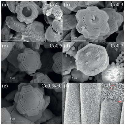
As shown in Fig. 2, the amount of urea had a great influence on the morphology of Co3O4. When the addition amount of urea was 0.1 g, Co3O4 showed 3D gear-shaped with an average size of 5.3 mm (Fig. 2a). With the increases of urea, the hollow structure of Co3O4 was gradually filled (Figs. 2b and c). When the amount of urea increased to 0.7 g, the Co3O4 showed a 3D-hexagonal morphology decorated with some nanoparticles (Fig. 2d). Morphologies had obvious influence on the surface area. As shown in Fig. S2 (Supporting information), all the samples exhibited an H3 type hysteresis loop, indicating mesoporous structure of samples. And the surface areas of Co0.1, Co0.3, Co0.5 and Co0.7 were 39.13, 46.32, 56.17 and 44.61 m2/g, respectively (Table S1 in Supporting information). The larger specific surface would provide more active sites in the catalytic reaction. Therefore, we chose Co0.5 for further modification. As shown in Fig. 2e, the morphology of Co0.5 had no obvious change after carbon modification, suggesting the calcination under nitrogen protection after soaking with glucose nearly had no effect on the morphology of the Co0.5. In addition, the as-prepared SnO2/CC had a uniform morphology, and the SnO2 nano-sheets were well grown on the carbon cloth with a thickness of 20 nm (Fig. 2f). This structure would provide more active sites for electrocatalytic reduction of CO2.
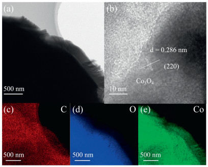
The transmission electron microscope (TEM) was used to certify the C was successful coated on the Co3O4. The TEM image of Co0.5@C showed that Co3O4 was wrapped by amorphous carbon (Figs. 3a and b). As shown in Figs. 3c-e, the element mapping of Co0.5@C also proved the Co3O4 was wrapped by C. And the results showed that the surface amorphous carbon still survived during the AOP in the Fig. S3 (Supporting information).
In addition, we further confirmed that Co3O4 was wrapped by amorphous carbon by X-ray photoelectron spectroscopy (XPS) and Raman. As shown in Fig. S4a (Supporting information), the XPS survey spectrum of Co0.5@C showed a distinct C 1s peak, which was consistent with the results of TEM and confirmed the presence of carbon. Furthermore, the Raman spectrum of Co0.5@C showed a broad G band at 1580 cm-1 (Fig. S4b in Supporting information), which confirmed the presence of amorphous carbon again [49]. Therefore, all the above results confirmed that the carbon was successfully wrapped on the Co0.5 surface.
Electrochemical impedance spectra (EIS) of the as-prepared Co3O4 and Co0.5@C electrodes showed that the semicircular diameter of Co0.5 was smaller than that of other Co3O4 electrodes (Fig. S5a in Supporting information), indicating the electron transport capacity of Co0.5 was higher than other Co3O4 electrodes. Compared with the Co0.5, the EIS semicircular diameter of Co0.5@C was further reduced, indicating that the electron transport capacity of Co0.5@C was better than the Co0.5 in the electrocatalytic process [50].
In order to better understand the performance of electro-catalytic reduction of CO2 on sheet-like SnO2/CC electrode, we analyzed the current density curve at different voltages by linear sweep voltammetry (LSV) under nitrogen and carbon dioxide (Fig. S5b in Supporting information). The change in current density was mainly derived from two parts: The current density produced by hydrogen evolution and CO2 reduction. As shown in Fig. S5b, the reduction current density of the sheet-like SnO2/CC in the CO2 atmosphere was significantly higher than that in the N2. This result indicated that SnO2 had high catalytic activity in the electro-catalytic reduction of CO2 and could effectively inhibit the precipitation of hydrogen [51]. The XPS spectrum of the O 1s and Sn 3d of SnO2/CC before and after reaction were shown in Fig. S5 [52-54]. As shown in Fig. S6a (Supporting information), the O 1s peaks, and the three sub-peaks at about 528.7 and 529.7 eV corresponded to the Sn-O-Sn and chemisorbed oxygen (OC), respectively. Fig. S6b (Supporting information) shows the two strong bands of Sn 3d5/2 and Sn 3d3/2 at about 486.9 and 495.4 eV indicated the formation of SnO2. And the comparison of XPS spectra before and after reaction showed that SnO2/CC had excellent stability.
Fig. 4a displayed the 4-NP degradation rate curves of different Co3O4 electrodes (Co0.1, Co0.3, Co0.5, Co0.7 and Co0.5@C), in which Co0.5/PMS showed the highest degradation ability, and its degradation efficiency was 74.5% in 60 min. This was related to the surface area and electron transport capacity of Co0.5. After coating C, the catalytic performance of Co0.5 was further improved, and the degradation efficiency of 4-NP was 85.1% in 60 min. Because of the abundant functional groups (hydroxyl groups and carboxyl groups) on the carbon surface, it would generate more CoOH+ that was more likely to activate PMS [55, 56].
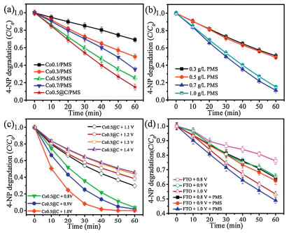
As shown in Fig. 4b, with the increase of PMS concentration, the degradation rate of 4-NP had significantly enhanced, and 0.7 g/L was the best. Because more sulfate radicals or hydroxyl radicals were generated during the reaction. However, when the concentration of PMS increased to 1.0 g/L, the catalytic degradation rate had slight decline, due to exceeding PMS would produce SO5·- instead of SO4·-, while SO5·- was less active than SO4·- [57, 58]. It had a shorter lifetime and worse degradation ability, which can be expressed by the following formulas (Eqs. 1–3).
|
|
(1) |
|
|
(2) |
|
|
(3) |
As shown in Fig. 4c, the degradation efficiency of Co0.5@C system was significantly influenced by bias voltages, and it was better than the AOPs or electrocatalytic oxidation, indicating that the electrocatalysis coupled with AOPs had advantages in the removal of organic pollutants. We designed a series of control experiments to study the synergistic relationship between electrocatalytic and AOPs. As shown in Fig. 4d, when different bias voltages were applied on the fluorine doped tin oxide (FTO), the 4-NP could be degraded and the removal efficiency of 4-NP at 0.8, 0.9 and 1.0 V were 23.9%, 34.5% and 46.6%, respectively. The results suggested the 4-NP could be directly degraded by electro-oxidation. Then, PMS was added during the electro-oxidation processes. As shown in Fig. 4d, the catalytic performance of FTO/PMS was significantly higher than single FTO, indicating that electrocatalysis coupled with AOPs could improve the degradation efficiency of 4-NP.
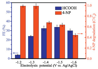
As shown in Fig. 5, 4-NP was degraded by electrocatalytic oxidation coupled with AOPs using Co0.5@C anode, and the electrocatalytic reduction of CO2 was realized through SnO2/CC cathode. When the voltage was 1.2 and 1.3 V, 4-NP could be completely degraded in 60 min. However, when the voltage was higher than 1.3 V, the catalytic degradation of 4-NP was obviously inhibited. According to the LSV results of SnO2/CC in CO2 atmosphere, the initial potential was about 1.0 V. As the voltage increased, the FE of CO2 reduction increased significantly. When the voltage was 1.5 V, the FE of formic acid reached a maximum value of 33.8% and the degradation efficiency of 4-NP reached 63.4%. Further increased the voltage, the FE had a slight decrease because the hydrogen evolution reaction competed with the reduction of CO2 [59]. The detailed results were shown in Table S2 (Supporting information). Therefore, 1.5 V was the optimal voltage value for the coupled system of 4-NP degradation and simultaneous CO2 reduction. And the total organic carbon (TOC) decreased rapidly from 5.913 mg/L to 1.483 mg/L in 60 min as shown in Fig. S7 (Supporting information), confirming that 74.9% of 4-NP can be mineralized to CO2 and H2O.
We used XPS characterization to explore the valence of Co elements. As shown in Fig. 6a, two peaks were located at 779.4 and 794.5 eV, which were related to Co 2p3/2 and Co 2p1/2 of Co3+ in Co3O4, respectively. In addition, the two peaks located at 780.6 and 795.9 eV belong to Co 2p3/2 and Co 2p1/2 of Co2+, respectively. According to XPS results, the contents of Co2+ and Co3+ in Co3O4 were estimated (Table S3 in Supporting information). The Co2+ played a crucial role in AOPs [46]. And the content of Co2+ in the Co0.5 was 66.8%, significantly higher than other Co3O4 electrodes. And the higher Co2+ content would produce more SO4·- for degradation of organic pollutants. The content of Co2+ was basically the same after carbon modification of Co0.5, which proved that carbon has no obvious influence on the valence state of cobalt. To further explore the differences in carbon-coated Co3O4 electrodes, we analyzed the XPS spectra of the O 1s of Co0.5 before and after carbon coating. As shown in Fig. 6b, the O 1s spectra of Co0.5 and Co0.5@C could be divided into three peaks centered at 533.0, 532.0 and 531.3 eV, corresponding to H-OH, C-OH and Co-OH, respectively. And the Co-OH content in the Co0.5@C was much higher than Co0.5 as shown in Fig. 6b, which improved the catalytic activity. It was because of Co-OH can combine with PMS to generate more SO4·- through H-bonding easily. Therefore, XPS confirmed that Co0.5@C had excellent catalytic performance.
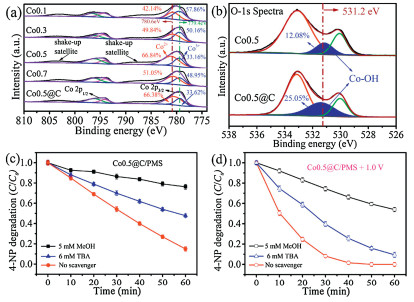
Tertbutyl alcohol (TBA) and methanol (MeOH) were used as the radical scavenger for OH and SO4·-, respectively. In the system of Co0.5@C/PMS, the degradation efficiency of 4-NP reduced from 75.1%–23.7% when the MeOH was added. With the addition of TBA, the degradation efficiency of 4-NP decreased from 75.1%–52.2%. Therefore, it can be concluded that SO4·- played more important role than OH. Similarly, in the system of Co0.5@C/PMS/1.0 V, the addition of MeOH resulted in the degradation efficiency reduced from 99.8%–45.1 %, while the addition of TBA made the degradation efficiency reduced from 99.8%–83.0% (Figs. 6c and d). Electron paramagnetic resonance (EPR) spectrum shown in Fig. S8 (Supporting information) also confirmed the presence of radicals. In summary, SO4·- and OH were the main active species in the electrocatalytic coupled with AOPs. This result was consistent with our previous studies [46]. And as shown in Fig. S9 (Supporting information), the sulfate radical quantification experiment also confirmed that with the increase of reaction time, the sulfate radicals in the system gradually increased, and the concentration reached 68.12 μmol/L in 60 min.
The synergetic mechanism of 4-NP degradation coupled with electrocatalytic CO2 reduction was proposed. In the part of anode, 4-NP was mineralized to CO2 by AOPs coupled with electrocatalytic oxidation based on SO4·- and OH over the Co3O4 electrode. Meanwhile, the oxidation of water produced a proton process that mainly occurred in the anode (Eq. 4). Then the generated H+ would move in the direction of the electric field and reached the cathode chamber through the cationic proton exchange membrane to participate in the CO2 reduction [60]. The CO2 reduction process could be as follows [61] (Eqs.5–7).
|
|
(4) |
|
|
(5) |
|
|
(6) |
|
|
(7) |
The CO2 reduction products were detected by NMR. As shown in Fig. S10a (Supporting information), the characteristic peaks of HCOOH were not observed under nitrogen conditions, whereas HCOOH was detected under CO2 atmosphere (Fig. S10b in Supporting information). Except for HCOOH, there was no peaks of other hydrocarbons, indicating that the SnO2/CC had high selectivity for the generation of HCOOH [62]. In order to better explain the formation mechanism of HCOOH on the SnO2/CC electrode, in situ FTIR spectro-electrochemical technique was used to detect the adsorbed species formed on the electrode surface. As shown in Fig. S11 (Supporting information), the absorption bands at 995, 1379, 1670 and 3288 cm-1 were attributed to the peak of C-O, -COO-, C=O and free O–H, respectively. It indicated the generation of HCOOH. Therefore, we proposed a possible CO2 reduction mechanism to understand the possible pathways for the reduction of CO2 to HCOOH as shown in Fig. S12 (Supporting information). First, the CO2 molecule captured an electron to form CO2 on the surface of the catalyst, and further reacted with HCO3 to form HCOO, then the HCOO combined with the proton and electron to form HCOOH (Eqs. 5–7).
Furthermore, the degradation route and the decomposition mechanism of 4-NP in the system of Co0.5@C/PMS at 1.3 V were well investigated. The concentration and composition of the reaction solution at different reaction time were tested by liquid chromatography-mass spectrometry (LC-MS). As shown in Fig. S13 (Supporting information), SO4·- and OH act as active species to attack some chemical bonds and then mineralize 4-NP to CO2 and H2O. Finally, a possible 4-NP degradation mineralization roadmap was put forward. The system also was used to degrade the landfill leachate as shown in Fig. S14 (Supporting information) and the results show that the system is also applicable to the treatment of actual wastewater.
In summary, a novel system of electrocatalysis coupled with AOPs and simultaneous CO2 reduction were constructed to degrade organic pollutants and simultaneously reduce CO2 to HCOOH using Co3O4@C anode and SnO2/CC cathode. In this process, the degradation efficiency of 4-NP can be markedly improved by the anode of Co3O4 modified by amorphous carbon, while the high FE and selectivity of CO2 reduction to HCOOH can be achieved via the SnO2/CC cathode. The promotion mechanism was proposed to explain the degradation of organic pollutants and reduction of CO2 into HCOOH in the process of electrocatalysis coupled with AOPs and simultaneous CO2 reduction. The present work provided an avenue for the coupling of electrocatalytic oxidation with AOPs and electrocatalytic reduction technology to treat organic pollutants with simultaneous resource cycling.
The authors declare that they have no known competing financial interests or personal relationships that could have appeared to influence the work reported in this paper.
We gratefully acknowledge the financial support of the National Natural Science Foundation of China (Nos. 51878325, 51868050, 51622806, 51378246 and 51720105001), the Natural Science Founda-tion of Jiangxi Province (Nos. 20162BCB22017, 20165BCB18008, 20171ACB20017, 20133ACB21001 and 06 20171BAB206049), and the Graduate Innovation Fund of Jiangxi Province (No. YC2018-S360).
Supplementary material related to this article can be found, in the online version, at doi:https://doi.org/10.1016/j.cclet.2020.01.017.
K.E. Trenberth, J.T. Fasullo, J. Kiehl, B. Am. Meteorol. Soc. 90(2009) 311-324. doi: 10.1175/2008BAMS2634.1
D. Tao, Y. Ning, Z. Yan, Greenh. Gases 7(2017) 1-19. doi: 10.1002/ghg.1625
M. Guo, X. Wang, Y. Liu, et al., Int. J. Remote Sens. 33(2012) 6838-6853. doi: 10.1080/01431161.2012.695094
S. Min, X. Tang, Y. Zhang, W. Li, Front. Ecol. Environ. 4(2006) 353-361. doi: 10.1890/1540-9295(2006)004[0353:CCICAA]2.0.CO;2
R.P. Schwarzenbach, T. Egli, T.B. Hofstetter, U.V. Gunten, B. Wehrli, Annu. Rev. Env. Resour. 35(2010) 109-136. doi: 10.1146/annurev-environ-100809-125342
Y. Chen, J.F. Li, P.Y. Liao, et al., Chin. Chem. Lett. (2019), doi: http://dx.doi.org/10.1016/j.cclet.2019.12.013.
D.W. Kolpin, E.T. Furlong, M.T. Meyer, et al., Environ. Sci. Technol. 36(2002) 1202-1211. doi: 10.1021/es011055j
R. Loos, R. Carvalho, D.C. António, et al., Water Res. 47(2013) 6475-6487. doi: 10.1016/j.watres.2013.08.024
S. Yi, G. Li, H. Hu, Z. Fang, W. Hua, Ind. Water Treat. 26(2006) 4-7. http://en.cnki.com.cn/Article_en/CJFDTotal-GYSC200603001.htm
S. Xie, S. Wu, S. Bao, Y. Wang, Z. Huang, Adv. Mater. 30(2018) 1800683. doi: 10.1002/adma.201800683
C. Zhu, F. Zhu, D.D. Dionysiou, et al., Water Res. 139(2018) 617.
Augugliaro, Vincenzo, Marta, et al., J. Photochem. Photobiol. C 7(2006) 127-144. doi: 10.1016/j.jphotochemrev.2006.12.001
F.Y. Saleh, G.F. Lee, H.W. Wolf, Water Res. 16(1982) 479-488. doi: 10.1016/0043-1354(82)90174-9
L. C, W. T, H. PC, et al., ACS Nano 13(2019) 6431. doi: 10.1021/acsnano.8b09301
J. Ji, Y. Peng, B. Wang, X. Li, Q. Zhang, Water Res. 170(2020) 115363. doi: 10.1016/j.watres.2019.115363
C. Ridruejo, F. Centellas, P.L. Cabot, I. Sires, E. Brillas, Water Res. 128(2018) 71-81. doi: 10.1016/j.watres.2017.10.048
Z. Yang, A. Yu, C. Shan, G. Gao, B. Pan, Water Res. 137(2018) 37-46. doi: 10.1016/j.watres.2018.03.006
S. Hu, J. Hu, B. Liu, et al., Water Res. 145(2018) 162-171. doi: 10.1016/j.watres.2018.08.027
G.H. Zhao, R. Chen, T.Y. Gao, et al., Res. Environ. Sci. 16(2003) 51-54.
H. Wang, B. Bakheet, S. Yuan, et al., J. Hazard. Mater. 294(2015) 90-98. doi: 10.1016/j.jhazmat.2015.03.058
I. Addition, Environ. Sci. Technol. 2012(2012) 3.
F. Deng, O. Garcia-Rodriguez, H. Olvera-Vargas, et al., Electrochim. Acta 272(2018) 176-183. doi: 10.1016/j.electacta.2018.03.160
K. Kim, S. Cotty, J. Elbert, et al., Adv. Mater. (2019) 1906877.
Z. Shen, Y. Zhang, C. Zhou, et al., Water Res. 170(2019) 115357. https://www.sciencedirect.com/science/article/abs/pii/S0043135412005192
S.B. Hammouda, F. Zhao, Z. Safaei, et al., Appl. Catal. B:Environ. 233(2018) 99-111. doi: 10.1016/j.apcatb.2018.03.088
L.W. Matzek, M.J. Tipton, A.T. Farmer, A.D. Steen, K.E. Carter, Environ. Sci. Technol. 52(2018) 5875-5883. doi: 10.1021/acs.est.8b00015
J.L. Wang, L.J. Xu, Crit. Rev. Environ. Sci. Technol. 42(2012) 251-325. doi: 10.1080/10643389.2010.507698
T. Zhang, H. Zhu, J.P. Croue, Environ. Sci. Technol. 47(2013) 2784-2791. doi: 10.1021/es304721g
J. Rosen, G.S. Hutchings, F. Jiao, J. Catal. 310(2014) 2-9. doi: 10.1016/j.jcat.2013.05.003
S.B. Hammouda, F. Zhao, Z. Safaei, et al., Appl. Catal. B:Environ. 215(2017) 60-73. doi: 10.1016/j.apcatb.2017.05.051
R.R. Solís, F.J. Rivas, O. Gimeno, Appl. Catal. B:Environ. 200(2017) 83-92. doi: 10.1016/j.apcatb.2016.06.058
Pradeep Shukla, H. Sun, et al., Sep. Purif. Technol. 77(2011) 230-236. doi: 10.1016/j.seppur.2010.12.011
X.T. Wang, T. Ouyang, L. Wang, et al., Angew. Chem. Int. Ed. 58(2019) 13291-13296. doi: 10.1002/anie.201907595
M. Ahmad, A.L. Teel, R.J. Watts, J. Contam. Hydrol. 115(2010) 34-45. doi: 10.1016/j.jconhyd.2010.04.002
A. Khan, H. Wang, L. Yong, et al., J. Mater. Chem. A 6(2017) 1590-1600.
G.X. Huang, C.Y. Wang, C.W. Yang, P.C. Guo, H.Q. Yu, Environ. Sci. Technol. 51(2017) 12611-12618. doi: 10.1021/acs.est.7b03007
J. Yan, W. Gao, M. Dong, et al., Chem. Eng. J. 295(2016) 309-316. doi: 10.1016/j.cej.2016.01.085
X. Zhang, M. Feng, R. Qu, et al., Chem. Eng. J. 301(2016) 1-11. doi: 10.1016/j.cej.2016.04.096
L. Rizzo, S. Meric, M. Guida, D. Kassinos, V. Belgiorno, Water Res. 43(2009) 4070-4078. doi: 10.1016/j.watres.2009.06.046
A. Babuponnusami, K. Muthukumar, J. Environ. Chem. Eng. 2(2014) 557-572. doi: 10.1016/j.jece.2013.10.011
N.F. Moreira, C.A. Orge, A.R. Ribeiro, et al., Water Res. 87(2015) 87-96. doi: 10.1016/j.watres.2015.08.059
R. Martinez-Haya, C. Sabater, M.Á. Castillo, M.A. Miranda, M.L. Marin, J. Hazard. Mater. 351(2018) 277-284. doi: 10.1016/j.jhazmat.2018.03.010
P. Aravind, H. Selvaraj, S. Ferro, G.M. Neelavannan, M. Sundaram, J. Clean. Prod. 182(2018) 246-258. doi: 10.1016/j.jclepro.2018.02.064
J.P. Zou, D.D. Wu, J.M. Luo, et al., ACS Catal. 6(2016) 6861-6867. doi: 10.1021/acscatal.6b01729
W.H. Dong, D.D. Wu, J.M. Luo, et al., J. Catal. 349(2017) 218-225. doi: 10.1016/j.jcat.2017.02.004
J.P. Zou, Y. Chen, S.S. Liu, et al., Water Res. 150(2019) 330-339. doi: 10.1016/j.watres.2018.11.077
W.D. Oh, Z. Dong, G. Ronn, T.T. Lim, J. Hazard. Mater. 325(2017) 71-81. doi: 10.1016/j.jhazmat.2016.11.056
H.W. Kim, H.G. Na, Y.J. Kwon, et al., ACS Appl. Mater. Interfaces 9(2017) 31667-31682. doi: 10.1021/acsami.7b02533
A. Jorio, A.G.S. Filho, Annu. Rev. Mater. Res. 46(2016) 357-382. doi: 10.1146/annurev-matsci-070115-032140
M. Asadi, K. Kim, C. Liu, et al., Science 353(2016) 467-470. doi: 10.1126/science.aaf4767
Y. Liu, M. Fan, Z. Xia, et al., Electrochim. Acta 248(2017) 123-132. doi: 10.1016/j.electacta.2017.07.140
J. Zheng, L. Zhang, et al., Appl. Catal. B:Environ. 231(2018) 34-42. doi: 10.1016/j.apcatb.2018.02.061
L. Zhang, J. Shi, Y. Huang, et al., ACS Appl. Mater. Interfaces 11(2019) 12958-12967. doi: 10.1021/acsami.8b22533
B. Kumar, V. Atla, J.P. Brian, et al., Angew. Chem. Int. Ed. 56(2017) 3645-3649. doi: 10.1002/anie.201612194
P. Shi, S.U. Ruijing, F. Wan, et al., Appl. Catal. B:Environ. 123-124(2012) 265-272.
X. Chen, J. Chen, X. Qiao, D. Wang, X. Cai, Appl. Catal. B:Environ. 80(2008) 116-121. doi: 10.1016/j.apcatb.2007.11.009
X. Lin, Y. Ma, J. Wan, W. Yan, Chem. Eng. J. 315(2017) 304-314. doi: 10.1016/j.cej.2017.01.036
C. Gong, F. Chen, Q. Yang, et al., Chem. Eng. J. 321(2017) 222-232. doi: 10.1016/j.cej.2017.03.117
Z. Xia, L. Tao, Y. Liu, J. Qiao, Appl. Catal. B:Environ. 218(2017) 46-50. doi: 10.1016/j.apcatb.2017.06.032
X. Sun, Q. Zhu, X. Kang, et al., Angew. Chem. Int. Ed. 50(2011) 6771-6775. doi: 10.1002/anie.201102759
A. Klinkova, P.D. Luna, C.T. Dinh, et al., ACS Catal. 6(2016) 8115-8120. doi: 10.1021/acscatal.6b01719
C.E. Moore, E.L. Gyenge, ChemSusChem 10(2017) 3512-3519. doi: 10.1002/cssc.201700761

Figure 2 SEM of Co0.1 (a), Co0.3 (b), Co0.5 (c), Co0.7 (d), Co0.5@C (e) anodes and SnO2/CC electrode (f).

Figure 4 4-NP degradation in the Co3O4/PMS system with different anodes (a), in the Co0.5/PMS system with different concentrations of PMS (b), in the Co0.5@C system with different voltages (c), and in the FTO and FTO/PMS systems with different voltages (d).

Figure 6 XPS spectra of the Co 2p of the as-prepared Co3O4 electrodes (a) the O 1s of the electrode before and after carbon coating of Co0.5 (b); And removal efficiency of 4-NP with the addition of scavengers in different reaction systems: Co0.5@C/PMS (solid) (c) and Co0.5/PMS at 1.0 V bias potential (hollow) (d). Test condition: [electrolyte] = 0.1 mol/L Na2SO4·-, [4-NP] =10 mg/L, [PMS] = 0.5 g/L; T = 25 C. mM: mmol/L.

 扫一扫看文章

扫一扫关注我们
 DownLoad:


 下载:
下载:

