 Figure 1.
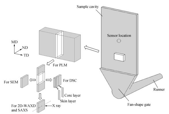
Schematic diagram of specimen preparation for tests: MD, the molding direction (i.e., flow direction); TD, the transverse direction; ND, the direction normal to the MD-TD plane (i.e., thickness direction)
Figure 1.
Schematic diagram of specimen preparation for tests: MD, the molding direction (i.e., flow direction); TD, the transverse direction; ND, the direction normal to the MD-TD plane (i.e., thickness direction)
Citation:
Zhi-hao Zhao, Fei-fei Wang, Man Zhou, Kai-zhi Shen, Jie Zhang. Altering the Hierarchical Morphology Distribution of Injection Molded Polyethylene by the Introduction of Crosslink Network and Periodical Shear[J]. Chinese Journal of Polymer Science,
2016, 34(12): 1479-1489.
doi:
10.1007/s10118-016-1865-6

Altering the Hierarchical Morphology Distribution of Injection Molded Polyethylene by the Introduction of Crosslink Network and Periodical Shear
English
Altering the Hierarchical Morphology Distribution of Injection Molded Polyethylene by the Introduction of Crosslink Network and Periodical Shear
Abstract:
High density polyethylene (HDPE) with moderate content of crosslink network (CPE) was successfully prepared through chemical method. Specimens for structural characterization have been molded by conventional injection molding (CIM) and pressure vibration injection molding (PVIM). Influence of crosslink network on hierarchical morphology distribution and mechanical properties was systematically studied. Polarized light microscopy (PLM) revealed that both CIM and PVIM PE samples have a typical "skin-core" structure and the thickness of shear layer of CIM PE and PVIM CPE samples obviously increase. Scanning electron microscopy (SEM) showed that shish-kebab structures are clearly observed in shear layer of CIM CPE sample, indicating that the crosslink network can surely improve the formation of shish-kebab structures. Moreover, we suppose that shish-kebab structures emerged in shear and core layer of PVIM CPE sample. Wide-angle X-ray diffraction (WAXD) and small-angle X-ray scattering (SAXS) confirmed that more orientation and shish-kebab structures form even in core layer of PVIM CPE sample, which demonstrated that the hierarchical morphology was apparently altered by periodical shear and crosslink network. Finally, the mechanical properties revealed that this oriented structure increase the tensile strength from 31 MPa of CIM PE sample to 46 MPa of PVIM CPE sample. However, the tensile behavior tended to change from ductile fracture to brittle fracture.
-
Key words:
- Shish-kebab
- / Morphology distribution
- / Periodical shear
- / Mechanical properties
-
INTRODUCTION
It is well accepted that the properties of polymeric materials are mainly dominated by the crystalline morphology[1]. Naturally, it is necessary to investigate the property-morphology interrelationships in practical polymer processing. Flow-induced crystallization of semi-crystalline polymers has been a vital researched subject for the past few decades since many polymer processing operations, such as extrusion, injection molding, fiber spinning and film blowing, etc., could be accompanied by complex exterior fields which usually influence orientation of molecular chains, crystallization kinetics and final crystal morphology[2-8]. Hence, different crystalline morphologies (spherulites, cylindrites, shish-kebab, and fibrous crystal) can be obtained with the variant of processing condition.
Injection molding with high production efficiency is a very popular processing method in polymeric processing industry. Owing to the coexistence of complex temperature and shear gradient, a typical “skin-core” structure forms in the thickness direction of molded parts[9, 10]. The skin-core structure consists of a thin skin layer and a thick core layer; between these two layers is a shear layer. It is understandable that skin layer and shear layer are subjected to strong shear force and fast melt cooling rate, resulting in some oriented structures formed in this two layers. Whereas, for the core layer, the chain orientation degree is low and only spherulites can be generated. Many researchers have demonstrated that oriented structures in this two layers have a dominated influence on mechanical properties of articles[11, 12].
Increasing the thickness of oriented layer and altering its composing structures are usually helpful to improve mechanical properties of products. However, for CIM parts, the thickness of oriented layer is narrow, and thus the oriented structure content is not enough to meet the practical needs. Fortunately, many investigations have been conducted on how to increase the thicknesses of oriented layer for improving mechanical properties of products. It is noteworthy that stronger shear force can induces higher chain orientation and fast melt cooling rate is beneficial to retain chain orientation via suppressing chain relaxation. According to this principle, many new processing technologies were developed in the past, such as oscillation shear injection molding such (OSIM)[13-15], gas-assisted injection molding (GAIM)[16-18], periodical vibration injection molding (PVIM)[19-22] etc., which could efficiently introduce special exterior shear field on molecular chains during filing and packing stages. Eventually, more oriented structures could be retained in products. However, the chain orientation degree of core layer in parts remains low, because the stretched chains are easy to relax at high temperature and slow melt cooling rate on account of the unstable physical entanglement points between molecular chains which can easily slip and change its position to return original unoriented state. Undoubtedly, if some stable entanglement point like cross-linking point can be introduced between molecular chains, the relaxation time of chain would be greatly prolonged. Yang et al.[15] prepared lightly cross-linked HDPE pellets through electron radiation, and successfully fabricated samples with large contents of shish-kebab structures processing with OSIM technology. He found that OSIM processed specimens with cross-linked chain network were composed of interlinked shish-kebab structures even in the core layer, resulting in the increment of tensile strength and tensile modulus. Besides, some researchers reported that addition of supermolecular polymers with long relaxation time could also maintain oriented structures[2, 23-26]. These polymers, such as ultra-high molecular weight polyethylene (UHMWPE) and crosslink network, need longer time to disorient once they have been oriented. Because these oriented supermoleculars were entangled with short chains of matrix, the relaxation process of oriented short chains also slowed down. For example, Zhang et al.[25] used UHMWPE as the orientation-maintained phase, and fabricated standard samples with oriented structures by Mini-Jet injection molding.
In the present work, a small amount of cross-linking agent was added to introduce moderate content of crosslink network in neat HDPE. It is expected that more stable entanglement points or some permanent cross-linking points (the orientation-maintained phase) would be generated in this cross-linking network. Furthermore, to facilitate stretching of molecular chains, the PVIM technology was used to exert strong periodical shear stress on melt during filing and packing stages. For comparison, samples with and without cross-linking network were also fabricated by CIM. The influence of crosslink network on hierarchical morphology and mechanical properties was systematically studied. This work may provide a feasible method for enhancing mechanical properties. Meanwhile, a better understanding for morphology-performance interrelationship could be built.
EXPERIMENTAL
Mechanical Tests
An RGT-10 computer control electronic universal testing was used to evaluate the tensile properties under a crosshead speed of 50 mm/min at room temperature according to ASTM-D 638. The dumbbell samples for the test were cut along the flow direction from the injection molded thin plates. Five samples were used for each measurement, and the reported data represented an average value.
Polarized Optical Microscopy (PLM)
A polarization light microscope, DX-1, produced by Jiang-Xi Phoenix Optical Corporation, was used to observe the microstructure of sample. The photographs were recorded by a Nikon 500D camera. The specimen preparation for tests was shown in Fig. 1.
Figure 1.
Schematic diagram of specimen preparation for tests: MD, the molding direction (i.e., flow direction); TD, the transverse direction; ND, the direction normal to the MD-TD plane (i.e., thickness direction)
Sample Preparation
The crosslinking PE particles were prepared by melt mixing with 0.1 wt% DCP in a Haake mixer at 45 r/min, 180 ℃ for 6 min. After being pelletized, the pellets were injection molded into thin plate by utilizing the PVIM technique, the details of which was described in our previous works[19-22]. The processing temperature profile was limited within 170−200 ℃ from hopper to nozzle, and the mold temperature was 40 ℃. The injection pressure, vibration pressure, and vibration frequency were set as 35 MPa, 50 MPa, and 1 Hz, respectively. For dynamic rheology tests, the pellets were compression molded into specific disks (1.2 mm thick with a diameter of 25 mm) at 200 ℃.
Synchrotron Two-dimensional Wide-angle X-ray Diffraction (2D-WAXD) and Small-angle X-ray Scattering (SAXS)
The synchrotron 2D-WAXD and SAXS experiments were performed on BL16B1 beamline of Shanghai Synchrotron Radiation Facility (SSRF) with a Mar CCD (Mar165, Rayonix L.L.C., USA). The wavelength of X-ray, λ, was 0.124 nm. Sample-detector distance was set at 137 and 5127 mm in the direction of the beam for WAXD and SAXS data collections, respectively. The incident X-ray beam was set perpendicular to the flow direction. During tests, the X-ray beam would move in the thickness direction, so that four positions, which were corresponding to skin to core layers, would be set for collecting WAXD and SAXS signals. To evaluate the molecular orientation, the orientation parameter was calculated mathematically using Picken’s method from the (110) reflection of WAXD for PE[27]. Orientation parameter F=1 means that polymer chains orient along the flow direction completely; F=-0.5 means that polymer chains orient vertical to the flow direction completely; F=0 means that polymer chains are random oriented.
Scanning Electron Microscopy (SEM)
SEM observation was conducted by SEM instrument (model JSM-5900 LV) operating at 20 kV. The specimens were ultra-micro cut, and then the surface was etched in a mixture of potassium permanganate, sulphuric acid, and nitric acid. Before observation, the etched surface was coated with a thin layer of gold.
Dynamic Rheological Measurement
Dynamic rheology property was conducted using a rotational rheometer (Malvern Instruments, Bohlin Gemini 200). Steady shear mode was performed at the shear rate of 0.001-100 s-1 at 190 ℃, and the shear strain was set at 2%.
Material
High density polyethylene (HDPE 2911), purchased from Fushun Petroleum Chemical Co., China, has a melt flow rate (MFR) of 20 g/10min (190 ℃, 2.16 kg), Mw=6 × 10⁴g/mol, and Mw/Mn=3.3, where Mw and Mn are the weight-average molecular weight and the number-average molecular weight, respectively. Cross-linking agent, dicumyl peroxide (DCP), was supplied by West Reagent.
RESULTS AND DISCUSSION
Phase Morphology
To obtain more information on the morphology-property relationship, PLM and SEM experiments were conducted. Under a certain observation angle, the skin-core structure can be observed based on different polarization properties, as shown in Fig. 5. Figures 5(a) and 5(b) show that PE samples clearly exhibit a typical skin-core structure. Comparatively, CIMPE sample consists of a very thin shear layer and a thick core layer, while PVIM PE sample has thicker shear layer and thinner core layer. HDPE used in this study that has small molecular weight and short molecular chains is very easy to relax and disorient once molecular chains oriented, which contributes to a thin shear layer during CIM process. However, periodical shear provided by PVIM process can promote more oriented structures and slow down the disorientation process, and thus results in a thicker shear layer. Figures 5(c) and 5(d) show that the skin-core structures of CPE samples molded by PVIM become undistinguished, whereas the thickness of shear layers greatly increases. Moreover, the spherulite structure of CPE samples was destroyed and cannot be identified clearly via PLM. In general, it is certain that CPE samples possess high orientation degree, which could be supported by WAXD and SAXS.
 Figure 5.
PLM observations of samples for (a) CIM PE, (b) PVIM PE, (c) CIM CPE and (d) PVIM CPE
Figure 5.
PLM observations of samples for (a) CIM PE, (b) PVIM PE, (c) CIM CPE and (d) PVIM CPE
Figure 6 displays the SEM images of PE samples. The crystalline morphology of core layer of CIM PE sample is large banded spherulites (Fig. 6(b1)), which is caused by synergistically twisting of lamellae expressed in WAXD. With the introduction of periodical shear, the size of spherulites in core layer decreases and lamellae twisting behavior weakens as shown in Fig. 6(b2). This is because the periodical shear influenced the crystallization process, and thus made growth environment for spherulites worse. Meanwhile, crystalline morphology of shear layer is the typical shish-kebab structure as presented in Fig. 6(a2).
 Figure 6.
SEM images of etched PE samples
Figure 6.
SEM images of etched PE samples
Figure 7 represents the SEM pictures of CPE samples. The crystalline morphologies of CPE samples are quite different from those of PE samples. Many shish-kebab structures are clearly observed in shear layer of CIM CPE sample (Fig. 7(a1) and 7(b1)) compared with CIM PE sample (Fig. 6(a1)), which indicates that the crosslink network can surely improve the formation of shish-kebab structures. Moreover, the crystalline morphology in core layer of CIM CPE sample is randomly oriented lamellae (Fig. 7(c1)), which is consistent with the SAXS patterns of core layer of CIM PE sample (Fig. 4c). Figures 7(b2) and Figures 7(c2) depict nearly similar crystalline morphologies. According to information provided by WAXD and SAXS patterns of PVIM CPE sample, we suppose it is shish-kebab structures that emerged in shear layer and core layer of PVIM CPE sample. However, the crystalline structures in core layer are looser than shear layer for PVIM CPE sample, and do not perfectly orient along the flow direction.
 Figure 7.
SEM images of etched CPE samples
Figure 7.
SEM images of etched CPE samples
Orientation Analysis
Figure 3 represents the selected 2D-WAXD patterns of samples from different layers, viz. surface, intermediate (locations of 200, and 500 μm away from surface) and core layer. For all WAXD patterns, two clear crystal reflections from the inner to outer areas, which are indexed as (110) and (200) crystal planes of PE, are observed. Figure 3(a) shows that the reflections of skin layer are anisotropic with four (110) arcs in the off-axis direction and two (200) arcs in the meridian direction, which confirms the presence of twisted lamellae[4, 28, 29].However, only two isotropic reflections are found in the rest layers of CIM PE sample, indicating that there is no preferred crystal orientation. Figure 3(b) displays the WAXD patterns of PVIM PE sample where the arc-like reflections are observed except for in core layer, which implies that the orientation structures increase a little compared with CIM PE sample. Notably, the WAXD patterns of CIM and PVIM CPE samples exhibit two arc-like (110) reflections in the equator direction and two (200) reflections in the sloping direction of meridian, indicating a very strong crystal orientation, as shown in Figs. 3(c) and 3(d). The reason will be discussed in the succeeding section.
 Figure 3.
2D-WAXD patterns of (a) CIM PE, (b) PVIM PE, (c) CIM CPE and (d) PVIM CPE The numbers at top of the patterns indicate the positions away from surface of specimens.
Figure 3.
2D-WAXD patterns of (a) CIM PE, (b) PVIM PE, (c) CIM CPE and (d) PVIM CPE The numbers at top of the patterns indicate the positions away from surface of specimens.
The orientation parameters F of samples were estimated according to the intensity of (110) plane along azimuthal angle and summarized in Table 1. Because there is no appropriate method to calculate orientation parameters of twisted lamellae, the orientation parameters of surface for PE samples are absent. For PVIM samples, the orientation parameters are higher than those of CIM samples in the corresponding regions, which can be understood that periodical shear prompts the orientation of molecular chains and thus generates more oriented crystalline structures. In addition, the orientation degrees of CPE samples are higher than those of PE samples, and don’t considerably decrease from skin to core layer. One can also observe that the orientation degree of sub-skin layer is the highest, and decreases continuously from sub-skin layer to core layer for CPE samples.
 Table 1.
Orientation parameter of samples calculated from the azimuth diffraction curves of the (110) plane
Table 1.
Orientation parameter of samples calculated from the azimuth diffraction curves of the (110) plane
Sample Positions (distance away from surface, μm) Surface 200 500 1000 CIM PE - 0.35 0 0 PVIM PE - 0.48 0.11 0 CIM CPE 0.81 0.85 0.74 0.58 PVIM CPE 0.81 0.88 0.82 0.62 “-” means cannot be calculated. Table 1. Orientation parameter of samples calculated from the azimuth diffraction curves of the (110) planeFurther studies were conducted via 2D-SAXS, and Fig. 4 presents the selected 2D-SAXS patterns of various samples in different layers. Figures 4(a) and 4(b) show that the SAXS patterns of core layers of PE samples exhibit a diffuse ring that means no considerable orientation, whereas the patterns of skin and intermediate layers present a pair of intense meridional scattering peaks with equatorial streak indicating relatively high crystal orientation degree. Generally, the meridional scattering maxima is attributed to kebab lamellas that are perpendicular to the flow direction, while the equatorial streak is owing to the formation of shish structure with extended-chains parallel to the flow direction. Figures 4(c) and 4(d) show that the SAXS patterns of skin and intermediate layers also exhibit two meridional scattering peeks and equatorial streaks. However, streaks of shish disappear, and only signal of oriented kebab lamellae is presented in core layers of CPE samples. This interesting phenomenon will be discussed later.
 Figure 4.
2D-SAXD patterns of (a) CIM PE, (b) PVIM PE, (c) CIM CPE and (d) PVIM CPE The numbers at top of the patterns indicate the positions away from surface of specimens.
Figure 4.
2D-SAXD patterns of (a) CIM PE, (b) PVIM PE, (c) CIM CPE and (d) PVIM CPE The numbers at top of the patterns indicate the positions away from surface of specimens.
Mechanical Properties
Since different crystalline structures have been generated, it is interesting to know what difference may cause in mechanical properties. Figure 8(a) presents the loading-displacement curves of all samples. PE samples reveal normal ductile behavior caused by the loose packing patterns of oriented structures. However, CPE samples exhibit brittle fracture behavior. This is because that high contents of shish-kebab structures could change the tensile behavior of parts from ductile to brittle fracture, which was reported in other studies[15]. Figure 8(b) shows the tensile strength of PE and CPE samples. The tensile strength of CIM PE sample is 30 MPa, whereas it is considerably enhanced to 37 MPa after the introduction of periodical shear. Generally, the skin layer of molded samples is very thin, and thus its influence on mechanical properties is very slight compared with other two layers and can be ignored. In addition, the SEM and PLM results revealed that more oriented structures formed in shear layer and the thickness of shear layer increased under periodical shear condition. Therefore, this enhancement should be attributed to the transition of crystalline structure in intermediate region from isotropic spherulites to oriented structures. As for CIM and PVIM CPE samples, the tensile strength is remarkably enhanced to 40 and 46 MPa, which were nearly 1.3 and 1.5 times that of CIM PE sample, respectively. CIM CPE sample has higher tensile strength even than that of PVIM PE sample, which may be owing to the strengthened entanglement between lamellas caused by crosslink network and change of crystalline morphology. It directly demonstrates that crosslink network plays an important role in improving mechanical properties. Furthermore, the contents of oriented structures with high strength and strong entanglement increase under periodical shear, resulting in the further enhancement of CPE samples.
 Figure 8.
Tensile properties of samples: (a) loading-displacement curves; (b) tensile strength
Figure 8.
Tensile properties of samples: (a) loading-displacement curves; (b) tensile strength
Dynamic Rheological Property
Figure 2 shows the dynamic rheological properties of PE and CPE. Both materials exhibit obvious shear thinning (non-Newtonian) behavior in the whole shear rate range. CPE possesses the same complex viscosity with neat PE in high-frequency shear condition, but higher value in low-frequency shear range, which indicates that crosslink network surely improved the complex viscosity. Generally, crosslink network decreases the free volume of PE molecule chains, which weakens the mobility of molecular chains and increases the relaxation time for oriented chains. Thus, it can be concluded that moderate content of crosslink network was certainly initiated by DCP.
 Figure 2.
Dynamic rheology properties of neat PE and CPE samples
Figure 2.
Dynamic rheology properties of neat PE and CPE samples
Discussion
It is well known that the final crystalline morphology essentially stems from different flow-induced morphologies of nuclei. The formation of nuclei is strongly influenced both by the nature of molecular chains and adjusting processing conditions. Periodical shear can induce the orientation of molecular chains and thus generate more oriented crystalline structures. The SAXS patterns and SEM images expressed that typical shish-kebab structures were observed in shear layer of PVIM CPE sample, indicating that the crosslink network could improve the formation of oriented structures. Therefore, periodical shear can promote the initial formation of oriented nuclei, and so did crosslink network, which contributed to more oriented crystalline structures.
The shear and core layer of PVIM CPE sample exhibited nearly similar crystalline morphology; however, the only difference is whether crystalline structures possess shish structures. The SAXS patterns of PVIM CPE sample revealed that the shear layer presented typical reflections of shish-kebab, namely, two-dot reflections of kebab in meridian direction and intense streak of shish in equator direction, whereas the shish signal in core layer was absent, and the kebab signal solely existed. This interesting finding raises our attention and is thought to be worth further research. Currently, the formation mechanism of shish-kebab followed the concept of “coil-stretch” transition first proposed by Keller et al[6, 30, 31]. Since no signal of shish was found, did it mean that shish did not form? We presumed that content of shish in core layer is probably too small to detect by SAXS, or that extended chains used to form the shish lamellae are just a few short oriented segments.Furthermore, crosslink network could participate in the formation of shish according to some literatures[15, 33], and could increase amounts of extended chains and maintain oriented molecular chains, which promotes formation of more shish. However, crosslink network destroys the regularity of molecular chains, and certainly decreases the length of extended chains, which induced smaller shish lamellae. Therefore, the decreases in amount and size of shish lamellae are two main factors for the difficulty to detect shish signal through SAXS. In the present study, addition of crosslink network undoubtedly influenced the formation of shish-kebabs, and thus changed hierarchical morphology distribution.
Transition from ductile fracture to brittle fracture behavior is detailedly contributed to the competing effects: (i) The mechanism of fracture behavior of materials[33-35] may result in the transition. When semi-crystalline polymers are suffering tensile stress, the amorphous phase first yields, and then yielding of crystal phase occurs until the deformation of amorphous phase is big enough. However, the physical entanglement of molecular chains in amorphous phase is enhanced permanently and strongly after crosslinking. Those physical and chemical entanglement points would confine the deformation of amorphous phase to a certain degree. (ii) Crosslink network leads to the worse regularity of molecular chains, which certainly affects crystallization process of molecular chains and finally induces crystals with thinner lamellae and more drawbacks. Those imperfect crystals usually act as stress concentration points, and thus contribute to brittle fracture behavior. (iii) Crystalline morphology plays an important role in the change of tensile behavior. SEM results showed crystalline morphologies of samples are almost oriented structures with brittle behavior, as shown in Fig. 7. Therefore, it is presumed that crystals deform in a way of lamellae sliding after yielding of amorphous phase; whereas, it is very difficult for oriented shish-kebab structures to realize the process. The observed change in tensile behavior is primarily due to the existence of a large amount of shish-kebabs in shear and core layers. In a word, the deformation of crystalline phase is apparently restricted after introduction of crosslink network.
CONCLUSIONS
Research on crosslink network and periodical shear altering morphology distribution of injection molded PE samples was conducted. PLM, SEM, 2D-WAXD and SAXS were used to determine the interrelationships between morphology and properties. Crosslink network efficiently maintains the oriented structures forming infilling process. Meanwhile, periodical shear would be able to increase the thickness of shear layer, and thus somehow eliminated the skin-core effect and altered the hierarchical morphology distribution. Crystalline morphologies in shear and core layer of PVIM CPE sample are oriented crystalline structures which led to an over 50% increment in tensile strength. An interesting result is the finding of oriented shish-kebabs with no shish signal in SAXS patterns. The decrease in amounts and size of shish lamellae in core layer might be dominating factors for the difficulty to detect shish signal through SAXS. In present work, a feasible method was obtained to enhance the mechanical properties of injection molded PE parts, and also adopted to provide some inspiration for practical processing of PE such as pipe extrusion.
-
-
[1]
Sedighiamiri, A., Govaert, L.E., Kanters, M.J.W. and van Dommelen, J.A.W., J. Polym. Sci., Part B:Polym. Phys., 2012, 50(24):1664 doi: 10.1002/polb.23136
-
[2]
Dikovsky, D., Marom, G., Avila-Orta, C.A., Somani, R.H. and Hsiao, B.S., Polymer, 2005, 46(9):3096 doi: 10.1016/j.polymer.2005.01.086
-
[3]
Hsiao, B.S., Yang, L., Somani, R.H., Avila-Orta, C.A. and Zhu, L., Phys. Rev. Lett., 2005, 94(11):117802 doi: 10.1103/PhysRevLett.94.117802
-
[4]
Kolnaar, H.W. and Keller, A., Polymer, 1997, 38(8):1817 doi: 10.1016/S0032-3861(96)00707-0
-
[5]
Nadkarni, V.M. and Schultz, J., J. Polym. Sci., Part B:Polym. Phys., 1977, 15(2):2151
-
[6]
Somani, R.H., Yang, L.; Zhu, L. and Hsiao, B.S., Polymer, 2005, 46(20):8587 doi: 10.1016/j.polymer.2005.06.034
-
[7]
Yang, L., Somani, R.H., Sics, I., Hsiao, B.S., Kolb, R., Fruitwala, H. and Ong, C., Macromolecules, 2004, 37(13):4845 doi: 10.1021/ma049925f
-
[8]
Dukovski, I. and Muthukumar, M., J. Chem. Phys., 2003, 118(14):6648 doi: 10.1063/1.1557473
-
[9]
Fujiyama, M., Wakino, T. and Kawasaki, Y., J. Appl. Polym. Sci., 1988, 35(1):29 doi: 10.1002/app.1988.070350104
-
[10]
Fujiyama, M. and Wakino, T., J. Appl. Polym. Sci., 1991, 43(1):57 doi: 10.1002/app.1991.070430108
-
[11]
Schrauwen, B.A.G., Breemen, L.C.A.V., Spoelstra, A.B., Govaert, L.E., Peters, G.W.M. and Meijer, H.E.H., Macromolecules, 2004, 37(23):8618 doi: 10.1021/ma048884k
-
[12]
Kech, A., Ludwig, H.C., Möginger, B., Eyerer, P. and Christianse, D.C., Int. Polym. Proc., 2000, 15(2):202 doi: 10.3139/217.1588
-
[13]
Zhang, Z., Zhang, R., Huang, Y., Lei, J., Chen, Y.H., Tang, J.H. and Li, Z.M., Ind. Eng. Chem. Res., 2014, 53(24):10144 doi: 10.1021/ie5012867
-
[14]
Zhong, G.J., Chen, Z.C., Li, Z.M., Shen, K.Z., Li, L. and Hsiao, B.S., J. Macromol. Sci., Part B:Phys., 2010, 50(2):383
-
[15]
Yang, H.R., Lei, J., Li, L., Fu, Q. and Li, Z.M., Macromolecules, 2012, 45(16):6600 doi: 10.1021/ma300974w
-
[16]
Zhang, Q.P., Wang, L., Xia, X.C., Feng, J.M., Fu, X.R. and Yang, M.B., J. Appl. Polym. Sci., 2014, 131(11):2928
-
[17]
Hu, S., Yang, W., Liang, S.P., Yang, B. and Yang, M.B., Macromol. Sci., B., 2009, 48(6):1201 doi: 10.1080/00222340903039313
-
[18]
Yang, B., Fu, X.R., Yang, W., Liang, S.P., Sun, N., Hu, S. and Yang, M.B., Macromol. Mater. Eng., 2009, 294(5):336 doi: 10.1002/mame.v294:5
-
[19]
Zhang, J., Liu, H., Zhang, L., Zhou, Q., Gao, X. and Shen, K., Polym. Bull., 2012, 68(1):239 doi: 10.1007/s00289-011-0627-4
-
[20]
Zhang, Y., Zhang, J., Qian, X., Deng, P. and Shen, K., Polymer, 2012, 53(19):4318 doi: 10.1016/j.polymer.2012.07.013
-
[21]
Zhou, Q., Liu, F., Guo, C., Fu, Q., Shen, K. and Zhang, J., Polymer, 2011, 52(13):2970 doi: 10.1016/j.polymer.2011.05.002
-
[22]
Zhang, J., Qian, X., Liu, F., Zhu, J., Shen, K. and Gao, X., J. Macromol. Sci., Part B:Phys., 2010, 50(1):41
-
[23]
An, Y., Gu, L., Wang, Y., Li, Y.M., Yang, W., Xie, B.H. and Yang, M.B., Mater. Design., 2012, 35(35):633
-
[24]
An, Y., Bao, R.Y., Liu, Z.Y., Wu, X.J., Yang, W., Xie, B.H. and Yang, M.B., Eur. Polym. J., 2013, 49(2):538 doi: 10.1016/j.eurpolymj.2012.10.020
-
[25]
Zhang, Y., Zhang, L., Liu, H., Du, H., Zhang, J., Wang, T. and Zhang, X., Polymer, 2013, 54(21):6026 doi: 10.1016/j.polymer.2013.08.024
-
[26]
Xue, Y.Q., Tervoort, T.A. and Lemstra, P.J., Macromolecules, 1998, 31:3075 doi: 10.1021/ma970544u
-
[27]
Khonakdar, H., Jafari, S., Wagenknecht, U. and Jehnichen, D., Radiat. Phys. Chem., 2006, 75(1):78 doi: 10.1016/j.radphyschem.2005.05.014
-
[28]
Keum, J.K., Burger, C., Zuo, F. and Hsiao, B.S., Polymer, 2007, 48(15):4511 doi: 10.1016/j.polymer.2007.05.057
-
[29]
Huang, L., Yang, W., Yang, B., Yang, M., Zheng, G. and An, H., Polymer, 2008, 49(19):4051 doi: 10.1016/j.polymer.2008.07.005
-
[30]
Kimata, S., Sakurai, T., Nozue, Y., Kasahara, T., Yamaguchi, N., Karino, T., Shibayama, M. and Kornfield, J.A., Science, 2007, 316(5827):1014 doi: 10.1126/science.1140132
-
[31]
Mackley, M. and Keller, A., Polymer, 1973, 14(1):16 doi: 10.1016/0032-3861(73)90073-6
-
[32]
Zhou, D., Yang, S.G., Lei, J., Hsiao, B.S. and Li, Z.M., Macromolecules, 2015, 48(18):6652 doi: 10.1021/acs.macromol.5b01402
-
[33]
Kida, T., Oku, T., Hiejima, Y. and Nitta, K.H., Polymer, 2015, 58:88 doi: 10.1016/j.polymer.2014.12.030
-
[34]
Jiang, Z., Tang, Y., Men, Y., Enderle, H.F., Lilge, D., Roth, S.V., Gehrke, R. and Rieger, J., Macromolecules, 2007, 40(20):7263 doi: 10.1021/ma0627572
-
[35]
Tang, Y., Jiang, Z., Men, Y., An, L., Enderle, H.F., Lilge, D., Roth, S.V., Gehrke, R. and Rieger, J., Polymer, 2007, 48(17):5125 doi: 10.1016/j.polymer.2007.06.056
-
[1]
-

 扫一扫看文章
计量
- PDF下载量: 0
- 文章访问数: 791
- HTML全文浏览量: 13
 下载:
下载:
