 Figure 2.
The contact schematic diagram for the friction couple
Figure 2.
The contact schematic diagram for the friction couple
Citation:
Bai-xing Liu, Jun Liang, Zhen-jun Peng, Xiang-li Wang. Proton Irradiation Effects on the Structural and Tribological Properties of Polytetrafluoroethylene[J]. Chinese Journal of Polymer Science,
2016, 34(12): 1448-1455.
doi:
10.1007/s10118-016-1862-9

Proton Irradiation Effects on the Structural and Tribological Properties of Polytetrafluoroethylene
English
Proton Irradiation Effects on the Structural and Tribological Properties of Polytetrafluoroethylene
Abstract:
Polytetrafluoroethylene (PTFE) was irradiated with protons in a ground-based simulation facility to study the effects of proton irradiation on the structural and tribological properties of PTFE. The structural changes were characterized by X-ray photoelectron spectroscopy (XPS) and attenuated total-reflection FTIR (ATR-FTIR), while the tribological properties were evaluated by friction and wear tests. It was found that proton irradiation induced the degradation of PTFE molecular chains, resulting in the increase of C concentration and the decrease in F concentration on the sample surfaces, and the surface chemical structure and morphology of the samples changed, which affected the friction coefficient and decreased the wear rate of the specimens as the friction and wear tests revealed.
-
Key words:
- Polytetrafluoroethylene
- / Proton irradiation
- / Degradation
- / Friction and wear
-
INTRODUCTION
Polymers are widely used in space vehicles and systems as structural materials, thermal blankets, thermal control coatings, conformal coatings, adhesives and lubricants[1]. However, there are lots of radiation factors in the space environment, such as atomic oxygen (AO), ultraviolet (UV) rays, high-energy electrons (up to several MeV), protons (up to hundreds of MeV), and so on[1-3]. These factors have great effects on the chemical structure and tribological properties of polymers through decomposition and cross-linking of polymer bonds[4-10].
Up to now, there are many studies carried out on this subject. Wang et al.[11] investigated the effects of UV irradiation on tribological properties of nano-TiO2 thin films, and their results demonstrated that UV irradiation could increase the friction coefficient and the surface energy of nano-TiO2 thin film and then aggravated adherence wear of the film at initial stage of friction process. Pei et al.[12] studied the effect of proton irradiation on the tribological properties of phenolphthalein poly (ether sulfone) (PES-C) and elucidated the relationship between the tribological properties and the dose and energy of the irradiation. Gao et al.[13] investigated the effects of AO irradiation on weight fractions and surface morphologies of multilayer coated cotton fibers and the results showed that the dimension and surface morphologies of the fibers had few changes, indicating that the coatings could improve the AO resistance of the fibers. Zhang et al.[14] studied the effect of proton irradiation on the structure and properties of methyl silicone rubber and reported that cross-linking was dominant at smaller proton fluences, while the degradation of rubber dominated at greater fluence. Liu et al.[15] studied the structural and tribological properties of MoS2/polyimide composite under the irradiation environment of protons and electrons. The experimental results revealed that the simple and combined irradiation of protons and electrons induced bond break and cross-links. Proton irradiation could break the PI bond easier than electron irradiation and then formed the graphite-like structure at the surface area of the samples and so on.
Polytetrafluoroethylene (PTFE) is well known as an engineering plastic and is widely used as solid lubricant films, or as self-lubricating bulk bodies, because it has some highly useful characteristics, such as outstanding thermal stability, good electrical insulation, low frictional coefficient and superior chemical stability, etc[16-19]. But up to now though some researchers reported the effects of radiation on the surface properties of PTFE materials[20-24], only a few papers have reported the structural and tribological properties of PTFE in the space environment. Sharma and Sridhara[25] studied the effect of UV and particle irradiation on some important thermal matters under vacuum. They also carried out in situ studies on the effect of the transitions between air and vacuum on the degradation of the spectral reflectance and solar absorption. Liu et al.[26] investigated the effects of AO irradiation on the structural and tribological behaviors of PTFE composites filled with glass fibers and MoS2. It was found that AO irradiation could induce the degradation of PTFE molecular chains on the sample surface, and adding glass fibers and MoS2 filler significantly increased the AO resistance property of PTFE composites. Hence, the fillers can be favorable for improving the tribological properties.
In this work, the effects of proton irradiation on the structural and tribological properties of PTFE were studied by infrared spectroscopy (FTIR), X-ray photoelectron spectroscopy (XPS), scanning electron microscopy (SEM) and a ball-on-disc tribometer.
EXPERIMENTAL
Characterization of the Materials before and after Proton Irradiation
The molecular structure on the surface of the samples was characterized by IR spectra which were recorded with a Nexus 870 infrared spectrometer using an attenuated total-reflection accessory (ATR-FTIR). The chemical composition before and after irradiation was investigated using X-ray photoelectron spectroscopy (XPS), which was conducted on a PHI-5702 electron spectrometer using an Al Ka line excitation source and the base pressure in the sample chamber was about 10-7 Pa. The surface morphologies were observed with a JSM-5600LV scanning electron micro-scope (SEM) operated at 20 kV.
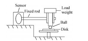
The friction and wear tests were conducted on a ball-on-disc tribometer in a vacuum level of~10-4 Pa under dry condition at room temperature. The contact schematic diagram of the friction couple is shown in Fig. 2. Friction tests were conducted under a load of 1 N over a period of 1 h with the steel ball fixed and the disc samples rotated at a sliding speed of 0.12 m/s. The steel ball is made of GCr15 stainless steel (the chemical composition in terms of mass fraction % is shown in Table 1) and is 3.175 mm in diameter and cleaned in acetone by ultrasonic cleaner before the test. The wear rate was calculated from the relationship[27]:
Figure 2.
The contact schematic diagram for the friction couple
 Table 1.
The chemical composition (mass fraction, %) of the GCr15 steel ball
Table 1.
The chemical composition (mass fraction, %) of the GCr15 steel ball
Element content (%) C Mn Si P S Cr 0.95-1.05 0.25-0.45 0.15-0.35 ≤0.025 ≤0.025 1.40-1.65 Table 1. The chemical composition (mass fraction, %) of the GCr15 steel ballwhere k is the wear rate (mm3×(Nm)-1), WV is the volume of the removed material (mm3), FN is the load in Newton (N) and s is the sliding distance in meter (m).
Proton Irradiation
Proton irradiation was carried out in a ground-based simulation facility in Lanzhou Institute of Chemical Physics, Chinese Academy of Sciences. The irradiation was performed under vacuum environment (~10-3Pa) at an accelerative voltage of 15, 20 and 25 kV, respectively. The flux of the proton was determined to be 2.5 × 10¹⁴ protons/(cm2·s), and the dose was determined to be 3 × 10¹⁶ protons/cm2.
Preparation of Materials
In the experiments, the PTFE (M-18F) powder with an average grain size of 25 μm was supplied by Daikin Fluorochemicals Co., Ltd. Firstly, the PTFE powder was added to a mold and cold pressed under a pressure of 40 MPa for 20 min. Then, the PTFE material was taken out from the mold and sintered in an oven. The temperature program of sintering is shown in Fig. 1. At the end of the sintering, the specimens were spontaneously cooled in the oven to room temperature.
 Figure 1.
The temperature program of sintering
Figure 1.
The temperature program of sintering
RESULTS AND DISCUSSION
Distribution of Protons in Substrate
In this experiment, the PTFE was irradiated by protons with a flux of 2.5 × 10¹⁴ protons/(cm2·s) and different energies of 15, 20 and 25 keV. The depth distribution and the depths of the peaks for different energies of protons were calculated by using Transport of Ions in Matter (TRIM), as shown in Figs. 3(a) and 3(b), respectively. TRIM is an accepted model of ion implantation, which has been carefully calibrated with empirical data since its inception[28]. It can be seen from Fig. 3(a) that the proton irradiation showed a depth distribution in the substrate. It is clear from Fig. 3(b) that the depths of the peaks increased linearly with the increase of proton energy.
 Figure 3.
Depth distribution (a) and depths of the peaks (b) for different energies of proton calculated by using TRIM
Figure 3.
Depth distribution (a) and depths of the peaks (b) for different energies of proton calculated by using TRIM
Changes in Surface Morphology
The SEM surface morphologies of PTFE before and after proton irradiation are shown in Fig. 4. It is obvious that the surface morphology of the specimen was undamaged before proton irradiation, whereas it was seriously eroded and the surfaces gradually changed into “honeycomb-like” structures when specimens exposed to the proton irradiation environment, and the degree of erosion increased with increasing of acceleration voltage. The reason was that when the specimens were irradiated by protons, the surfaces of the specimens would undergo a process of complex chemical and physical reactions, which produced volatile products and then removed from the surface. All of the above actions resulted in the change of the surface morphologies.
 Figure 4.
SEM photographs of the samples before (a) and after (b: 15 keV, c: 20 keV, d: 25 keV) proton irradiation
Figure 4.
SEM photographs of the samples before (a) and after (b: 15 keV, c: 20 keV, d: 25 keV) proton irradiation
Changes in Surface Chemical Structure
In order to confirm the above expectation, the molecular structure on the surface of the PTFE samples was investigated. Figure 7 presents the ATR-FTIR spectra of PTFE surfaces before and after proton irradiation. It is evident that the intensity of the characteristic peaks at 1145 and 1204 cm-1 corresponding to C-F vibrations after proton irradiation was similar to that of the pristine sample. As a result, it is expected that PTFE still keeps some primary chain structure after proton irradiation. However, some broadening at the bottom of the C-F vibrations peaks at 1715, 2851 and 2920 cm-1 can be found from Fig. 7, which was caused by the degradation of the chain structures and the formation of the new groups.
 Figure 7.
The ATR-FTIR spectra of PTFE surface before and after proton irradiation
Figure 7.
The ATR-FTIR spectra of PTFE surface before and after proton irradiation
On one hand, the appearance of the C=O peak at 1715 cm-1 in ATR-FTIR spectra of treated PTFE indicates that oxidation processes of PTFE with the residual oxygen in the vacuum chamber occurred in a thin surface layer after proton irradiation. On the other hand, the characteristic peaks of C-H at 2851 and 2920 cm-1 demonstrate that some C-F bonds were broken during proton irradiation, the F might combine with proton to produce a HF released from the sample surface, and the C combine with proton to produce C-H band. So it can be speculated that some complex chemical reactions occurred during the irradiation.
Changes in Surface Chemical Composition
In order to investigate the changes of the chemical composition of PTFE, XPS spectra of PTFE before and after proton irradiation were recorded and are shown in Fig. 5. It can be seen that the PTFE was characterized by the C1s peak at approximately 291.7 eV and F1s peak at 689.0 eV, which were both weakened significantly after irradiation. The relative atomic concentrations of C and F in the surface of samples before and after irradiation are listed in Table 2. The results indicate that the relative concentration of C increased from 34.1% to 45.8% and 46.6%, while it decreased from 65.9% to 54.2% and 53.4% for F after 15 and 25 keV proton irradiation, respectively. It is noteworthy to observe a new peak at the binding energy of about 532.2 eV after the proton irradiation, which is corresponding to O element (C-O or C=O). This indicates that the degradation took place on the sample surface, and some bonds such as C-C and C-F were broken during proton irradiation, then the formed C radicals reacted with the remaining oxygen in the vacuum chamber. For F atoms, which were covered on the surface of PTFE molecular chains, the C-F bonds were destroyed and followed by the release of volatile products, resulting in the increase of C content and decrease of F content on the sample surface.
 Figure 5.
XPS spectra of PTFE before and after proton irradiation
Table 2.
The relative atomic concentration on the surface of samples before and after proton irradiation
Figure 5.
XPS spectra of PTFE before and after proton irradiation
Table 2.
The relative atomic concentration on the surface of samples before and after proton irradiation
Samples Surface composition (%) C F C/F Before irradiation 34.1 65.9 0.52 15 keV irradiation 45.8 54.2 0.85 25 keV irradiation 46.6 53.4 0.87 Table 2. The relative atomic concentration on the surface of samples before and after proton irradiationThe details of the C1s and F1s spectra of PTFE before and after proton-irradiation are shown in Fig. 6. For the C1s spectra, it is clear that it was a symmetric curve at the binding energy of 291.7 eV before irradiation, while it was an asymmetric curve after 25 keV proton irradiation. This can be simulated by using five Gaussian peaks located at 293.1, 291.7, 288.9, 286.7 and 284.6 eV. The peak at 293.1 eV was ascribed to -CF3, and the ones at 291.7, 288.9, 286.7 and 284.6 eV were corresponding to -CF2-CF2-, -CF2-CHF-or -CHF-CHF-, -CH2-CHF-or -CH2-CF2-and -CH2-CH2-, respectively. In addition, the binding of C=O and C-O were at about 288.5 and 286.6 eV, respectively[29]. For the F1s spectra, the intensity for the irradiated sample was weaker than the un-irradiated one. It was expected that after irradiation the molecular chain was broken and then most likely reacted with proton, while volatile product containing F element might have formed and evacuated from the sample surface.
 Figure 6.
C1s and F1s XPS spectra of PTFE before and after proton irradiation
Figure 6.
C1s and F1s XPS spectra of PTFE before and after proton irradiation
Friction and Wear Properties
As discussed before, the proton irradiation could induce the oxidation and degradation of PTFE molecular chains, which have great effects on the molecular structure and chemical composition of sample surface. In order to investigate the effects of proton irradiation on the tribological properties of PTFE, the friction and wear tests of PTFE before and after proton irradiation were conducted on a ball-on-disc tribometer in a vacuum level of~10−4 Pa under dry condition at room temperature. The friction coefficient and wear rate gained in present experiment are shown in Figs. 8(a) and 8(b), respectively. From Fig. 8(a), it can be seen that the initial friction coefficients of the specimens irradiated by proton were obviously higher than the un-irradiated one, which may be due to the degradation of the samples and the increase of the surface roughness. Meanwhile, the friction coefficient of samples after proton irradiation had two jumping points in sliding process, and the time interval between the two jumping points increased with the increasing of the proton irradiation energy. It can be expected that the occurrence of the jumping points in the sliding process for the proton irradiated samples is related to the depth distribution of the proton. From the TRIM result shown in Fig. 3, it can be concluded that the first jumping point resulted from the contact of the steel ball with upper interface of the proton distribution layer (Fig. 9a), and the second one was due to the contact with other interface (Fig. 9b). At the same time, it can be seen from Fig. 8(b) that the wear rate decreased with increasing proton energy. When PTFE was irradiated by proton, the molecular bonds have been broken and then might form new bonds between different PTFE molecular chains. The above actions resulted in the formation of cross-link structures of PTFE, which may increase the cohesive strength and shear resistant capacity and as a result decrease the wear rate and increased the friction coefficient[30].
 Figure 8.
The friction coefficient (a) and wear rate (b) of specimens before and after proton irradiation
Figure 8.
The friction coefficient (a) and wear rate (b) of specimens before and after proton irradiation
 Figure 9.
The contact schematic diagram for the steel ball with distribution layer of protons
Figure 9.
The contact schematic diagram for the steel ball with distribution layer of protons
At the same time, the SEM micrographs of the worn surfaces of PTFE and wear scars on the steel balls before and after proton irradiation are shown in Figs. 10(a-d) and 10(e-h), respectively. The worn surface of the un-irradiated sample showed adhesion and plastic deformation (Fig. 10a), indicating that adhesive wear took the dominant wear mechanism. Meanwhile, a lot of wear debris were formed on the steel ball (Fig. 10e), which corresponds to the high wear rate of pristine PTFE. For the 15 keV proton irradiated sample, the wear surface and scar were similar to the pristine one (Figs. 10b and 10f). The 20 and 25 keV proton irradiated ones showed relatively smooth worn surfaces (Figs. 10c and 10d), which indicate that fatigue and abrasive wear took the dominant wear mechanism. The cross-link of the molecular chains resulted from the proton irradiation increased the surface hardness and shear resistant capacity of the samples, and thus less and smaller wear debris were formed on the steel balls (Figs. 10g and 10h).
 Figure 10.
SEM micrographs of the worn surfaces of the composites and wear debris on the steel balls (a, b, c and d are the worn surfaces; e, f, g and h are the wear debris of un-irradiated, 15 keV, 20 keV and 25 keV proton irradiated PTFE, respectively.)
Figure 10.
SEM micrographs of the worn surfaces of the composites and wear debris on the steel balls (a, b, c and d are the worn surfaces; e, f, g and h are the wear debris of un-irradiated, 15 keV, 20 keV and 25 keV proton irradiated PTFE, respectively.)
CONCLUSIONS
Proton irradiation induced bond break and cross-link of PTFE, which resulted in the formation of new bond groups and volatile products. Irradiation changed the surface chemical composition and morphology of the samples.
Irradiation changed the friction coefficient of the samples. The wear rate decreased with the increasing proton irradiation energy. The main wear mechanism of the un-irradiated sample and the 15 keV proton irradiated one was adhesive wear, while that of the 20 and 25 keV proton irradiated ones was mainly fatigue and abrasive wear.
-
-
[1]
Grossman, E. and Gouzman, I., Nucl. Instrum. Methods Phys. Res. Sect. B, 2003, 208:48 doi: 10.1016/S0168-583X(03)00640-2
-
[2]
Wang, X.L., Zhou, F. and Liu, W.M., J. Appl. Polym. Sci., 2011, 120:329 doi: 10.1002/app.v120.1
-
[3]
Zhao, X.H., Shen, Z.G., Xing, Y.S. and Ma, S.L., Polym. Degrad. Stab., 2005, 88:275 doi: 10.1016/j.polymdegradstab.2004.11.002
-
[4]
Packirisamy, S., Schwam, D. and Litt, M.H., J. Mater. Sci., 1995, 30:308 doi: 10.1007/BF00354390
-
[5]
Hossain, U.H., Muench, F. and Ensinger, W., RSC Adv., 2014, 4:50171 doi: 10.1039/C4RA04635H
-
[6]
Shimamura, H. and Nakamura, T., Polym. Degrad. Stab., 2010, 95:21 doi: 10.1016/j.polymdegradstab.2009.10.017
-
[7]
Hwang, I.T., Kuk, I.S., Jung, C.H., Choi, J.H., Nho, Y.C. and Lee, Y.M., ACS Appl. Mater. Interfaces, 2011, 3:2235 doi: 10.1021/am200630p
-
[8]
Pei, X., Wang, Q. and Chen, J., Appl. Surf. Sci., 2006, 252:3878 doi: 10.1016/j.apsusc.2005.06.003
-
[9]
De Groh, H.C., Puleo, B.J., Waters, D.L. and Miller, S.K., J. Appl. Polym. Sci., 2015, 132:41662
-
[10]
Timmers, H., Gladkis, L.G., Warner, J.A., Byrne, A.P., del Grosso, M.F., Arbeitman, C.R., Garcia-Bermudez, G., Geruschke, T. and Vianden, R., Nucl. Instrum. Methods Phys. Res. Sect. B, 2010, 268:2119 doi: 10.1016/j.nimb.2010.02.019
-
[11]
Wang, Y., Wang, H. and Yan, F., Surf. Interface Anal., 2009, 41:399 doi: 10.1002/sia.v41:5
-
[12]
Pei, X., Wang, Q. and Chen, J., Wear, 2005, 258:719 doi: 10.1016/j.wear.2004.10.002
-
[13]
Gao, M., Liu, B.J., Gao, L.C., Yin, P.G. and Jiang, L., Chinese J. Polym. Sci., 2013, 31:83 doi: 10.1007/s10118-013-1213-z
-
[14]
Zhang, L.X., Yang, S.Q. and He, S.Y., Chinese J. Polym. Sci., 2003, 21:563
-
[15]
Liu, B., Pei, X., Wang, Q., Sun, X. and Wang, T., Appl. Surf. Sci., 2011, 258:1097 doi: 10.1016/j.apsusc.2011.09.041
-
[16]
Huang, T., Li, T., Xin, Y., Jin, B., Chen, Z., Su, C., Chen, H. and Nutt, S., RSC Adv., 2014, 4:19814 doi: 10.1039/c4ra01964d
-
[17]
Shi, Y., Feng, X., Wang, H. and Lu, X., J. Mater. Sci., 2007, 42:8465 doi: 10.1007/s10853-007-1767-7
-
[18]
Xu, Y.K., Huang, C. and Jin, X.Y., J. Appl. Polym. Sci., 2016, 133:43553
-
[19]
Khan, M.S., Lehmann, D., Heinrich, G. and Franke, R., Wear, 2009, 266:200 doi: 10.1016/j.wear.2008.06.014
-
[20]
Ennis, C.P. and Kaiser, R.I., Phys. Chem. Chem. Phys., 2010, 12:14884 doi: 10.1039/c0cp00493f
-
[21]
Barylski, A., Maszybrocka, J., Kupka, M., Aniolek, K. and Kaptacz, S., J. Appl. Polym. Sci., 2015, 132:42348
-
[22]
Kitamura, A., Kobayashi, T., Meguro, T., Suzuki, A. and Terai, T., Nucl. Instrum. Methods Phys. Res. Sect. B, 2009, 267:1638 doi: 10.1016/j.nimb.2009.01.123
-
[23]
Ishikawa, K., Sumi, N., Kono, A., Horibe, H., Takeda, K., Kondo, H., Sekine, M. and Hori, M., J. Phys. Chem. Lett., 2011, 2:1278 doi: 10.1021/jz2002937
-
[24]
Kitamura, A., Kobayashi, T., Meguro, T., Suzuki, A. and Terai, T., Surf. Coat. Technol., 2009, 203:2406 doi: 10.1016/j.surfcoat.2009.02.038
-
[25]
Sharma, A.K. and Sridhara, N., Adv. Space. Res., 2012, 50, 1411 doi: 10.1016/j.asr.2012.07.010
-
[26]
Liu, B., Pei, X., Wang, Q., Sun, X. and Wang, T., Surf. Interface Anal., 2012, 44:609 doi: 10.1002/sia.v44.5
-
[27]
Khan, M.S., Franke, R., Gohs, U., Lehmann, D. and Heinrich, G., Wear, 2009, 266:175 doi: 10.1016/j.wear.2008.06.012
-
[28]
Warner, J.A., Gladkis, L.G., Geruschke, T., Vianden, R., Smith, P.N., Scarvell, J.M., Zeitz, W.D. and Timmers, H., Wear, 2010, 268:1257 doi: 10.1016/j.wear.2010.01.021
-
[29]
Peng, G., Yang, D. and He, S., Polym. Adv. Technol., 2003, 14:711 doi: 10.1002/(ISSN)1099-1581
-
[30]
Liu, W., Yang, S., Li, C. and Sun, Y., Thin Solid Films, 1998, 323:158 doi: 10.1016/S0040-6090(97)01034-1
-
[1]
-

 扫一扫看文章
计量
- PDF下载量: 0
- 文章访问数: 799
- HTML全文浏览量: 50
 下载:
下载:
