 Figure 1.
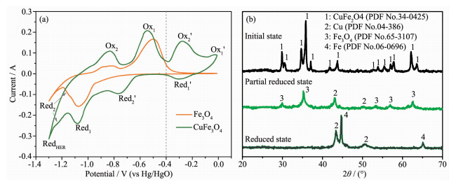
self-assembly of Fe/Cu nanocomposite electrode from t-CuFe2O4: (a) Redox behavior of t-CuFe2O4 compared to Fe3O4; (b) Phase transition upon the self-assembly process
Figure 1.
self-assembly of Fe/Cu nanocomposite electrode from t-CuFe2O4: (a) Redox behavior of t-CuFe2O4 compared to Fe3O4; (b) Phase transition upon the self-assembly process
Citation:
LIU Ping, ZHU Ding, YANG Jun, HUANG Lan-Xiang, CHEN Yun-Gui. Electrochemically Self-Assembled Fe/Cu Nanocomposite with Improved High-Rate and Low-Temperature Performances for Nickel-Iron Alkaline Battery[J]. Chinese Journal of Inorganic Chemistry,
2017, 33(5): 779-786.
doi:
10.11862/CJIC.2017.089

电化学自组装Fe/Cu纳米复合材料对铁镍电池高倍率及低温性能改性
摘要:
通过在碱液中阴极还原铁酸铜 (t-CuFe2O4) 简便地实现了纳米Fe/Cu复合材料的自组装.采用循环伏安 (CV) 与X射线衍射 (XRD) 分析了自组装过程中的相变.通过透射电镜 (TEM)、选区电子衍射 (SAED) 以及扫描透射-能谱分析 (STEM-EDX) 的表征可以发现电结晶得到的铁、铜纳米颗粒分布均匀且接触紧密.当用于铁镍电池负极时, Fe/Cu纳米复合电极展现了较好的放电容量与充电接收能力, 并具备优异的高倍率与低温性能.当电流密度高达4 500 mA·gFe-1或运行温度仅为-40℃时, 该电极仍拥有很好的输出容量与电位特性.线性扫描伏安 (LSV) 分析证明了该电极中原位生成的Cu纳米颗粒催化了活性Fe的阳极溶解动力学性能, 因而明显改善了电极的高倍率与低温放电性能.
English
Electrochemically Self-Assembled Fe/Cu Nanocomposite with Improved High-Rate and Low-Temperature Performances for Nickel-Iron Alkaline Battery
Abstract:
Fe/Cu nanocomposite was simply self-assembled through the cathodic decomposition of tetragonal spinel CuFe2O4 (t-CuFe2O4) in alkaline solution. The phase transition from t-CuFe2O4 to Cu/Fe3O4, and eventually to Fe/Cu composite was monitored by cyclic voltammetry (CV) and X-ray powder diffraction (XRD). Transmission electron microscope (TEM), selected area electron diffraction (SAED) and scanning TEM-energy dispersive X-ray (STEM-EDX) observations showed that the electro-crystallized copper and iron nanoparticles dispersed homogeneously and contacted intimately. When the Fe/Cu nanocomposite electrode was tested as the anode for nickel-iron (Ni-Fe) rechargeable battery, it exhibited enhanced discharge capacity, charge-acceptance and especially remarkable high-rate and low-temperature performances. Excellent capacity output and potential characteristics were achieved at high discharge current density (4 500 mA·gFe-1) or low operation temperature (-40℃), respectively. Linear scanning voltammetry (LSV) analyses demonstrated that the incorporation of in situ formed copper facilitated the anodic kinetics of active iron, resulting to the markedly enhanced high-rate and low-temperature discharge-ability of electrode.
-
By virtue of its long service life, low cost, environmental friendliness, and excellent resistance to both physical and electrochemical abuse, Ni-Fe alkaline battery has been widely developed for traction, electric vehicles and stationary applications. Additionally, it may be a suitable substitution for lead-acid or nickel-cadmium battery as the large-scale energy storage system (>1 MW) in the view of environmental protec-tion[1-2]. However, the bottlenecks of Fe anode, namely, extremely poor high-rate and low-temperature perfor-mances, low utilization of active iron and hydrogen evolution on the electrode lead to the decline in usage of Ni-Fe battery[3]. Over several decades of efforts, res-earchers have circumvented some of these problems to a substantial degree[4-20]. Various metal sulfides are demonstrated to markedly improve the capacity and the charge retention of Fe anode[4-9, 15]. Hydrogen-oxygen recombinant catalyst is used to successfully suppress the gas evolution in battery[11]. And nanomaterial elec-trodes are confirmed to considerably enhance the utilization of active iron[10, 17-18, 20]. However, few investi-gations have simultaneously focused on the perfor-mances of Fe anode operated under extremely condi-tions, that is, low-temperature or high-rate. Since most of the present Fe alkaline electrodes are merely adapted to operation temperature above-15 ℃ and discharge current density below 300 mA·gFe-1 [3, 5-6, 8-16], significant improvements are urgently needed if we want to extend the application scope of Ni-Fe battery.
Slow anodic kinetics of active iron generally account for the poor low-temperature and high-rate performances of Fe alkaline electrode. The copper incorporation seems to be an effective way because Cu particles can effect as high conductive nucleation cores to greatly assist the anodic dissolution-deposition process of iron species. Recently, Kao and co-workers synthesized Fe/Cu nanocomposite via NaBH4 reduction, which exhibited an outstanding capacity delivery at the current density up to 3200 mA·gFe-1 [20]. This study put forward an effective route to improve the poor rate performance of Fe anode, but the involved preparation are somewhat elaborate for practice, and the low-temperature performance and anodic kinetics of electrode are not referred.
In this study, a facile self-assembly of Fe/Cu nanocomposite through the cathodic decomposition of t-CuFe2O4 precursor is proposed. The electrochemical performances, especially the high-rate and low-temperature discharge-ability of Fe/Cu nanocomposite electrode are investigated in detail. In addition, LSV is employed to analyze the effect of copper incorporation on the anodic kinetics of iron.
1 Experimental
1.1 Syntheses of t-CuFe2O4
t-CuFe2O4 was prepared by a co-precipitation method[21]. Briefly, the aqueous solution of NaOH (5 mol·L-1) was added to the aqueous solution which contained 0.125 mol·L-1 FeCl3·6H2O and 0.062 5 mol·L-1 CuCl2·2H2O. The as-formed brown suspension was stirred at 373 K for 2 h. Then the precipitate was filtered and washed with deionized water and alcohol, and dried at 373 K for 12 h. Finally, the precursor was calcined at 1 073 K for 2 h to form pure t-CuFe2O4 phase.
1.2 self-assembly and characterization of Fe/Cu nano-composite electrode
Galvanostatic charging technique was used to induce the reduction of t-CuFe2O4 to selF-assemble the Fe/Cu nano-composite electrode. The working electrode was fabricated by pasting a slurry mixture of 80% t-CuFe2O4, 15% acetylene black and 5% PVA onto a nickel foam (1 cm×1 cm) and then dried at 373 K for 12 h. Electrochemical experiments were performed using a three-electrode cell including one working electrode, four sintered Ni (OH)2/NiOOH counter elec-trodes and one Hg/HgO reference electrode. The elec-trolyte comprised of 8 mol·L-1 KOH and 0.05 mol·L-1 Na2S. The cathodic current density was kept at 300 mA·goxide-1 and the reduction time was 2 h.
The phase transition process was monitored by CV (Par2273 potentiostat with the potential range of 0 to-1.4 V at a sweep rate of 5 mV·s-1) and XRD (Dandong DX-2600 with Cu Kα radiation, λ=0.154 18 nm, U=35 kV, I=25 mA, 2θ=20°~70°). TEM, SAED, STEM-EDX and high-resolution transmission electron microscope (HRTEM) analyses were conducted on a Tecnai G220 S-TWIN microscope to observe morpho-logy, elemental distribution and interface configuration of the as-formed Fe/Cu nanocomposite.
1.3 Electrochemical measurements of Fe/Cu nano-composite electrode
Galvanostatic discharging-charging tests were conducted to measure the electrochemical performan-ces of Fe/Cu nanocomposite electrode. The capacity and charge-acceptance of Fe/Cu nanocomposite elec-trode were evaluated with a current density of 300 mA·gFe-1 under 30 ℃. To investigate the high-rate performance, the electrode was charged with a 300 mA·gFe-1 current density for 2 h, and the fully charged electrode was discharged at 50, 300, 1 500 and 4 500 mA·gFe-1 under 30 ℃, respectively. To investigate the low-temperature performance, the fully charged elec-trode was discharged under 30, 0, -20 and-40 ℃ at 50 mA·gFe-1, respectively. The tests at lower tempera-tures were conducted after the system was held at a constant temperature for 2 h. LSV was employed to study the anodic kinetic properties of Fe/Cu nanoco-mposite electrode with various scan rates using the Par2273 potentiostat.
2 Results and discussion
2.1 self-assembly of Fe/Cu nanocomposite electrode from t-CuFe2O4
Fig. 1(a) illustrates the electrochemical redox behaviors of t-CuFe2O4 in aqueous alkaline solution. Four pairs of redox peaks appear in the CV curve of t-CuFe2O4. Referring to the CV curve of Fe3O4, two pairs of cathodic/anodic peaks Red1/Ox1 and Red2/Ox2 can be attributed to the reduction/oxidation of Fe3+/2+ ⇆ Fe2+ and Fe2+ ⇆ Fe0, respectively. The additional redox couples, marked as Red1′/Ox1′ and Red2′/Ox2′, correspond to the redox reactions of Cu2+ ⇆ Cu+ and Cu+ ⇆ Cu0 [22], respectively. Obviously, along the cathodic direction, copper cations are preferentially reduced to metallic state, then ferric iron is reduced to ferrous iron, and eventually to elemental iron. From a thermodynamics point of view, Cu can keep metallic state while Fe undergoes the reversibly faradic reactions (Fe3+ ⇆ Fe0) in a certain potential range (the left area of the dot in Fig.(1a)).
Figure 1.
self-assembly of Fe/Cu nanocomposite electrode from t-CuFe2O4: (a) Redox behavior of t-CuFe2O4 compared to Fe3O4; (b) Phase transition upon the self-assembly process
Fig. 1(b) records the phase transition during the self-assembly of Fe/Cu nanocomposite from t-CuFe2O4. Initially, only t-CuFe2O4 phase can be detected. Then t-CuFe2O4 decomposes into Cu/Fe3O4 composite after Red2′ reaction. Finally, magnetite converts into metallic Fe while Cu remains stable. The elemental Cu and Fe exist not as alloy or solid-solution but as two separated phases due to the immiscibility. The crystallite size of each phase is calculated to be 54.9 nm (Cu) and 61.8 nm (Fe) using the Scherrer equation, suggesting the self-assembly of Fe/Cu composite at the nanoscale.
TEM image also confirms the nano-level combination of iron and copper (Fig. 2(a)). Indeed, the average particle size is below 100 nm and consistent with XRD results. SAED (Fig. 2(a), Inset) presents a clear spots and rings pattern demonstrating the nanocrystalline nature. Judging from the d-spacing, the five distinct rings can be indexed to the (111) and (200) reflections of Cu, and to the (110), (220) and (221) reflections of Fe, respectively. Element mapping for either Fe or Cu (Fig. 2(b)) reveals the homogeneous dispersion of two phases, which can be further proved by the HRTEM image (Fig. 2(c)), where two kinds of nanoparticles with different contrasts distribute unifo-rmly. The inset of Fig. 2(c) gives more information about the crystal structure and the interface configura-tion of the nanocomposite. The lattice fringes illustrate the well crystallinity of two nanoparticles and exhibit the interplanar distances of 0.207 nm (the dark) and 0.141 nm (the light) that are characteristic of copper (111) planes and iron (200) planes, respectively, agreeing well with the analyses of XRD and SEAD. An intimate contact between two metallic grains is pronounced around the phase boundary.
 Figure 2.
Characterization of Fe/Cu nanocomposite electrode: (a) TEM overview; (b) STEM-EDX element mapping for Fe and Cu at a random area; (c) HRTEM image
Figure 2.
Characterization of Fe/Cu nanocomposite electrode: (a) TEM overview; (b) STEM-EDX element mapping for Fe and Cu at a random area; (c) HRTEM image
Considering that the bonding nature of Cu-O is weaker than that of Fe-O in t-CuFe2O4[23], and that the equilibrium potentials of Cu2+ ⇆ Cu0 reactions are more positive than those of Fe3+ ⇆ Fe0 reactions, copper cations at the octahedral sites of t-CuFe2O4 are readily and preferentially reduced and migrated from the lattice upon the electrochemical reduction. Accompanied with the phase separation, the copper species dissolve and precipitate homogeneously on the surface of Fe species. The in situ formed Cu nanoparticles can uniformize the cathodic current distribution and suppress the coalescence of Fe grains to facilitate the electro-crystallization of Fe. Thus, Fe particles finely disperse and strongly contact within Cu nanoparticles to form the well-architectured Fe/Cu nano-composite.
2.2 Electrochemical performances of Fe/Cu nano-composite electrode
Fig. 3 shows the typical charge-discharge profiles of Fe/Cu nanocomposite electrode, and the traditional Fe electrode is introduced for comparison. Both electrodes exhibit two pairs of potential plateaus, corresponding to Red1/Ox1 and Red2/Ox2 in Fig. 1(a), respectively. Briefly, Red1/Ox1 involves the diffusion of protons between the solid lattices of Fe3O4 and Fe (OH)2. Red2/Ox2 represents the cathodic electro-crystallization and the anodic dissolution of Fe, respectively. The extra plateau in both charging curves (dot line) links to the hydrogen evolution reaction (HER). For the traditional Fe electrode, the potential plateaus of Red2 and HER tend to overlap, and a lot of charging current is consumed to HER instead of Fe electro-crystallization, causing a poor charge-acceptance. On the other hand, Fe/Cu nanocomposite electrode shows a relatively low polarization of Red2, thus Fe species can be mainly reduced before the electrolysis of water. Furthermore, both the discharge capacity and the potential characteristics of Fe/Cu electrode are markedly improved as compared to those of Fe elec-trode, suggesting that the incorporation of Cu enhances the utilization and anodic kinetics of active iron.
 Figure 3.
Typical charge-discharge profiles of Fe and Fe/Cu nano-composite electrodes
Figure 3.
Typical charge-discharge profiles of Fe and Fe/Cu nano-composite electrodes
In the practical application of Fe alkaline elec-trode, only the Red2/Ox2 redox is involved[3]. So the following discussions on the high-rate and low-temperature discharge-ability mainly focus on the first discharge plateau. Fig. 4 shows the comparison of the discharge curves for Fe and Fe/Cu electrodes at various current densities. Fe/Cu electrode displays a significantly enhanced high-rate performance than that of Fe electrode. When the current density increases from 50 to 1 500 mA·gFe-1, the capacity retention of Fe/Cu electrode attains 72%, which is almost twice than that of Fe electrode (37%). When the current density further increases up to 4 500 mA·gFe-1, Fe/Cu electrode still remains ~50% capacity output, whereas Fe electrode is close to failure. Besides, the potential plateau characteristics of Fe/Cu electrode under increased current density is also improved. The midpoint potential (Emid) of Fe/Cu electrode at each current density is 0.94, 0.93, 0.9 and 0.83 V (vs Hg/HgO), respectively, and the corresponding value of Fe electrode is 0.91, 0.86, 0.78 and 0.7 V (vs Hg/HgO), respectively. Clearly, the anodic polarization of Ox2 is significantly relieved for Fe/Cu nanocomposite electrode.
 Figure 4.
Discharge curves of Fe and Fe/Cu nanocomposite electrodes at various current densities
Figure 4.
Discharge curves of Fe and Fe/Cu nanocomposite electrodes at various current densities
There are similar regulations between the influence of the low-temperature and the high-rate on the discharge-ability of Fe and Fe/Cu electrodes (Fig. 5). With the temperature decreasing from 30 to-40 ℃, both electrodes suffer capacity deterioration and increasing polarization. However, the temperature influence on the discharge-ability for Fe/Cu electrode is much smaller as compared to Fe electrode. At 30 ℃, the capacity and Emid of Fe/Cu electrode are slightly higher than those Fe/Cu electrode, but the gaps between capacity and midpoint potential of two electrodes gradually widens with decreasing tempera-ture. At-40 ℃, Fe/Cu electrode is able to deliver a capacity of 211 mAh·gFe-1, which accounts for 61% of its capacity at room-temperature, and is more than seven times higher than the capacity output of Fe electrode (30 mAh·gFe-1). Moreover, the Emid value of Fe/Cu electrode is nearly 100 mV higher than that of Fe electrode at-40 ℃. It is clear that both the capacity output and the depolarization of the Fe/Cu nanocom-posite electrode are significantly superior to those of the traditional Fe electrode in low-temperature environment. As previously stated, the copper species dissolve and precipitate homogeneously on the surface of Fe species. The in situ formed Cu nanoparticles can uniformize the cathodic current distribution and suppress the coalescence of Fe grains. Cu nanopar-ticles can also effect as high conductive nucleation cores to greatly promote the anodic dissolution-deposition process of Fe species, thereby significantly improve the performance of the electrode at low temperature.
 Figure 5.
Discharge curves of Fe and Fe/Cu nanocomposite electrodes at various operating temperatures
Figure 5.
Discharge curves of Fe and Fe/Cu nanocomposite electrodes at various operating temperatures
2.3 Anodic kinetics of Fe/Cu nano-composite electrode
The excellent high-rate and low-temperature performances of Fe/Cu nanocomposite electrode can be attributed to the greatly enhanced anodic kinetics of Ox2 reaction. To study the effect of Cu incorporation on the kinetics of Ox2 reaction, LSV tests at various scan rates are conducted and the results are shown in Fig. 6(a~b). Both the current response at each scan rate and the increment of current density with the scan rate are much higher for Fe/Cu electrode as opposed to Fe electrode. This implies that a much higher reaction rate of Ox2 is achieved for Fe/Cu electrode. Furthermore, the shift in anodic peak potential is minimal for Fe/Cu electrode, indicating that Fe/Cu electrode suffers relatively low anodic polarization as previous discussion.
 Figure 6.
Anodic LSVs of Fe electrode (a) and Fe/Cu electrode (b) under various scan rates
Figure 6.
Anodic LSVs of Fe electrode (a) and Fe/Cu electrode (b) under various scan rates
The variations of peak current density (Ip) with square root of the scan rate (v1/2) for iron electrodes with and without Cu incorporation are plotted in Fig. 7. The peak current densities of both electrodes varies linearly with the square root of scan rate. Such a linear relationship between Ip and v1/2 for Ox2 can be expressed as[24]:
 Figure 7.
Relationship between Ip and v1/2 for Fe and Fe/Cu nano-composite electrodes
Figure 7.
Relationship between Ip and v1/2 for Fe and Fe/Cu nano-composite electrodes
Here K is the specific reaction rate constant for the metal dissolution reaction, which directly characterizes the reaction rate. Consequently, the kinetic properties of iron anodic dissolution can be largely evaluated from the slope of Ip to v1/2 in Fig. 7, and the Fe/Cu nanocomposite electrode evidently attains a much higher rate for Ox2 reaction than Fe electrode.
The anodic reaction of iron electrode (Ox2) can be represented as:
It is a typical 'dissolution-deposition' process which proceeds through the following steps[25-26]:
For the traditional Fe electrode, the low solubility of intermediates (HFeO2-) is responsible for the extremely poor high-rate and low-temperature performances[3]. Due to the low solubility, HFeO2- is prone to supersaturation before diffusing in the electr-olyte, thereby the insoluble and insulating Fe (OH)2 tends to precipitate at or near the anodic reaction site and block the active surface of Fe. In this study, the introduction of Cu significantly promotes the kinetics of Ox2 reaction as is confirmed above. Since the Cu incorporation can hardly affect the solubility of HFeO2- in the alkaline solution, it is reasonable to conclude that Cu nanoparticles play an important role in altering the passivation behavior of active iron. Presumably, these Cu particles of tight adhesion with active Fe phase act as the heterogeneous nucleation cores for Fe (OH)2 deposition, which suppresses the cover of Fe (OH)2 on the reaction sites upon discharge, and keeps the high effective interface between active Fe and electrolyte. Additionally, Cu nanoparticles of high electronic conductivity distributes homogeneously through the whole electrode, which constructs a high conductive network to guarantee the electrons transport when electrode suffers a severely passivation, signifi-cantly reducing the anodic polarization of electrode upon discharge.
3 Conclusions
In summary, a facile self-assembly of Fe/Cu nanocomposite from the cathodic decomposition of t-CuFe2O4 is presented. The electro-crystallized copper and iron nanoparticles disperse homogeneously and contact intimately. When the as-prepared Fe/Cu nanocomposite electrode was tested as the anode for Ni-Fe alkaline battery, it exhibits enhanced discharge capacity, charge-acceptance and especially remarkable high-rate and low-temperature performances. Excellent capacity output and potential plateau characteristics can be achieved even at 4 500 mA·gFe-1 or-40 ℃. It is demonstrated that the incorporation of copper promotes the anodic kinetics of active iron upon the dissolution-deposition process, resulting to the greatly enhanced high-rate and low-temperature discharge-ability of the electrode.
The presented route still has room for optimization. Our further work shows that by adjusting the atomic ratio nCu/nFe in the pristine binary oxide can make the electrode to output much higher capacity while remaining the excellent rate performance (unpublished). The employment of other reductive methods, such as pulse charging or H2 reduction, may assist the Fe/Cu composite to get more ideal morphology for practice. Furthermore, such route also has a promising application in Fe-air and Fe-AgO rechargeable alkaline batteries, which are bothered by the poor high-rate and low-temperature performances of Fe alkaline anodes as well.
-
-
[1]
Shukla A K, Venugopalan S, Hariprakash B. J. Power Sources, 2001, 100:125-148 doi: 10.1016/S0378-7753(01)00890-4
-
[2]
Ibrahim H, Ilinca A, Perron J. Renewable Sustainable Energy Rev., 2008, 12:1221-1250 doi: 10.1016/j.rser.2007.01.023
-
[3]
Brodd R J, Linden D, Reddy T B. Handbook of Batteries. 3rd Ed. New York:McGraw-Hill, 2002:25-45
-
[4]
Kalaignan G P, Muralidharan V S, Vasu K I. J. Appl. Electrochem., 1987, 17:1083-1092 doi: 10.1007/BF01024374
-
[5]
Ravikumar M K, Balasubramanian T S, Shukla A K. J. Power Sources, 1995, 56:209-212 doi: 10.1016/0378-7753(95)80037-H
-
[6]
Periasamy P, Bahu B R, Iyer S V. J. Power Sources, 1996, 62:9-14 doi: 10.1016/S0378-7753(96)02391-9
-
[7]
Ravikumar M K, Balasubramanian T S, Shukla A K, et al. J. Appl. Electrochem., 1996, 26:1111-1115
-
[8]
Caldas C A, Lopes M C, Carlos I A. J. Power Sources, 1998, 74:108-112 doi: 10.1016/S0378-7753(98)00039-1
-
[9]
Souza C A C, Carlos I A, Lopes M C, et al. J. Power Sources, 2004, 132:288-290 doi: 10.1016/j.jpowsour.2003.12.043
-
[10]
Wang Y D, Ai X P, Cao Y L, et al. Electrochem. Commun., 2004, 6:780-784 doi: 10.1016/j.elecom.2004.06.002
-
[11]
Hariprakash B, Martha S K, Hegde M S, et al. J. Appl. Electrochem., 2005, 35:27-32 doi: 10.1007/s10800-004-2052-y
-
[12]
Hang B T, Watanabe T, Eashira M, et al. J. Power Sources, 2005, 150:261-271 doi: 10.1016/j.jpowsour.2005.02.028
-
[13]
Casellato U, Comisso N, Mengoli G. Electrochim. Acta, 2006, 51:5669-5681 doi: 10.1016/j.electacta.2006.01.057
-
[14]
Ujimine K, Tsutsumi A. J. Power Sources, 2006, 160:1431-1435 doi: 10.1016/j.jpowsour.2006.03.002
-
[15]
Hang B T, Yoon S H, Okada S, et al. J. Power Sources, 2007, 168:522-532 doi: 10.1016/j.jpowsour.2007.02.067
-
[16]
Hang B T, Hayashi H, Yoon S H, et al. J. Power Sources, 2008, 178:393-401 doi: 10.1016/j.jpowsour.2007.12.012
-
[17]
Huang K C, Chou K S. Electrochem. Commun., 2007, 9:1907-1912 doi: 10.1016/j.elecom.2007.05.001
-
[18]
Kao C Y, Chou K S. J. Power Sources, 2010, 195:2399-2404 doi: 10.1016/j.jpowsour.2009.08.008
-
[19]
Urbaniak J, Skowroński J M, Olejnik B. J. Solid State Electrochem., 2010, 14:1629-1635 doi: 10.1007/s10008-010-1004-1
-
[20]
Kao C Y, Tsai Y R, Chou K S. J. Power Sources, 2011, 196:5746-5750 doi: 10.1016/j.jpowsour.2010.12.076
-
[21]
Shin H C, Choi S C. Chem. Mater., 2001, 13:1238-1242 doi: 10.1021/cm000658b
-
[22]
Cudennec Y, Lecerf A, Gérault Y. Eur. J. Solid State Inorg. Chem., 1995, 32:1013-1018
-
[23]
Kameoka S, Tanabe T, Tsai A P. Appl. Catal. A, 2010, 375:163-171 doi: 10.1016/j.apcata.2009.12.035
-
[24]
Bard A J, Faulkner L R. Electrochemical Methods:Funda-mental and Applications. New York:John Wiley & Sons. Inc., 1980:6-20
-
[25]
Shoesmith D W, Taylor P, Bailey M G, et al. Electrochim. Acta, 1978, 23:903-916 doi: 10.1016/0013-4686(78)87014-5
-
[26]
Asakura S, Nobe K. J. Electrochem. Soc., 1991, 118:13-18
-
[1]
-

Figure 1 self-assembly of Fe/Cu nanocomposite electrode from t-CuFe2O4: (a) Redox behavior of t-CuFe2O4 compared to Fe3O4; (b) Phase transition upon the self-assembly process

Figure 2 Characterization of Fe/Cu nanocomposite electrode: (a) TEM overview; (b) STEM-EDX element mapping for Fe and Cu at a random area; (c) HRTEM image
Inset: (a) SAED pattern taken at the same zone; (c) interface between Cu and Fe nanoparticles

Figure 4 Discharge curves of Fe and Fe/Cu nanocomposite electrodes at various current densities
(a) 50 mA·gFe-1, (b) 300 mA·gFe-1, (c) 1 500 mA·gFe-1, (d) 4 500 mA·gFe-1

Figure 5 Discharge curves of Fe and Fe/Cu nanocomposite electrodes at various operating temperatures
(a) 30 ℃, (b) 0 ℃, (c)-20 ℃, (d)-40 ℃

Figure 6 Anodic LSVs of Fe electrode (a) and Fe/Cu electrode (b) under various scan rates
-


 下载:
下载:


 扫一扫看文章
计量
- PDF下载量: 9
- 文章访问数: 825
- HTML全文浏览量: 73
 下载:
下载:
