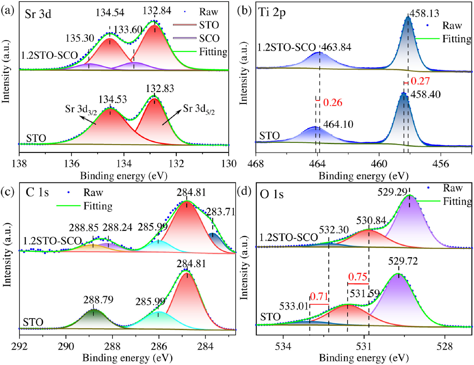
Figure 1.
XPS spectra of the STO and 1.2STO-SCO: Sr 3d (a), Ti 2p (b), C 1s (c), O 1s (d).
One-pot synthesis of SrTiO3-SrCO3 heterojunction with strong interfacial electronic interaction as a novel photocatalyst for water splitting to generate H2
Yige Deng , Song Shu , Ningjie Fang , Ruobing Wang , Yinghao Chu , Zhaobing Liu , Wanglai Cen

With the general recognition of the awareness of carbon neutrality, exploring various kinds of approaches to realize the vision of carbon neutrality has become a global target. The continuous consumption of fossil fuels has resulted in severe environmental issues due to the emission of SO2, NOX, CO2 and so on. Thus, it is highly urgent to develop new energy sources as fossil fuel alternatives to alleviate the environmental and energy pressures [1-3]. Solar energy is a kind of abundant and clean energy, while hydrogen energy has the characteristics of high energy efficiency ratio, clean and recyclable. Both of which were considered to be awfully promising new energy [4-9]. Catalytic technologies such as electrocatalysis and photocatalysis were widely used in environmental and energy fields [10, 11]. The technology of water splitting to generate H2 can transform endless scattered solar energy into highly intensive hydrogen energy. Besides, it has the advantages of mass production, environment friendly, low price, stable performance, easy to obtain and so on [12-14]. In brief, this technology is a promising strategy to achieve carbon neutrality.
In 1972, Fujishima and Honda found that lighting single crystal rutile TiO2 could generate H2 by electrolysis of water, which opened the prelude to converting solar energy into hydrogen energy [15]. So far, various semiconductor materials have been used for water splitting to generate H2, for instance, TiO2, ZnO, SrTiO3, BiVO4, CdS, MnCdS, Ge3N4, ZnXCd1-XS, g-C3N4 [16-24]. Among them, emblematic perovskite oxides of SrTiO3 which shows a Goldschmidt tolerance factor close to 1 have attracted intensive interest due to its stable chemical structure and low concentration of lattice imperfection [25-30]. The first demonstration of SrTiO3 loaded with NiO in photocatalysis was carried out by Domen in 1980 [31]. Recently, Domen's team reported a modified Al-doped SrTiO3 photocatalyst used for overall water splitting, and its external quantum efficiency (EQE) was improved to 96% at a wavelength of 350–360 nm. This record high efficiency means that the potential of SrTiO3 for water splitting to generate H2 is immeasurable [32].
Nevertheless, the majority of the photo-generated charge carriers in SrTiO3 recombined before they reached the surface for chemical reactions. The current modification methods of SrTiO3 mainly included supported deposition cocatalyst, ion doping and constructing semiconductor composites [33]. Constructing semiconductor heterojunction has been confirmed as an effective way to accelerate the transmission and separation of photo-generated carriers for improving photocatalytic efficiency [34, 35]. In this regard, a variety of semiconductors, for instance, CdS, TiO2, CdSe, BiVO4, g-C3N4, rGO, Mo2C, have been coupled with SrTiO3 to form heterojunction for the research of the water splitting to generate H2 [36-42]. Nevertheless, most of these heterojunctions were prepared via complex and energy-intensive processes and their photocatalytic H2 evolution rates are still low. Photocatalyst synthesized by facile method can not realize the tight contact in most cases, so the separation efficiency of photo-generated carriers is low.
The formation of SrCO3 impurity is inevitable during the preparation process of SrTiO3 by the hydrothermal method. Although SrCO3 is regarded as a by-product in the synthesis of SrTiO3, SrCO3 was repeatedly compounded with TiO2 as a photocatalyst [43-45]. Moreover, SrTiO3-SrCO3 heterojunction composite photocatalyst has also been reported for photocatalytic removal of NOX, photocatalytic degradation of methylene blue dye and tetracycline hydrochloride, photocatalytic oxidation of methane [46-49]. In this study, we in-situ synthesized a series of SrTiO3-SrCO3 heterojunction photocatalyst by a one-pot hydrothermal method. This green and facile preparation method has the significance of environmental friendliness [50]. This heterojunction structure with strong interfacial electronic interaction promotes the transmission and separation of photo-generated carriers. With Pt as co-catalyst, the optimized sample of SrTiO3-SrCO3 exhibits an excellent photocatalytic H2 evolution rate as high as 3.62 mmol h−1g−1, which is 20.1 times higher than that of pristine SrTiO3. In addition, the material shows excellent long-term illumination stability, which indicates that the material has great significance in the synthesis of hydrogen energy for long-term use. The detailed experimental content is given in Supporting information.
The crystal structure and phase of the samples are analyzed by X-ray powder diffraction (XRD). As shown in Fig. S2a (Supporting information), all the samples show good crystallinity. The diffraction peaks of the sample washed with acetic acid can all correspond to the SrTiO3 (JCPDS No. 35–0734). And there is no extra diffraction peak, indicating that the STO is pure phase. With the change of Sr to Ti molar ratio, new diffraction peaks can be observed in all XSTO-SCO (X represents the molar ratio of Sr to Ti) samples, and the intensity of these diffraction peaks increases with the increase of the Sr amount. These emerging diffraction peaks are attributed to SrCO3 (JCPDS No. 05–0418), indicating that SrCO3 is present in XSTO-SCO. Besides, the positions of all diffraction peaks are not shifted, indicating that SrCO3 and SrTiO3 are two independent crystal phases, and no lattice distortion occurs between them. The characteristic peak strength of the STO decreases to a certain extent, and the half-peak width increases, indicating that the crystallinity becomes worse, which may be due to the particle size of the STO decreasing during the acetic acid washing process.
The main reason for the formation of SrCO3 is that the precursor of Sr can not only react with Ti source to produce SrTiO3, but also react with CO2 in the air to produce SrCO3 under alkaline conditions, and the more Sr source, the more SrCO3 can be generated. Therefore, SrTiO3-SrCO3 heterojunction photocatalysts with different SrCO3 content can be synthesized by adjusting the molar ratio of Sr to Ti.
The surface morphologies of the samples are investigated by scanning electron microscopy (SEM) and the results are shown in Figs. S3 and S4 (Supporting information). As shown in Figs. S3a and b, the particle dispersion of the STO is good, while the surface of the STO is relative rough. What is more, the particles show spherical-like morphology and their sizes are not uniform. There are small spheres attached to the large ones. Its unique "golf-like" structure of high-surface area and defect-rich surface can provide more adsorption sites [51]. As shown in Figs. S3c and d, both nanospheres and nanorods can be observed for 1.2STO-SCO sample. According to the XRD results, this can be attributed to the generated SrCO3. The average diameters of the STO and the 1.2STO-SCO are 334.5 and 209.6 nm, respectively. This may be due to the small equivalent grain size of the slender rod-shaped particles in the laser particle size analyzer [52]. Similarly, smaller particle size contributes to the enhancement of photocatalytic activity of samples [53].
To further verify the hypothesis, we performed TEM observation on the samples. As shown in Figs. S5a-c (Supporting information), the morphology of the samples observed by TEM is consistent with SEM results. Bright dots corresponding to the "pits" on golf-like microspheres could be found [51]. Two different lattice fringes with d values of 0.277 and 0.352 nm can be observed by HRTEM (Figs. S4d-f), which corresponds to the crystal plane of SrTiO3(110) and SrCO3(111), respectively. This further proves that both the large and small spheres are SrTiO3 and the rods are SrCO3. Moreover, the crystals are closely connected, which indicates that the heterojunction with close interface can be successfully synthesized by a facile one-pot hydrothermal method.
The 1.2STO-SCO sample is scanned by SEM-EDS. Figs. S2b-d (Supporting information) illustrate the element composition on the sample surface, which are consistent with the theory values, and the semi-quantitative results are shown in Table S1 (Supporting information). In Figs. S2e-h (Supporting information), the EDS element mapping of 1.2STO-SCO displays the homogeneous distribution of Sr, Ti, O and C elements in the sample.
X-ray photoelectron spectroscopy (XPS) is further used to investigate the surface chemical states of the STO and 1.2STO-SCO. Fig. S6 (Supporting information) shows the XPS full-scan spectra of the samples. Both the surface of samples contained Sr, Ti, O, C elements, which is consistent with the results of XRD and EDS characterization. The C 1s peak at 284.8 eV is used as a standard correction for charge effects in non-conductive samples [54].
The XPS high-resolution spectra of the samples prove the influence of SrCO3 on the properties of SrTiO3. Fig. 1a shows the Sr 3d XPS characteristic peaks of the samples. Sr 3d is divided into two peaks of Sr 3d5/2 and Sr 3d3/2, with an interval of 1.7 eV, indicating that Sr exists in the form of Sr2+ in the sample [55]. The Sr 3d spectrum of the 1.2STO-SCO is fitted into two peaks, meaning two forms of Sr2+ are found. The binding energies of 132.84 eV and 134.54 eV belong to SrTiO3, while the binding energies of 133.60 eV and 135.30 eV are attributed to SrCO3 [48]. Fig. 1b shows the Ti 2p XPS characteristic peaks of the samples, and Ti 2p is divided into two peaks, Ti 2p1/2 and Ti 2p3/2, with an interval of 5.7 eV, indicating that Ti exists in the form of Ti4+ [56]. Moreover, the Ti 2p binding energy of the 1.2STO-SCO moves towards the lower value, this may be due to the formation of heterojunction between SrTiO3 and SrCO3, and there is a strong chemical bond between them [57].
To further illustrate the influence of heterojunction, the C 1s spectra of the samples are analyzed, as shown in Fig. 1c. The introduction of SrCO3 will bring some new C 1s signals, but due to the small amount, the signal is weak. So, the signal intensity of the 1.2STO-SCO fluctuates greatly. The C 1s spectra of the STO is fitted, and the peaks are located at 284.81 eV, 285.99 eV and 288.79 eV, respectively, which are attributed to C—C bond (conductive adhesive pollution), C—O—C bond (atmospheric pollution) and O—C=O bond (organic carbonyl), respectively [58]. Three new peaks are discovered at 283.71 eV, 288.24 eV and 288.85 eV by fitting the 1.2STO-SCO C 1s spectrum, which are attributed to C—Ti—O bond, C—O—Ti bond and O—C=O bond in SrCO3, respectively [59-62].
The O 1s spectrum of the STO is fitted, as shown in Fig. 1d. The binding energy peaks are located at 529.72 eV, 531.59 eV and 533.01 eV, respectively, belonging to Sr-O-Ti (the lattice oxygen in SrTiO3), O—H bond (water molecules on the sample surface) and O—C=O bond (organic carbonyl), respectively [63, 64]. The O 1s binding energy of the 1.2STO-SCO still moves to the lower value due to the heterojunction, and a new peak emerges at 532.30 eV, which belongs to the O—C=O bond in SrCO3 [62]. And the peak of the carbonyl group is covered by the peak of the carbonate group. All the above XPS results indicate that there is indeed a strong chemical bond interaction between SrTiO3 and SrCO3.
All samples are tested for the activity of water splitting to generate H2 under simulated sunlight irradiation. The specific test steps are shown in Supporting information. The activity results are shown in Figs. 2a-c. Pristine SrTiO3 exhibits a low photocatalytic H2 evolution rate of only 0.18 mmol h−1g−1 due to the wide band gap and the rapid recombination of photo-generated carriers [65, 66]. However, when an applicable amount of SrCO3 is combined with SrTiO3, the photocatalytic H2 evolution rate of the samples is greatly improved. The order of the rates are as follows: 3.62 mmol h−1g−1 (1.2STO-SCO) > 2.93 mmol h−1g−1 (1.0STO-SCO) > 2.36 mmol h−1g−1 (1.4STO-SCO) > 1.92 mmol h−1g−1 (1.6STO-SCO) > 1.02 mmol h−1g−1 (0.8STO-SCO). The photocatalytic H2 evolution rate of the 1.2STO-SCO is 20.1 times higher than that of pristine SrTiO3.
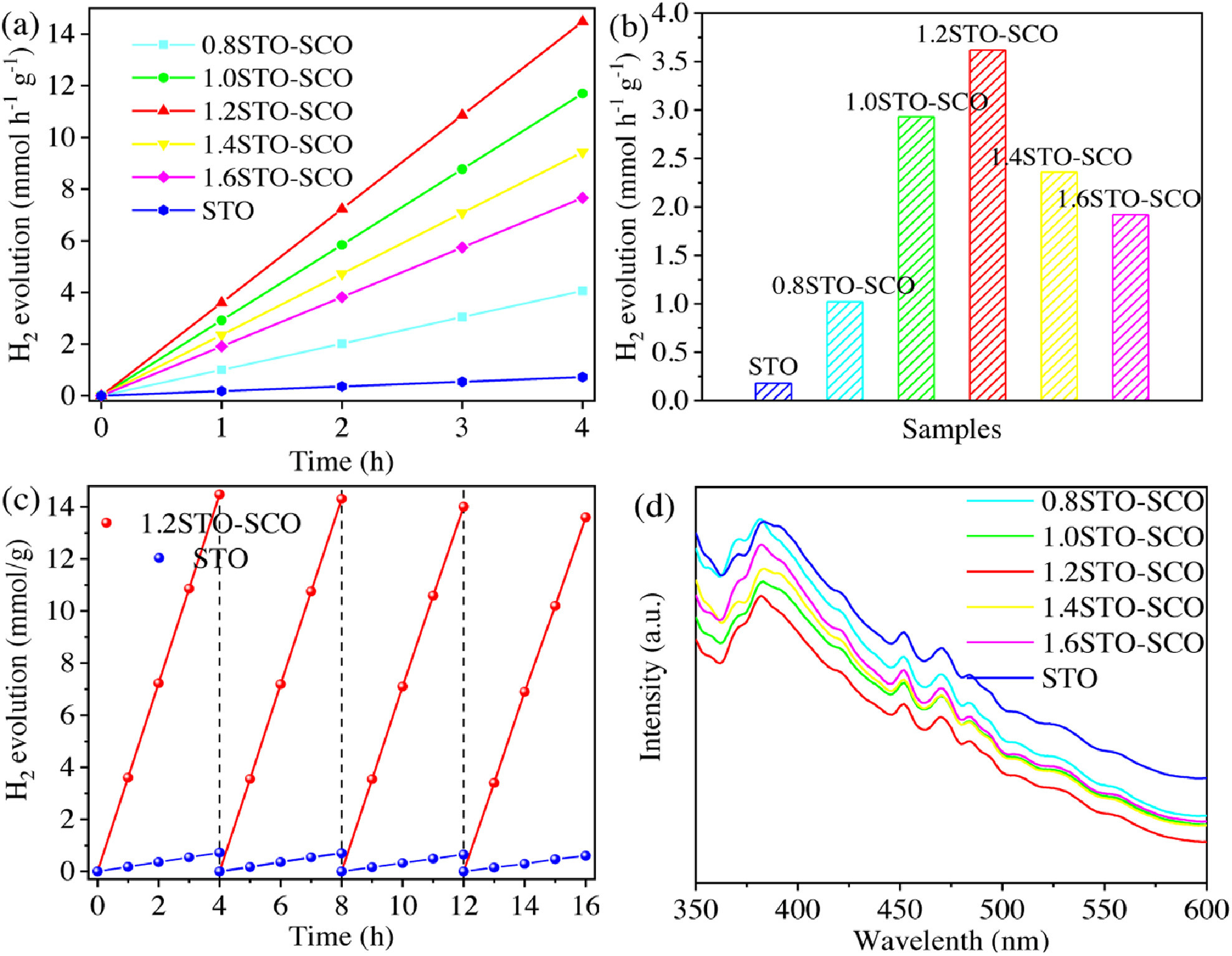
As shown in Table S2 (Supporting information), 1.2STO-SCO has better performance of photocatalytic hydrogen production compared with other SrTiO3 based photocatalysts reported in the literature. With the increase of the input Sr source, that is, the content of SrCO3 in the samples increases, the photocatalytic performance of the samples first increases and then decreases. The possible reason is that an appropriate amount of SrCO3 can form a close heterostructure with SrTiO3, thus promoting the effective transmission and separation of photo-generated carriers. When the load amount of SrCO3 is low, the heterojunction interface is small, the transmission and separation efficiency of photo-generated carriers are weak, and the active sites used for hydrogen production reaction are less. However, when the load amount of SrCO3 is excessive, SrCO3 overcovers the surface of SrTiO3, which not only covers the active sites of SrTiO3, but also becomes the new recombination center of photo-generated carriers, thus reducing the activity. In addition, the band gap of SrCO3 is too large. If the SrCO3 is overloaded in the sample, its light absorption capacity will be weakened. This indicates that SrTiO3 and proper amount of SrCO3 have a synergistic effect in the photocatalytic hydrogen production reaction [67].
The apparent quantum efficiency (AQE) of the 1.2STO-SCO is obtained by measuring the amount of hydrogen produced under the monochromatic light irradiation of 313 nm (±5 nm). The average hydrogen production in 1 h is 43.69 µmol. As a consequence, the 1.2STO-SCO has a high surface light quantum efficiency of 21.73%.
Moreover, the stability of the STO and 1.2STO-SCO is evaluated after 4 cycles, with a total testing time of 16 h. As shown in Fig. 2c, the photocatalytic H2 evolution amount of the 1.2STO-SCO has hardly decreased, indicating that it has excellent stability and photocorrosion resistance. In addition, the photocatalytic H2 evolution rate of the 1.2STO-SCO in each cycle is significantly higher than that of the STO, which further indicates that SrCO3 addition contributes to improving the photocatalytic activity of SrTiO3.
The light absorption capacity of the samples is analyzed by UV–vis diffuse reflectance spectra scanning, as shown in Fig. S7a (Supporting information). The absorption band edge of all samples is about 380 nm, which appears apparent light absorption in the ultraviolet region. Compared with pristine SrTiO3, the absorption band edge of the composite photocatalyst supported by SrCO3 has a slight blue shift. This is due to that the band gap of SrCO3 is larger than that of SrTiO3, hence, the presence of SrCO3 in the samples will weaken the light absorption capacity of pristine SrTiO3 [68, 69].
In addition, the Tauc plot is obtained by the conversion of UV–vis DRS to estimate the band gap values of the samples, as shown in Fig. S7b (Supporting information). The estimated band gap (Eg) values of the STO and 1.2STO-SCO are 3.28 eV and 3.34 eV, respectively, which are consistent with the results of the absorption band edge and the values in the literature [41, 68]. The band gap of the 1.2STO-SCO is slightly larger than that of the STO, indicating that the presence of SrCO3 is not conducive to the light absorption. Thus, the band gap is not the critical factor affecting the photocatalytic activity of the composite photocatalyst [46].
The process of photo-generated carrier transmission, separation and recombination of the samples are analyzed by photoluminescence spectra at the excitation wavelength of 325 nm. The signal intensity in PL is the fluorescence generated by electron transition and then carrier recombination in the sample, so the peak intensity of PL can reflect the separation efficiency of carriers [70]. As shown in Fig. 2d, the PL signal of the 1.2STO-SCO is much weaker than that of the STO, in other words, the addition of SrCO3 can greatly quench the fluorescence emission effect of SrTiO3 [71].
SrCO3 has a wide band gap, so it cannot be excited by light and cannot produce electrons. But the separation efficiency of photo-generated carrier of composite photocatalyst is improved. The composite photocatalyst with strong interfacial electronic interaction has excellent photocatalytic performance [72]. In conclusion, the results of UV–vis DRS and PL indicate that in the photocatalytic hydrogen production reaction, the formation of SrTiO3-SrCO3 heterojunction mainly breaks through the limitations of dynamics rather than thermodynamics.
The photocatalytic hydrogen production process of the composite photocatalyst is further analyzed by photochemical tests, including the photocurrent density curve (PC) and electrochemical impedance spectroscopy (EIS).
Fig. 3a shows the change curve of the photocurrent density with time of the samples in 0.5 mol/L Na2SO4 solution under cyclic simulation of sunlight irradiation. The signal in PC is generated by the transfer of photo-generated electrons from the sample to the conductive glass, so the peak intensity of PC can measure the carrier concentration of the sample under illumination [73]. The photocurrent density of the 1.2STO-SCO (~1.31 µA/cm2) is significantly higher than that of the STO (~0.35 µA/cm2). The former is about 3.74 times higher than the latter. This indicates that under illumination, SrCO3 can effectively transfer the photo-generated carriers of SrTiO3, so it can be separated effectively.
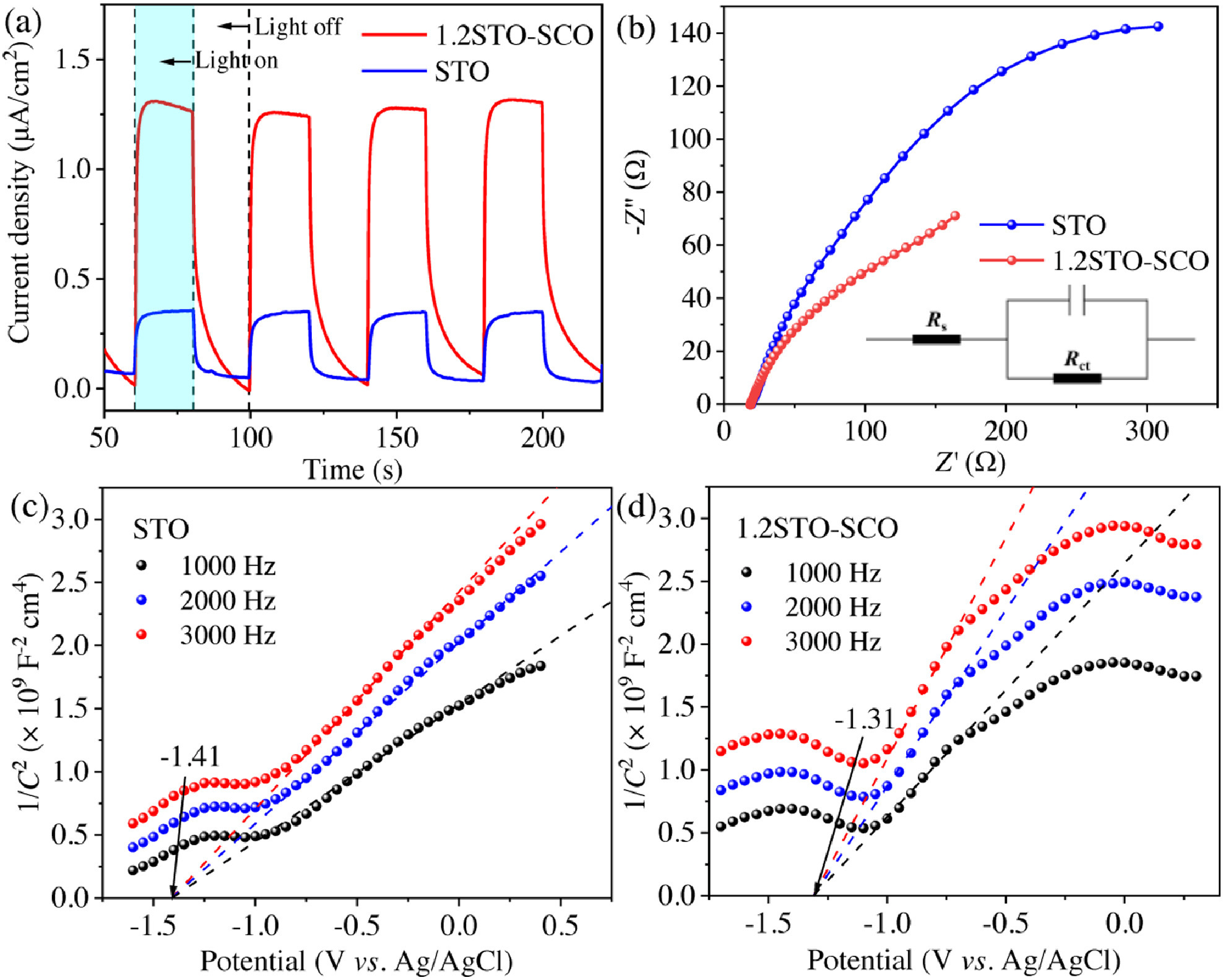
The variation of the 1.2STO-SCO relative to the STO's internal resistance is further investigated by electrochemical impedance spectroscopy (EIS), as shown in Fig. 3b. The analysis of Nyquist electrochemical impedance spectra shows that the arc radius of the 1.2STO-SCO fitting curve is smaller than that of STO, which indicates that the charge transfer becomes easier. Therefore, the separation of photo-generated carriers is easier in 1.2STO-SCO. This means that the recombination of SrCO3 will reduce the electron transfer resistance between SrTiO3 and the interface, thus, accelerating the transmission and separation of photo-generated carriers. The final EIS fitting results are shown in Table S3 (Supporting information).
The excellent photocatalytic hydrogen production performance of the 1.2STO-SCO is further explained by Mott-Schottky (M-S) curves test at 1 kHz, 2 kHz and 3 kHz, respectively. The results are illustrated in Figs. 3c and d. The slope values of the fitting curve of the STO and 1.2STO-SCO are positive. It means that SrTiO3 has the characteristics of n-type semiconductor. According to the literature, SrCO3 is a n-type semiconductor too. So it can be judged that SrTiO3-SrCO3 is "n-n" type semiconductor heterojunction [74, 75].
The flat band potential (EFB) of the STO and 1.2STO-SCO are −1.41 eV and −1.31 eV (vs. Ag/AgCl), respectively, and are about −1.21 eV and −1.11 eV (vs. NHE). According to Eqs. 1 and 2, the conduction band potentials (ECB) of the STO and 1.2STO-SCO are −1.31 eV and −1.21 eV (vs. NHE), respectively. The valence band potential (EVB) of the STO and 1.2STO-SCO are 1.97 eV and 2.13 eV (vs. NHE), respectively, where Eg are obtained by UV–vis DRS [76-78]. Finally, the positions of valence conduction bands of the STO and 1.2STO-SCO are shown in Table S4 (Supporting information).
|
|
(1) |
|
|
(2) |
In order to quantitatively study the effect of the molar ratio of SrCO3 to SrTiO3 on the activity of the samples, we prepared two more groups of samples with different Sr to Ti ratios, named 1.1STO-SCO and 1.5STO-SCO. XPS was carried out to analyze the element content. As shown in Figs. S8a-g (Supporting information), the characteristic peaks of Sr 3d XPS are fitted. According to the peak areas of the sub peaks, the ratio of two forms of Sr2+ is calculated, and the molar ratio of SrCO3 and SrTiO3 on the sample surface is determined quantitatively. The SrCO3 content on the surface of the samples is linearly fitted with the photocatalytic H2 evolution rate of the sample. The fitting result is shown in Fig. S8h (Supporting information), with R2 = 0.99, indicating good linearity. It can be concluded that the content of SrCO3 in the sample is the critical factor to determine the photocatalytic hydrogen production activity of the sample. The photocatalytic H2 evolution rate of the sample first increase and then decrease with the increase content of SrCO3 in the sample. The content of SrCO3 in the 1.2STO-SCO is 15.50% and the photocatalytic H2 evolution rate of this sample is the highest.
The composition in the bulk phase of the samples is analyzed by inductively coupled plasma optical emission spectrometer (ICP-OES). Fig. S9a (Supporting information) shows the molar ratio of Sr to Ti. As shown in Fig. S9b (Supporting information), we found that with the increase content of SrCO3, the photocatalytic hydrogen production activity of the sample first increased and then decreased, but the fitting linearity is poor. The SrCO3 content in the samples is shown in Table S5 (Supporting information). Compared with the Sr 3d fitting results in XPS, it is further confirmed that the hydrogen production reaction is carried out on the surface rather than in the bulk phase.
In order to further confirm the interfacial electronic interaction of the SrTiO3/SrCO3 heterojunction, we calculated its variation of electronic density.
|
|
(3) |
In Eq. 3, ρ(SrTiO3/SrCO3) is the electron density of the SrTiO3/SrCO3 heterojunction, while ρ(SrTiO3) and ρ(SrCO3) are the unperturbed electron densities of the SrTiO3 (110) and SrCO3 (111), respectively. As shown in Fig. 4a, the isosurface value is 0.003 e/Å3. The cyan and yellow regions represent the electron depletion and accumulation, respectively. The Sr, Ti, C and O atoms are represented as green, blue, brown and red, respectively. A strong region of charge accumulation is found on the SrCO3, and the region of charge depletion is found on the Sr, Ti and O atoms of SrTiO3. Fig. 4b plots the planar averaged charge density. The increase and decrease of the value represent electron accumulation and depletion, respectively. In conclusion, the electrons transfer from the SrTiO3 to SrCO3. So this heterojunction has strong interfacial electronic interaction, which is driven by the band arrangement [79].
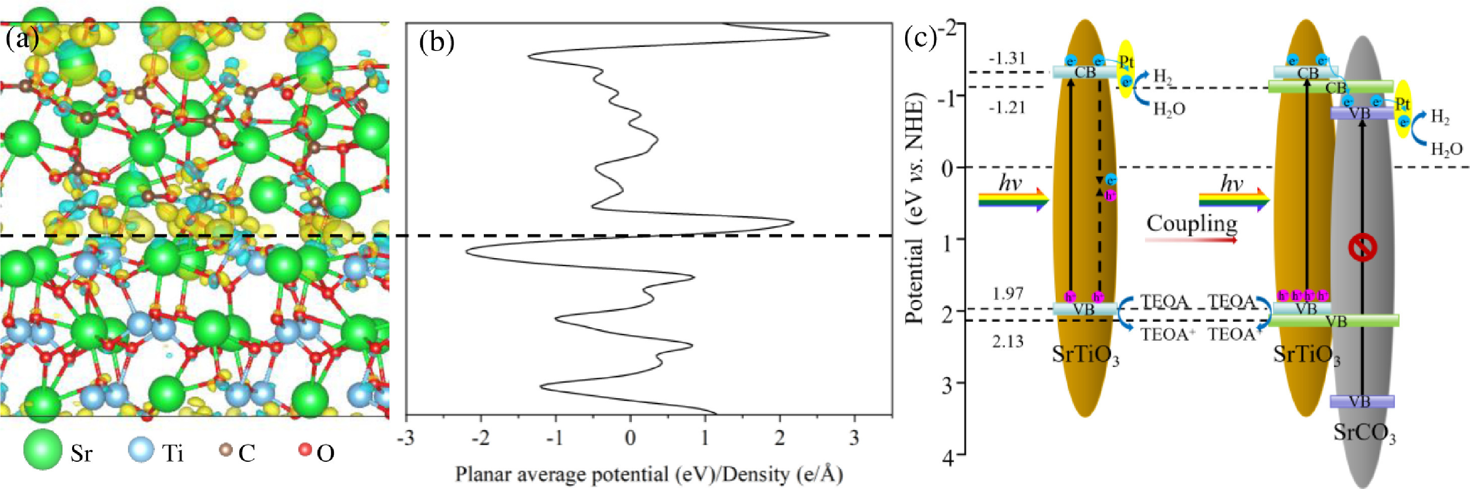
Based on the above analysis, a feasible photocatalytic mechanism for the SrCO3-SrTiO3 heterojunction photocatalyst is illustrated in Fig. 4c. Under simulated sunlight irradiation, SrTiO3 is excited by light to produce photo-generated electrons and holes. Regrettably, the photo-generated carriers produced by pristine SrTiO3 are easy to recombine, resulting in its low photocatalytic activity. Therefore, in this study, we coupled SrTiO3 and SrCO3 to form the type II heterojunction with a tight structure. Based on the internal electric field at the interface, the electrons are rapidly transferred from SrTiO3 at the high conductivity band to SrCO3 at the low conductivity band. And then the electrons immediately transferred to Pt particles to reduce H+ and generate H2 [80, 81]. At the same time, the holes react with TEOA in solution rapidly in the valence band of SrTiO3, thus promoting the transmission and separation of photo-generated carriers in space, and finally enhancing the photocatalytic activity of the catalyst.
In summary, a novel SrTiO3-SrCO3 heterojunction photocatalyst with strong interfacial electronic interaction was synthesized by a facile one-pot hydrothermal method. The photocatalytic H2 evolution rate of the 1.2STO-SCO is as high as 3.62 mmol h−1g−1, which is 20.1 times higher than that of pristine SrTiO3. The apparent quantum efficiency of the 1.2STO-SCO is as high as 21.73%, and it is stable under long-term irradiation. Through various characterization, it has been confirmed that SrTiO3 and SrCO3 can contact closely with each other to form heterojunction, thus promoting the transmission and separation of photo-generated carriers. Therefore, more photo-generated electrons involved in the production of H2, and the photocatalytic activity of SrTiO3 can be improved. This work contributes to the design and preparation of more SrTiO3-based heterojunction photocatalysts for water splitting to generate H2.
The authors report no declarations of interest.
This work was supported by the Key Research Projects of Science and Technology Department of Sichuan Province (No. 2020YJ0260).
Supplementary material associated with this article can be found, in the online version, at doi:
M. Gratzel, Nature 414 (2001) 338–344. doi: 10.1038/35104607
J.A. Turner, Science 305 (2004) 972–974. doi: 10.1126/science.1103197
S. Dahiya, S. Chatterjee, O. Sarkar, S.V. Mohan, Bioresour. Technol. 321 (2021) 124354. doi: 10.1016/j.biortech.2020.124354
J.Y. Hu, C.Y. Zhai, M.S. Zhu, Chin. Chem. Lett. 32 (2021) 1348–1358. doi: 10.1016/j.cclet.2020.09.049
J.H. Carey, J. Lawrence, H.M. Tosine, Bull. Environ. Contam. Toxicol. 16 (1976) 697–701. doi: 10.1007/BF01685575
P. Langereux, Nature 260 (1976) 477-477.
K. Maeda, K. Domen, J. Phys. Chem. Lett. 1 (2010) 2655–2661. doi: 10.1021/jz1007966
M.G. Walter, E.L. Warren, J.R. McKone, et al., Chem Rev. 110 (2010) 6446–6473. doi: 10.1021/cr1002326
M.S. Dresselhaus, I.L. Thomas, Nature 414 (2001) 332–337. doi: 10.1038/35104599
A.D. Tjandra, J. Huang, Chin. Chem. Lett. 29 (2018) 734–746. doi: 10.1016/j.cclet.2018.03.017
D. Hao, Y. Liu, S.Y. Gao, et al., Mater. Today 46 (2021) 212–233. doi: 10.1016/j.mattod.2021.01.029
J.Z. Zhang, MRS Bull. 36 (2011) 48–55. doi: 10.1557/mrs.2010.9
Z.L. Zhao, P. Wang, X.L. Xu, M. Sheves, Y.D. Jin, J. Am. Chem. Soc. 137 (2015) 2840–2843. doi: 10.1021/jacs.5b00200
Z. Wang, C. Li, K. Domen, Chem. Soc. Rev. 48 (2019) 2109–2125. doi: 10.1039/C8CS00542G
A. Fujishima, K. Honda, Nature 238 (1972) 37–38. doi: 10.1038/238037a0
L. Guo, Z. Yang, K. Marcus, et al., Energy Environ. Sci. 11 (2017) 106–114.
Y.J. Liu, H.X. Liu, H.M. Zhou, T.D. Li, L.N. Zhang, Appl. Surf. Sci. 466 (2019) 133–140. doi: 10.1016/j.apsusc.2018.10.027
H.L. Hou, F.M. Gao L. Wang, X.F. Yang, W.Y. Yang, J. Mater. Chem. C 7 (2019) 7858–7864. doi: 10.1039/C9TC02480H
S. Wang, B.C. Zhu, M.J. Liu, et al., Appl. Catal. B 243 (2019) 19–26. doi: 10.1016/j.apcatb.2018.10.019
J. Sato, N. Saito, Y. Yamada, et al., J. Am. Chem. Soc. 127 (2005) 4150–4151. doi: 10.1021/ja042973v
X.X. Zhao, J.R. Feng, J. Liu, et al., Angew. Chem. Int. Ed. 57 (2018) 9790–9794. doi: 10.1002/anie.201805425
J.W. Fu, Q.L. Xu. J.X. Low, J.G. Yu, Appl. Catal. B 243 (2019) 556–565. doi: 10.1016/j.apcatb.2018.11.011
Y.Z. Wei, J.Y. Wang, R.B. Yu, J.W. Wan, D. Wang, Angew. Chem. Int. Ed. 58 (2019) 1422–1426. doi: 10.1002/anie.201812364
N.J. Fang, X.C. Song, M.Y. Zhang, Y.H. Chu, Int. J. 46 (2021) 30382–30392.
M.C. Carotta, G. Martinelli, Y. Sadaoka, P. Nunziante, E. Traversa, Sens. Actuat. B: Chem. 48 (1998) 270–276. doi: 10.1016/S0925-4005(98)00011-2
W. Yude, X.D. Sun, Y.F. Li, et al., Solid-State Electron. 44 (2000) 2009–2014. doi: 10.1016/S0038-1101(00)00151-9
X.H. Wu, Y.D. Wang, Y.F. Li, Z.L. Zhou, X.H. Wu, Mater. Chem. Phys. 77 (2003) 588–593. doi: 10.1016/S0254-0584(02)00116-5
H. Tanaka, M. Misono, Curr. Opin. Solid State Mater. Sci. 5 (2001) 381–387. doi: 10.1016/S1359-0286(01)00035-3
S.Y. Fang, Y.H. Hu, Int. J. Energy Res. 43 (2019) 1082–1098. doi: 10.1002/er.4259
M. Itoh, H. Taniguchi, Ferroelectrics 369 (2008) 127–132. doi: 10.1080/00150190802377918
K. Domen, S. Naito, M. Soma, T. Onishi, K. Tamaru, J. Chem. Soc., Chem. Commun. 12 (1980) 543–544.
T. Takata, J. Jiang, Y. Sakata, et al., Nature 581 (2020) 411–414. doi: 10.1038/s41586-020-2278-9
Q. Wang, K. Domen, Chem. Rev. 120 (2020) 919–985. doi: 10.1021/acs.chemrev.9b00201
S. Bai, J. Jiang, Q. Zhang, Y.J. Xiong, Chem. Soc. Rev. 44 (2015) 2893–2939. doi: 10.1039/C5CS00064E
Y.P. Yuan, L.W. Ruan, J. Barber, S.C.J. Loo, C. Xue, Energy Environ. Sci. 7 (2014) 3934–3951. doi: 10.1039/C4EE02914C
X.L. Yin, L.L. Li, D.C. Li, et al., J. Colloid Interface Sci. 536 (2019) 694–700. doi: 10.1016/j.jcis.2018.10.097
S.T. Han, L.S. Yu, H.W. Zhang, et al., ChemCatChem 11 (2019) 6203–6207. doi: 10.1002/cctc.201901399
J.S. Han, F.X. Dai, Y. Liu, et al., Appl. Surf. Sci. 467 (2019) 1033–1039.
J.M. Wang, M.T. Kuo, P. Zeng, et al., Appl. Catal. B 279 (2020) 119377. doi: 10.1016/j.apcatb.2020.119377
J.Q. Pan, Y.Y. Liu, O. Wei, et al., Renew. Energy 161 (2020) 340–349. doi: 10.1016/j.renene.2020.07.097
G.L. He, Y.H. Zhong, M.J. Chen, et al., J. Mol. Catal. A: Chem. 423 (2016) 70–76. doi: 10.1016/j.molcata.2016.05.025
S.S. Yi X.Z. Yue, R.W. Wang, Z.T. Zhang, S.L. Qiu, Nano Energy 47 (2018) 463–473. doi: 10.1016/j.nanoen.2018.03.014
M.J. Zhai, Y. Liu, J. Huang, et al., J. Therm. Spray Technol. 29 (2020) 1172–1182. doi: 10.1007/s11666-020-01022-9
J.P. Jin, S.T. Chen, J.M. Wang, C. Chen, T.Y. Peng, Appl. Surf. Sci. 476 (2019) 937–947. doi: 10.1016/j.apsusc.2019.01.176
J. Fu, G.Z. Kyzas, Z.Q. Cai, et al., Chem. Eng. J. 335 (2018) 290–300. doi: 10.1016/j.cej.2017.10.163
S. Jin, G.H. Dong, J.M. Luo, F.Y. Ma, C.Y. Wang, Appl. Catal. B 227 (2018) 24–34. doi: 10.1016/j.apcatb.2018.01.020
A. Marquez-Herrera, V.M. Ovando-Medina, B.E. Castillo-Reyes, et al., J. Nanopart. Res. 16 (2014) 2804. doi: 10.1007/s11051-014-2804-5
Y.N. Chen, Z. Peng, Y.P. Li, et al., J. Mater. Sci. 56 (2021) 4356–4365. doi: 10.1007/s10853-020-05529-y
X.Y. Pan, X.X. Chen, Z.G. Yi, Phys. Chem. Chem. Phys. 18 (2016) 31400–31409. doi: 10.1039/C6CP04604E
D. Hao, J.W. Ren, Y. Wang, et al., Energy Mater. Adv. 2021 (2021) 9761263.
M. Zhou, J.W. Chen, Y.K. Zhang, et al., J. Alloys Compd. 817 (2020) 152796. doi: 10.1016/j.jallcom.2019.152796
M. Serkis-Rodzen, M. Spirkova, P. Matejicek, M. Stepanek, Prog. Org. Coat. 106 (2017) 119–127. doi: 10.1016/j.porgcoat.2017.03.003
J.Q. Wang, X. Wang, B. Liu, X.H. Li, M.H. Cao, Mater. Lett. 152 (2015) 131–134. doi: 10.1016/j.matlet.2015.03.104
F. Yu, L.C. Wang, Q.J. Xing, et al., Chin. Chem. Lett. 31 (2020) 1648–1653. doi: 10.1016/j.cclet.2019.08.020
J.J. Kong, Z.B. Rui, H.B. Ji, Ind. Eng. Chem. Res. 55 (2016) 11923–11930. doi: 10.1021/acs.iecr.6b03270
H.Q. Tan, Z. Zhao, W.B. Zhu, et al., ACS Appl. Mater. Interfaces. 6 (2014) 19184–19190. doi: 10.1021/am5051907
S.X. Ouyang, H. Tong, N. Umezawa, et al., J. Am. Chem. Soc. 134 (2012) 1974–1977. doi: 10.1021/ja210610h
S.S. Yi X.Z. Yue, R.W. Wang, Z.T. Zhang, S.L. Qiu, Nanoscale 8 (2016) 17516–17523. doi: 10.1039/C6NR06620H
I. Tamiolakis, D. Liu, F.X. Xiao, et al., Appl. Catal. B 236 (2018) 338–347. doi: 10.1016/j.apcatb.2018.05.036
E. Lewin, P.O.A. Persson, M. Lattemann, et al., Surf. Coat. Technol. 202 (2008) 3563–3570. doi: 10.1016/j.surfcoat.2007.12.038
Y. Zhang, Z.Y. Zhao, J.R. Chen, et al., Appl. Catal. B 165 (2015) 715–722. doi: 10.1016/j.apcatb.2014.10.063
X.X. Fan, Y. Wang, X.Y. Chen, et al., Chem. Mater. 22 (2010) 1276–1278. doi: 10.1021/cm903303v
U. Sulaeman, Y. Shu, T. Sato, Adv. Nanopart. 2 (2013) 6–10. doi: 10.4236/anp.2013.21002
Y.O. Wang, M.K. Bayazit, S.J.A. Moniz, et al., Energy Environ. Sci. 10 (2017) 1643–1651. doi: 10.1039/C7EE01109A
H. Kato, A. Kudo, J. Phys. Chem. B 106 (2002) 5029–5034. doi: 10.1021/jp0255482
J.W. Ng, S.P. Xu, X.W. Zhang, H.Y. Yang, D.D. Sun, Adv. Funct. Mater. 20 (2010) 4287–4294. doi: 10.1002/adfm.201000931
F. Wang, Z.G. Kan, F. Cao, et al., Chin. Chem. Lett. 29 (2018) 1417–1420. doi: 10.1016/j.cclet.2017.11.030
J.I. Fujisawa, T. Eda, M. Hanaya, Chem. Phys. Lett. 685 (2017) 23–26. doi: 10.1016/j.cplett.2017.07.031
H. Wang, Y.J. Sun, G.M. Jiang, et al., Environ. Sci. Technol. 52 (2018) 1479–1487. doi: 10.1021/acs.est.7b05457
M. Anpo, M. Che, Adv. Catal. 44 (1999) 119–257.
D. Hao, C.W. Liu, X.X. Xu, et al., New J. Chem. 44 (2020) 20651–20658. doi: 10.1039/D0NJ04068A
M.M. Krzmanc, N. Daneu, A. Contala, et al., ACS Appl. Mater. Interfaces. 13 (2021) 370–381. doi: 10.1021/acsami.0c16253
M.F. Shao, F.Y. Ning, M. Wei, D.G. Evans, X. Duan, Adv. Funct. Mater. 24 (2014) 580–586. doi: 10.1002/adfm.201301889
J. Ke, J. Liu, H.Q. Sun, et al., Appl. Catal. B 200 (2017) 47–55. doi: 10.1016/j.apcatb.2016.06.071
X. Xiao, S.H. Tu, M.L. Lu, et al., Appl. Catal. B 198 (2016) 124–132. doi: 10.1016/j.apcatb.2016.05.042
Y.F. Chen, L.L. Tan, J.M. Liu, et al., Appl. Catal. B 206 (2017) 426–433. doi: 10.1016/j.apcatb.2017.01.040
J. He, J.Q. Wang, Y.J. Chen, et al., Chem. Commun. 50 (2014) 7063–7066. doi: 10.1039/C4CC01086H
X.D. Wang, J.L. Xie, C.M. Li, J. Mater. Chem. A 3 (2015) 1235–1242. doi: 10.1039/C4TA05846A
Y.D. Luo, B. Deng, Y. Pu, et al., Appl. Catal. B 247 (2019) 1–9. doi: 10.1016/j.apcatb.2019.01.089
M.Y. Zhang, N.J. Fang, X.C. Song, et al., ACS Omega 5 (2020) 32715–32723. doi: 10.1021/acsomega.0c05106
L.L. Deng, N.J. Fang, S.L. Wu, et al., J. Colloid Interface Sci. 608 (2022) 2730–2739. doi: 10.1016/j.jcis.2021.10.190

Figure 1 XPS spectra of the STO and 1.2STO-SCO: Sr 3d (a), Ti 2p (b), C 1s (c), O 1s (d).

Figure 2 (a) Photocatalytic H2 evolution curve of samples. (b) Photocatalytic H2 evolution rate of samples. (c) Cycling runs of the STO and 1.2STO-SCO. (d) Photoluminescence spectrum of the samples.

Figure 3 The change curve of the photocurrent density with time of the STO and 1.2STO-SCO (a). Nyquist electrochemical impedance spectra of the STO and 1.2STO-SCO (b). Mott-Schottky plots of the STO (c) and 1.2STO-SCO (d).

 扫一扫看文章

扫一扫关注我们
 DownLoad:
 下载:
下载:
