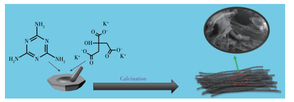
Scheme 1.
Schematic illustration of the synthetic process of NPCF

In today′s world, energy price fluctuations caused by regional wars, political instability, and the potential depletion of traditional fossil fuels have driven people to continuously develop sustainable energy and have made numerous research results, such as solar energy, wind energy, and hydroelectric power[1-3]. As these energy sources were further studied, a variety of shortcomings were discovered, including the inefficiency of solar power generation, as well as the ecological and social destruction of hydroelectric dams and wind farms. In addition, the devices for storing these energy sources also remain some problems. The main issue is that the generated energy must be stored using cheap, efficient, and safe equipment, otherwise, the cost of energy will further increase. To cope with the increasingly serious energy problem, the development of advanced energy storage materials is effective and urgent[4].
The current mainstream energy storage devices, lithium-ion batteries and supercapacitors are the two kinds of energy storage configurations that people put the most effort into. Lithium-ion batteries have a high energy density, but their shortcomings in power density and cycle life make their application a long way off. At the same time, supercapacitors have great advantages in power density and cycle life. Therefore, lithium-ion hybrid capacitors, which combine the advantages of lithium-ion batteries and supercapacitors, are attracted much attention. However, due to the uneven distribution of lithium resources and the scarcity of lithium resources, the cost of lithium-ion hybrid capacitors keeps rising, so it is urgent to develop alternatives to replace lithium[5-6]. Sodium and lithium belong to the same group of elements, and they are all alkali metals with the same electronegativity[7-8]. In addition, research on sodium-ion energy storage materials started as early as the 1970s[7]. After decades of research and development, the anode materials for sodium ion capacitors (SICs) have been centered on carbon-based materials, two-dimensional inorganic compounds, titanium, niobium anode material, and some converted anode materials. Among them, carbon-based materials are the most promising anodes for SICs due to their low cost, superior conductivity, high stability, and adjustable. On the other hand, it is facile and convenient to prepare carbonaceous materials from some biomass, such as cellulose[9], peels[10], husks[11], plant stems[12], and fungi[13]. Recently, some researchers have prepared nitroxide-doped porous carbon materials by pre-carbonization of sycamore[14-15], KOH activation, and other steps, and the material maintained a specific capacity of 195 mAh·g-1 at a current density of 0.1 A·g-1[16]. With this doping and porous structure, both battery and capacitive performance can be obtained. Alba et al. reported the utilization of gluconic acid and sodium carbonate as materials to prepare a three-dimensional sponge-like structure material with a highly disordered structure and a high oxygen content, which promoted the migration of sodium ions and provided a large number of active centers for the adsorption of sodium[17]. The biomass- derived carbon anodic SICs showed superior conductivity and high chemical stability, and delivered a high capacity of 314 mAh·g-1 at a current density of 0.1 A·g-1. Natural heteroatomic doping can significantly improve the electrochemical activity and capacity of SICs, however, the current biomass carbonization process for various biomass precursors is still uncontrolled.
Herein, in this work, based on facile pyrolysis of a mixture of citrate monohydrate and melamine, one‑ dimensional high nitrogen-doped porous carbon nanofibrous material (NPCF) with a high specific surface area was prepared. When used as the anode for SICs, the assembled NPCF anodic SICs delivered a high capacity of 218 mAh·g-1 at 0.1 A·g-1 and maintained a considerable capacity of 140 mAh·g-1 at a current density of 1 A·g-1 after 100 cycles. It is expected that this work provides a viable and scalable approach for the commercialization of anode materials for SICs.
In a typical synthesis process, 4 g of potassium citrate monohydrate (C6H5K3O7·H2O) and 2 g of melamine (C3H6N6) were first accurately weighed and placed in an agate mortar for mixing and grinding for 5 min, and then the samples were transferred to a porcelain boat. Under the N2 atmosphere, the heating rate was 3 ℃·min-1, and the temperature was raised to 800 ℃ and maintained for 2 h. Under the same conditions, the samples were prepared at temperatures raised to 700 and 900 ℃. Then the carbonized sample was acid-washed with 10% hydrochloric acid, stirred for 6 h, and subsequently sonicated for 1 h. Finally, the samples were centrifuged, washed with water, and vacuum dried at 60 ℃ for 12 h to afford NPCF.
The surface morphology of NPCF was observed by a field emission scanning electron microscope (FE-SEM, Nova NanoSEM 450) at acceleration voltage of 15 kV. Transmission electron microscopy (TEM, JEM-1400-plus) and energy dispersive X-ray spectroscopy (EDS) were used to observe and determine the specific structure and elemental composition of the materials. The powder structure was measured by X-ray diffractive patterns (XRD) (PANalytical, Netherland) with Cu Kα radiation (λ=0.154 nm) from 10° to 60° at a voltage of 40 kV and a current of 40 mA. Raman spectroscopy was measured using a 532 nm laser and the data was recorded on the HORIBA Scientific LabRAM HR Evolution Raman spectrometer system. The surface elements of the product were characterized by monochromatic Al Kα source X-ray photoelectron spectroscopy (XPS, ESCALAB 250Xi). N2 adsorption-desorption isotherm analysis of NPCF was performed with ASAP 2460 3.01 Multi-station Fully Automatic Micropore analyzer (Mack Instrument, USA). The specific surface area was measured by the BET (Brunauer- Emmett-Teller) method, and the pore size distribution of the material was obtained by the HK (Horvath‑ Kawazoe) method.
Electrochemical testing of NPCF was carried out by using a CR2025 coin-type half-cell. The battery assembly process was carried out in the single station argon-filled glove box with both H2O and oxygen content below 10-7. The active material, conductive graphite, and polyvinylidene fluoride (PVDF) were mixed with 1-methyl-2-pyrrolidinone (NMP) at the mass ratio of 8∶1∶1, and the sample was stirred for 12 h to form the viscous liquid slurry. The sample was blade-coated on the copper foil, and vacuum dried at 80 ℃ for 10 h. The dried copper foil was cut into discs in 12 mm diameter. The electrolyte was composed of ethylene carbonate/diethyl carbonate (EC/DEC, 1∶1, V/V) and 5% fluoroethylene carbonate (FEC) in 1 mol·L-1 NaClO4. The separator was a glass fiber, and the pure sodium metal foil was employed as a counter electrode. Battery charge-discharge tests were performed on a Neware battery test system (Shenzhen, China) with a voltage range of 0.01-3 V. Electrochemical impedance spectroscopy (EIS) was recorded on an electrochemical workstation (Brilliance CHI660E, China) over the entire frequency range from 100 kHz to 0.01 Hz.
As shown in the above Scheme 1, the NPCF material was obtained directly by the one-step pyrolysis of the mixture of melamine and potassium citrate. The sample was ground evenly in a mortar and carbonized at 800 ℃ for 2 h to obtain the product. By using SEM, a detailed surface morphology of the NPCF material was observed. As shown in Fig. 1a and 1b, the prepared carbon material was linear and connected, and the surface was rough.
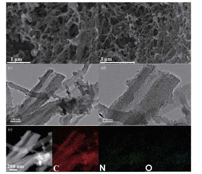
It can be verified that there were many micropore structures on the surface of NPCF material through TEM images in Fig. 1c and 1d. The high-resolution TEM (HRTEM) images in Fig.S1 (Supporting information) can clearly show that there was no obvious ordered structure, which means that the material was amorphous. Fig. 1e showed the elemental distribution of the carbon material analyzed by TEM-EDS, which confirms that C, N, and O elements were uniformly distributed on the surface of the carbon material.
XRD pattern of NPCF is shown in Fig. 2a, an obvious carbon broad peak appeared at 25.7°, corresponding to the (002) plane, and a small peak appeared at 43°, corresponding to the (100) plane, indicating the disordered structure of NPCF, which suggested that the carbon interlayer spacing of NPCF was larger than that of graphite, facilitating the intercalation of Na ions[18-19]. Fig. 2b shows the Raman spectrum of NPCF. The intensity ratio of the D peak and the G peak (ID/IG) can indicate the degree of defects and disorder of the hard carbon material[20]. The ID/IG value of NPCF was 3.18, showing extremely high defects. This phenomenon has been reported mostly in heteroatom-doped carbon materials[21]. More defects are beneficial to promote the adsorption of Na ions to further enhance the active center and promote fast charge transfer during (de)sodiumization[22]. As shown in Fig. 2c, it can be drawn from the nitrogen adsorption-desorption isotherm that the type Ⅰ isotherm has a specific surface area of 897 m2·g-1, which indicated the existence of micropores[23]. The micropores were mainly distributed between 0.4-0.6 nm from the pore size distribution curve in Fig. 2d[24].
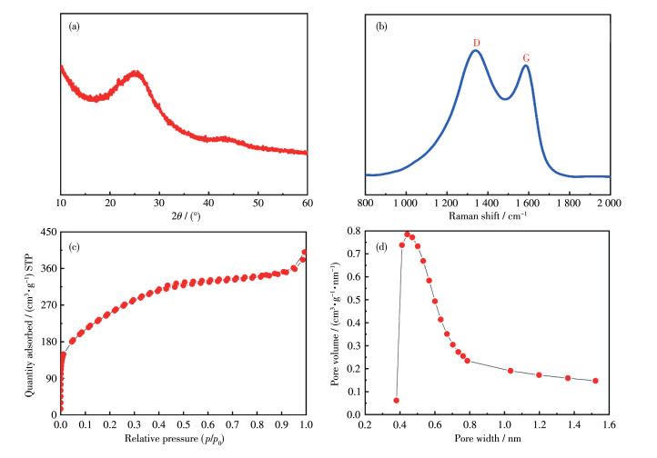
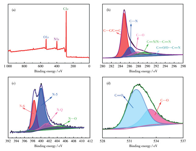
Fig. 3 shows the measured XPS spectra of NPCF, analyzing the surface composition and valence states of the elements in NPCF. There was a prominent C1s peak at 285 eV, a N1s peak at 400 eV, and an O1s peak at 530 eV. NPCF consisted of 80.5% C, 13.3% N, and 6.2% O (atomic fraction). To further illustrate the valence state distribution of each element, the high- resolution XPS spectra of C1s, N1s, and O1s were analyzed. In the C1s high-resolution XPS spectrum, the peaks of C—C/C=C, C—N, C—O, C=N/N—C=N, C=O/O—C=O are located at 284.8, 286.4, 287.6, 289.1, and 290.9 eV, respectively[25-26]. The detailed state of N is shown in Fig. 3c, the peak at 398.3 eV belongs to pyridine nitrogen (N-6), the peak at 400.0 eV belongs to pyrrolic nitrogen (N-5), the peak at 401.2 eV belongs to graphite nitrogen (N-Q), and the peak at 404.6 eV belonged to nitrogen oxide (N—O)[27-29]. The N-5 and N-6 in NPCF can act as active centers to enhance the storage capacity of sodium ions[25]. The two peaks of the O1s high-resolution XPS spectrum are assigned to C=O (531.7 eV) and C—O—C (533.2 eV). The high percentage of C=O was conducive to the adsorption of sodium ions.
To further study the anode of NPCF materials, NPCF and metal sodium were assembled into a half-cell, and 1 mol·L-1 NaClO4 was used as the electrolyte in EC/DEC and 5% FEC for analysis, and the cycle of sweep rate of 0.1 mV·s-1 as shown in the voltammetric curve, there were obvious cathode peaks at 1.1 and 2.1 V, which were the decomposition of the electrolyte and the formation of the solid electrolyte interfacial (SEI) film[30-31]. As the SEI film formed in the process of sodium conversion of electrode materials, NPCF was composed of inorganic and organic parts. The organic components were composed of electrolytes (EC/DEC) decomposition, such as alkyl sodium carbonate (ROCO3Na), sodium carbonate (Na2CO3), etc. The inorganic components were decomposed or captured by the electrochemical decomposition of electrolyte salts, and the products were mainly composed of NaCl and NaF. In addition, the inorganic component of SEI is closer to the electrode side, while the organic component is closer to the outermost layer of the electrolyte[32]. After the first cycle, the CV curves in Fig. 4a were almost completely overlapped, demonstrating the excellent reversible properties of NPCF[33]. Fig. 4b is the CV test result of NPCF in the range of 0.1-0.5 mV·s-1 scan rate. The scan results can further analyze the contribution of capacitance to the electrochemical performance of NPCF. The relationship between the measured current (i) and the scan rate (v) can be expressed by the following formula:
|
|
(1) |
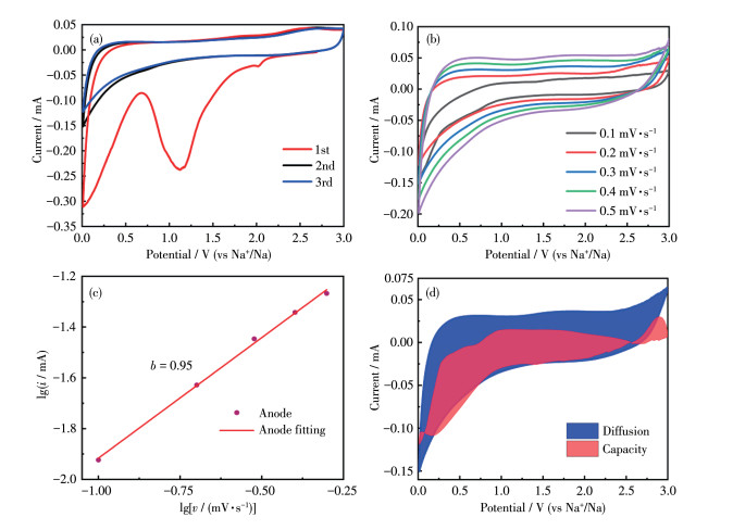
The values of a and b can be obtained by fitting the functions of lg i and lg v as shown in Fig. 4c[34-35]. When the value of b is close to 1, it indicates capacitive behavior. When the value of b is close to 0.5, it indicates the behavior of diffusion control[36]. The b value of NPCF was 0.95, indicating that its sodium storage mechanism was dominated by capacitive behavior, and the capacitive behavior was mainly caused by the surface of NPCF. The high nitrogen doping promotes the pseudocapacitive behavior, and the large specific surface area enhances the double-layer capacitance. The contribution rate of sodium ion storage to total capacitance can be obtained by the following equation:
|
|
(2) |
k1v represents the contribution of capacitive behavior to the total capacitance, and k2v1/2 represents the contribution of the diffusion process to the total capacitance[34]. It can be seen from Fig. 4d that the capacitance behavior of NPCF at 0.3 mV·s-1 was 48.28% of the total capacity, and Fig.S2 shows that the contribution to the total capacitance at 0.5 mV·s-1 was 56.6%. As the scan rate increased, the capacitive behavior gradually became the main contribution[37]. In addition, the fitting value of the redox peak potential in Fig. 4d exceeded the experimental value, mainly because the ohmic resistance is ignored, which leads to a deviation in its value[38-40].
In Fig. 5a, the analysis time-voltage curve showed a linear relationship, the iR (voltage) drop at low current density was negligible, and the charge-discharge curve was triangular, indicating the formation of an electrochemical double layer on the electrode surface[14, 19]. The performance of the NPCF battery was studied by EIS (Fig. 5b). EIS curve was composed of a semicircle in the high-frequency region and a slope line in the low-frequency region[41]. At the early stage of the battery cycle, due to insufficient penetration of the electrolyte, the electrode stability was poor, resulting in a very large ohm resistance of the battery, which gradually decreased after the cycle was stabilized. After the cycle stability, the electrolyte and the electrode material were fully infiltrated, and the ohm resistance showed finally stable. The resistance of the battery remained in a low range after 2 500 cycles, indicating that the battery had good cycle performance.
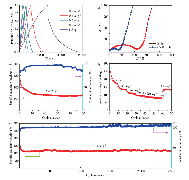
As shown in the analysis of Fig. 5, NPCF was analyzed in the half-cell. A metallic sodium sheet was used as the counter electrode, and the electrolyte was EC/DEC and 5% FEC in 1 mol·L-1 NaClO4 solution. The storage capacity of NPCF was tested by galvanostatic charge-discharge experiments. The area mass load of each electrode active material was ca. 1.0 mg·cm-2. The potential range was measured from 0.01 to 3 V, and the current density increased from 0.1 to 1 A·g-1. Fig. 5c shows that the capacity remained stable at 218 mAh·g-1 after 100 cycles at a current of 0.1 A·g-1. The surface morphology of the electrode before and after cycling was observed by SEM and the results are illustrated in Fig.S3. Fig.S3a and S3c show that the structure of the active material was still maintained, the cross-sectional SEM images (Fig.S3b and S3d) further confirm that the electrode thickness has not been changed even after deep cycling for 100 times. Thus, the superior stability of the electrode has been well verified. In addition, at current densities of 0.1, 0.2, 0.4, 0.8, 1, and 0.1 A·g-1, the specific capacity of NPCF was 169, 133, 106, 93, 86, 80, and 133 mAh·g-1, respectively, the current continued to increase and finally returned to 0.1 A·g-1, the specific capacity of the battery could return to 133 mAh·g-1. The battery has excellent magnification performance, which is related to a large number of microporous structures on the surface of NPCF in addition to the high nitrogen doping. Due to the large radius of Na ions, the intercalation and deintercalation process of Na+ is slow, and it is very challenging to obtain high-rate anodes with long-term cycling stability. High capacity of 114 mAh·g-1. At the same time, the cycle data of NPCF at different preparation temperatures (700 and 900 ℃) were compared (Fig.S4-S6). Under the current density of 0.1 A·g-1, the specific capacities after 100 cycles were 214 and 164 mAh·g-1, respectively, and the specific capacity was maintained at 140 mAh·g-1 (700 ℃) and 123 mAh·g-1 (900 ℃) after 1 000 cycles. Comparing the rate performance at 700 and 900 ℃, when the current density increased and finally returned to 0.1 A·g-1, the specific capacity of the material remained at 201 and 99 mAh·g-1. When the temperature is too high, the nitrogen content will decrease during calcination, and the decrease in temperature will lead to the instability of the material structure, and the expansion will occur in the process of sodium ion embedding and removal[37]. Compared to other reported properties of carbon materials, such as NPCNs-600-N[14], CPCF-700[15], N-HCNWs[42], HC[43], and APSRC[44], etc. (Fig.S7), NPCF in this work has better magnification performance and specific capacity. These results show that the carbon nanowires synthesized by this convenient method have good rate capability and excellent long-cycle performance, and the micropores provided by high nitrogen doping and large specific surface enhance the ion diffusion rate.
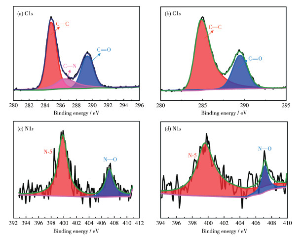
To explain the mechanism of adsorption and desorption of sodium ions, and to clarify the adsorption sites and active centers of sodium ions, the XPS analysis of electrode material with different charges was carried out. The change in the valence state of C ia shown in Fig. 6a and 6b. When charging to 3 V, the original characteristic peaks became C—C (284.7 eV), C—N (286.4 eV), and C=O (289.3 eV). After discharge to 0.01 V, the characteristic peaks change to C—C and C=O. The disappearance of C—N characteristic peaks indicated that nitrogen doping effectively assisted the embedding and removal of sodium ions. Fig. 6c and 6d show the change in N valence states. When charged to 3 V, the characteristic peaks of N1s are N-5 (399.8 eV) and N—O (407.2 eV). At this time, the area ratio of N-5 and N—O was 3∶1. When discharged to 0.01 V, the area ratio of peaks increased to 7∶1. The content of N-5 was increased. It has been proved that high nitrogen doping can improve the active site for Na storage, which is conducive to the adsorption and diffusion of Na+ and enhance the storage of sodium[45-46].
The carbon nanowire material NPCF was obtained by pyrolysis of melamine and potassium citrate, and different graphitized materials were obtained by adjusting the temperature of pyrolysis. Abundant heteroatom doping and abundant microporous structure provide excellent electrochemical performance for Na‑ion capacitors. It can maintain 218 mAh·g-1 after 100 cycles at a current density of 0.1 A·g-1 and 140 mAh·g-1 at a current density of 1 A·g-1. However, the formation mechanism of NPCF still needs further research to pave the way for the commercialization of sodium ion capacitors, and it can also lead to other energy fields.
Supporting information is available at
Zhu J, Roscow J, Chandrasekaran S, Deng L, Zhang P, He T, Wang K, Huang L. Biomass‑derived carbons for sodium-ion batteries and sodium-ion capacitors[J]. ChemSusChem, 2020, 13(6): 1275-1295. doi: 10.1002/cssc.201902685
Poullikkas A. A comparative overview of large-scale battery systems for electricity storage[J]. Renew. Sust. Energ. Rev., 2013, 27: 778-788. doi: 10.1016/j.rser.2013.07.017
Meng Y F, Liang H J, Zhao C D, Li W H, Gu Z Y, Yu M X, Zhao B, Hou X K, Wu X L. Concurrent recycling chemistry for cathode/anode in spent graphite/LiFePO4 batteries: Designing a unique cation/anion-Co-workable dual-ion battery[J]. J. Energy Chem., 2022, 64: 166-171. doi: 10.1016/j.jechem.2021.04.047
Liu T H, Liu F, Qu Z H, Chen J L, Liu H, Tan Y Q, Guo J B, Yan Y, Zhao S, Zhao X S, Nie X M, Ma X M, Pei Z X, Liu M K. High sulfur loading and shuttle inhibition of advanced sulfur cathode enabled by graphene network skin and N, P, F-doped mesoporous carbon interfaces for ultra-stable lithium sulfur battery[J]. Nano Res. Energy, 2023, 2: e9120049. doi: 10.26599/NRE.2023.9120049
Liu T F, Zhang Y P, Jiang Z G, Zeng X Q, Ji J P, Li Z H, Gao X H, Sun M H, Lin Z, Ling M, Zheng J C, Liang C D. Exploring competitive features of stationary sodium ion batteries for electrochemical energy storage[J]. Energy Environ. Sci., 2019, 12(5): 1512-1533. doi: 10.1039/C8EE03727B
Hwang J Y, Myung S T, Sun Y K. Sodium-ion batteries: Present and future[J]. Chem. Soc. Rev., 2017, 46(12): 3529-3614. doi: 10.1039/C6CS00776G
Pan H, Hu Y S, Chen L. Room-temperature stationary sodium-ion batteries for large-scale electric energy storage[J]. Energy Environ. Sci., 2013, 6(8): 2338-2360. doi: 10.1039/c3ee40847g
Liang H J, Gu Z Y, Zheng X Y, Li W H, Zhu L Y, Sun Z H, Meng Y F, Yu H Y, Hou X K, Wu X L. Tempura-like carbon/carbon composite as advanced anode materials for K-ion batteries[J]. J. Energy Chem., 2021, 59: 589-598. doi: 10.1016/j.jechem.2020.11.039
Shen F, Zhu H L, Luo W, Wan J Y, Zhou L H, Dai J Q, Zhao B, Han X G, Fu K, Hu L B. Chemically crushed wood cellulose fiber towards high-performance sodium-ion batteries[J]. ACS Appl. Mater. Interfaces, 2015, 7(41): 23291-23296. doi: 10.1021/acsami.5b07583
Hong K L, Qie L, Zeng R, Yi Z Q, Zhang W, Wang D, Yin W, Wu C, Fan Q J, Zhang W X, Huang Y H. Biomass derived hard carbon used as a high performance anode material for sodium ion batteries[J]. J. Mater. Chem. A, 2014, 2(32): 12733-12738. doi: 10.1039/C4TA02068E
Lv W M, Wen F S, Xiang J Y, Zhao J, Li L, Wang L M, Liu Z Y, Tian Y J. Peanut shell derived hard carbon as ultralong cycling anodes for lithium and sodium batteries[J]. Electrochim. Acta, 2015, 176: 533-541. doi: 10.1016/j.electacta.2015.07.059
Zhu X M, Jiang X Y, Liu X L, Xiao L F, Cao Y L. A green route to synthesize low-cost and high-performance hard carbon as promising sodium-ion battery anodes from sorghum stalk waste[J]. Green Energy Environ., 2017, 2(3): 310-315. doi: 10.1016/j.gee.2017.05.004
Lu P R, Xia J L, Dong X L. Rapid sodium-ion storage in hard carbon anode material derived from Ganoderma lucidum residue with inherent open channels[J]. ACS Sustain. Chem. Eng., 2019, 7(17): 14841-14847. doi: 10.1021/acssuschemeng.9b02906
Wang C, Yu Q T, Zhao N, Li B H, Shen W C, Kang F Y, Huang Z H, Lv R T. g-C3N4 templated mesoporous carbon with abundant heteroatoms as high-rate anode material for dual-carbon sodium ion hybrid capacitors[J]. J. Materiomics, 2022, 8(6): 1149-1157. doi: 10.1016/j.jmat.2022.06.004
Ramachandran K, Subburam G, Liu X H, Huang M G, Xu C, Ng D H L, Cui Y X, Li G C, Qiu J X, Wang C, Lian J B. Nitrogen-doped porous carbon nanofoams with enhanced electrochemical kinetics for superior sodium-ion capacitor[J]. Rare Met., 2022, 41(7): 2481-2490. doi: 10.1007/s12598-022-01992-5
Wang L X, Shen J, Li L, Liu P D, Fang H, Li X F, Song Y H, Zhang L S. Heteroatom-doped hollow carbon micro-tube derived from platanus catkins fiber for sodium ion supercapacitor[J]. Inorg. Chem. Commun., 2020, 114: 107817. doi: 10.1016/j.inoche.2020.107817
Fombona-Pascual A, Díez N, Fuertes A B, Sevilla M. Eco-friendly synthesis of 3D disordered carbon materials for high-performance dual carbon Na-ion capacitors[J]. ChemSusChem, 2022, 15(19): e202201046.
Yan Y, Xu M J, Luo Y Q, Ma J Y, Pang H, Xue H G. Preparation of N, P Co-doped activated carbons derived from honeycomb as an electrode material for supercapacitors[J]. RSC Adv., 2017, 7(75): 47448-47455. doi: 10.1039/C7RA08759D
Diez N, Sevilla M, Fuertes A B. A dual carbon Na-ion capacitor based on polypyrrole-derived carbon nanoparticles[J]. Carbon, 2023, 201: 1126-1136. doi: 10.1016/j.carbon.2022.10.036
Shaji N, Ho C W, Nanthagopal M, Santhoshkumar P, Sim G S, Lee C W. Biowaste‑derived heteroatoms-doped carbon for sustainable sodium-ion storage[J]. J. Alloy. Compd., 2021, 872: 159670. doi: 10.1016/j.jallcom.2021.159670
Guo D, Ding B, Hu X, Wang Y H, Han F Q, Wu X L. Synthesis of boron and nitrogen codoped porous carbon foam for high performance supercapacitors[J]. ACS Sustain. Chem. Eng., 2018, 6(9): 11441-11449. doi: 10.1021/acssuschemeng.8b01435
Long B, Ma J F, Song T, Wang X Y, Tong Y X. Tailoring superficial morphology, defect and functional group of commercial carbon cloth for a flexible, stable and high-capacity anode in sodium ion battery[J]. Electrochim. Acta, 2021, 374: 137934. doi: 10.1016/j.electacta.2021.137934
Zhou M, Pu F, Wang Z, Guan S Y. Nitrogen-doped porous carbons through KOH activation with superior performance in supercapacitors[J]. Carbon, 2014, 68: 185-194. doi: 10.1016/j.carbon.2013.10.079
Deng X, Zhao B T, Zhu L, Shao Z P. Molten salt synthesis of nitrogen-doped carbon with hierarchical pore structures for use as high-performance electrodes in supercapacitors[J]. Carbon, 2015, 93: 48-58. doi: 10.1016/j.carbon.2015.05.031
Chen C, Huang Y, Zhu Y D, Zhang Z, Guang Z X, Meng Z Y, Liu P B. Nonignorable influence of oxygen in hard carbon for sodium ion storage[J]. ACS Sustain. Chem. Eng., 2020, 8(3): 1497-1506. doi: 10.1021/acssuschemeng.9b05948
Matsoso B J, Ranganathan K, Mutuma B K, Lerotholi T, Jones G. Time-dependent evolution of the nitrogen configurations in N-doped graphene films[J]. RSC Adv., 2016, 6(108): 106914-106920. doi: 10.1039/C6RA24094A
Chen C, Yu D F, Zhao G Y, Du B S, Tang W, Sun L, Sun Y, Besenbacher F, Yu M. Three-dimensional scaffolding framework of porous carbon nanosheets derived from plant wastes for high-performance supercapacitors[J]. Nano Energy, 2016, 27: 377-389. doi: 10.1016/j.nanoen.2016.07.020
Zhou Q X, Su Z B, Tang Y D, Ai L, Fu G T, Wu Z X, Sun D M, Tang Y W. Pt-like oxygen reduction activity induced by cost-effective MnFeO2/N-carbon[J]. Chem.-Eur. J., 2019, 25(24): 6226-6232. doi: 10.1002/chem.201900638
郑淑娟, 李嘉欣, 钟雯诗, 姜伟, 胡庚申. 壳聚糖基多孔碳材料的制备及其超级电容性能[J]. 无机化学学报, 2023,39,(3): 492-500. ZHENG S J, LI J X, ZHONG W S, JIANG W, HU G S. Preparation and electrochemical performance for supercapacitors of chitosan-based porous carbon materials[J]. Chinese J. Inorg. Chem., 2023, 39(3): 492-500.
Chen C, Huang Y, Meng Z Y, Zhang J X, Lu M W, Liu P B, Li T H. Insight into the rapid sodium storage mechanism of the fiber-like oxygen-doped hierarchical porous biomass derived hard carbon[J]. J. Colloid Interface Sci., 2021, 588: 657-669. doi: 10.1016/j.jcis.2020.11.058
Wang Z H, Yang H Y, Liu Y R, Bai Y, Chen G H, Li Y, Wang X R, Xu H J, Wu C, Lu J. Analysis of the stable interphase responsible for the excellent electrochemical performance of graphite electrodes in sodium-ion batteries[J]. Small, 2020, 16(51): 2003268. doi: 10.1002/smll.202003268
Eshetu G G, Diemant T, Hekmatfar M, Grugeon S, Behm R J, Laruelle S, Armand M, Passerini S. Impact of the electrolyte salt anion on the solid electrolyte interphase formation in sodium ion batteries[J]. Nano Energy, 2019, 55: 327-340. doi: 10.1016/j.nanoen.2018.10.040
Yang C H, Xiong J W, Ou X, Wu C F, Xiong X H, Wang J H, Huang K, Liu M L. A renewable natural cotton derived and nitrogen/sulfur Co-doped carbon as a high-performance sodium ion battery anode[J]. Mater. Today Energy, 2018, 8: 37-44. doi: 10.1016/j.mtener.2018.02.001
Sathiya M, Prakash A S, Ramesha K, Tarascon J M, Shukla A K. V2O5-anchored carbon nanotubes for enhanced electrochemical energy storage[J]. J. Am. Chem. Soc., 2011, 133(40): 16291-16299. doi: 10.1021/ja207285b
Augustyn V, Come J, Lowe M A, Kim J W, Taberna P L, Tolbert S H, Abruña H D, Simon P, Dunn B. High-rate electrochemical energy storage through Li+ intercalation pseudocapacitance[J]. Nat. Mater., 2013, 12(6): 518-522. doi: 10.1038/nmat3601
Li S, Qiu J X, Lai C, Ling M, Zhao H J, Zhang S Q. Surface capacitive contributions: Towards high rate anode materials for sodium ion batteries[J]. Nano Energy, 2015, 12: 224-230. doi: 10.1016/j.nanoen.2014.12.032
Chen C, Huang Y, Meng Z Y, Lu M W, Xu Z P, Liu P B, Li T H. Experimental design and theoretical evaluation of nitrogen and phosphorus dual-doped hierarchical porous carbon for high-performance sodium-ion storage[J]. J. Mater. Sci. Technol., 2021, 76: 11-19. doi: 10.1016/j.jmst.2020.11.014
Pu X J, Zhao D, Fu C L, Chen Z X, Cao S N, Wang C S, Cao Y L. Understanding and calibration of charge storage mechanism in cyclic voltammetry curves[J]. Angew. Chem. Int. Ed., 2021, 6(39): 21310-21318.
Chen M Z, Chen L N, Hu Z, Liu Q N, Zhang B W, Hu Y X, Gu Q F, Wang J L, Wang L Z, Guo X D, Chou S L, Dou S X. Carbon-coated Na3.32Fe2.34(P2O7)2 cathode material for high-rate and long-life sodium-ion batteries[J]. Adv. Mater., 2017, 29(21): 1605535. doi: 10.1002/adma.201605535
Ma X D, Wu X H, Shen P K. Rational design of Na4Fe3(PO4)2(P2O7) nanoparticles embedded in graphene: Toward fast sodium storage through the pseudocapacitive effect[J]. ACS Appl. Energy Mater., 2018, 1(11): 6268-6278. doi: 10.1021/acsaem.8b01275
Li C, Fu Q, Zhao K J, Wang Y P, Tang H, Li H H, Jiang H B, Chen L. Nitrogen and phosphorous dual-doped graphene aerogel with rapid capacitive response for sodium-ion batteries[J]. Carbon, 2018, 139: 1117-1125. doi: 10.1016/j.carbon.2018.06.035
Li D D, Ye C, Chen X Z, Wang S Q, Wang H H. A high energy and power sodium-ion hybrid capacitor based on nitrogen-doped hollow carbon nanowires anode[J]. J. Power Sources, 2018, 382: 116-121. doi: 10.1016/j.jpowsour.2018.02.036
Yu K H, Wang X R, Yang H Y, Bai Y, Wu C. Insight to defects regulation on sugarcane waste-derived hard carbon anode for sodium-ion batteries[J]. J. Energy Chem., 2021, 55: 499-508. doi: 10.1016/j.jechem.2020.07.025
Gao L, Wang Z J, Zhang L L, Yang X L. Potassium ion anode versus sodium ion anode: Potato starch residue derived carbon material as a case study[J]. J. Solid State Electrochem., 2022, 26(2): 343-352. doi: 10.1007/s10008-021-05052-3
Wang X T, Yang Y, Guo J Z, Gu Z Y, Ang E H, Sun Z H, Li W H, Liang H J, Wu X L. An advanced cathode composite for co-utilization of cations and anions in lithium batteries[J]. J. Mater. Sci. Technol., 2022, 102: 72-79. doi: 10.1016/j.jmst.2021.05.074
Guo J Z, Zhang H X, Gu Z Y, Du M, Lü H Y, Zhao X X, Yang J L, Li W H, Kang S, Zou W, Wu X L. Heterogeneous NASICON-type composite as low-cost, high-performance cathode for sodium-ion batteries[J]. Adv. Funct. Mater., 2022, 32(52): 2209482. doi: 10.1002/adfm.202209482

Figure 1 (a, b) SEM images, (c, d) TEM image, (e) HRTEM images and the corresponding elemental mappings of NPCF

Figure 2 (a) XRD pattern, (b) Raman spectrum, (c) nitrogen adsorption‐desorption isotherm, and (d) pore size distribution of NPCF

Figure 4 (a) CV curves at 0.1 mV·s-1, (b) CV curves at various scan rates, (c) b values of redox peaks, (d) capacitive contribution at 0.3 mV·s-1 of NPCF

Figure 5 (a) Galvanostatic charge‐discharge curves at various current densities, (b) Nyquist plots from 0.01 Hz to 100 kHz, (c) discharge cycle profiles at 0.1 A·g-1, (d) rate performance from 0.1 to 1 A·g-1, and (e) discharge cycle profiles at 1 A·g-1 of NPCF

 扫一扫看文章

扫一扫关注我们
 下载:
下载:

 下载:
下载:

