Table 1.
Summary of the Applications of In Situ TEM for Catalysts
Citation:
Chen Sun, Kuo Liu, Jian Zhang, Qian Liu, Xijun Liu, Lili Han. In Situ Transmission Electron Microscopy and Three-Dimensional Electron Tomography for Catalyst Studies[J]. Chinese Journal of Structural Chemistry,
2022, 41(10): 221005.
doi:
10.14102/j.cnki.0254-5861.2022-0187

In Situ Transmission Electron Microscopy and Three-Dimensional Electron Tomography for Catalyst Studies
English
In Situ Transmission Electron Microscopy and Three-Dimensional Electron Tomography for Catalyst Studies
Abstract:
An in-depth understanding of the catalytic reaction mechanism is the key to designing efficient and stable catalysts. In situ transmission electron microscope (TEM) is the most powerful tool to visualize and analyze the microstructures of catalysts during catalysis. In situ TEM combined with three-dimensional (3D) electron tomography (ET) reconstruction technique enables interrogations of catalysts' structural dynamics and chemical changes in high temporal and spatial dimensions. In this review, we discuss and summarize the recent advances in in situ TEM together with 3D ET for catalyst studies. Topics include the latest research progress of in situ TEM imaging as well as 3D visualization and quantitative analysis of catalysts. We also pay particular attention to artificial intelligence (AI)-enhanced smart 3D ET. These include deep learning (DL)-based data compression and storage for the analysis of large TEM data, recovery of wedge-shaped information lost in 3D ET reconstructions, and DL models for reducing residual artifacts in 3D reconstructed images. Finally, the challenges and development prospects of current in situ TEM and 3D ET research are discussed.
-
Key words:
- in situ TEM
- / catalyst
- / electron tomography
- / 3D reconstruction
- / artificial intelligence
- / machine learning
-
INTRODUNTION
Energy crisis and environmental pollution are urgent problems in modern society.[1-3] More efficient and environmentally friendly catalysts are needed to address the issues.[4-7] In situ monitoring of the structural evolution of catalysts is essential to gain insight into the relationship between the structures and properties of catalysts. Transmission electron microscope (TEM) is a powerful tool for observing and testing the microstructures of materials, chemistry, physics, biology, and other fields of scientific research.[8-11] Especially in the past 20 years, with the rapid development of electron emission sources, aberration correctors, diffraction and spectroscopy techniques, TEM has achieved subangstrom spatial resolution, [12, 13] mili-electron volt energy resolution, [14] and sensitivity to individual atoms.[15-19] Technological advances in TEM have laid a foundation for the high-resolution in situ study of catalysts.
In situ TEM can characterize the dynamic behavior of catalysts under various external stimuli such as gas, liquid, heating, cooling, electron beam, light, force, and electrical bias.[17, 20-24] A variety of in situ TEM holders have been developed to apply these external stimuli. The advent of micro-electro-mechanical systems (MEMS) and in situ liquid/gas cell TEM (LC/GC-TEM) has promoted the miniaturization and diversification of in situ experimental equipment.[25, 26] Furthermore, in situ TEM introduces many accessories, such as energy dispersive X-ray spectroscopy (EDX) and electron energy loss spectroscopy (EELS), which can obtain information on the elemental composition, chemical bonds, element valence states and spatial distribution structure of electrons of the specimen.[15, 19] The in situ TEM characterization technique has been applied to catalytic fields such as thermal catalysis, electrochemical catalysis and photocatalysis. However, most studies are based only on two-dimensional (2D) TEM characterization, which is insufficient to relate the complete three-dimensional (3D) structure of catalysts to their properties, especially for catalysts with complex nanostructures. Therefore, a characterization method that can obtain the 3D structure and chemical spatial distribution information of catalysts in real time is required to explore various catalytic reaction mechanisms deeply. Electron tomography (ET) is one of the methods for 3D imaging by reconstructing a series of 2D projected images tilted with a fixed axis as the input of the 3D reconstruction model.[27-32] High-resolution imaging of in situ and quasi-in situ ET reconstructions in liquid/gas phase environments has been achieved by in situ TEM-based ET.[33-38]
Ideally, 3D ET must acquire a full oblique projection image from -90° to +90° as input data for a perfect 3D reconstruction. However, in practical applications, obtaining a complete diagonal projection image (usually between -70° and +70°) is difficult due to the limitations of the experimental equipment, experimental environment, sample state, and other factors, which is called the "missing wedge" question.[39, 40] This problem can lead to stretching, artifacts and reduced quality and resolution of the reconstructed model. However, when the issue of "missing wedge" is processed and analyzed by traditional mathematical methods, the reconstruction cannot achieve the desired result because the actual acquired projection images are missing or the parameters to be adjusted are different.[41-46] Artificial intelligence (AI) is an emerging technological science for simulating, extending, and expanding human intelligence. Deep learning (DL) is a branch that has made outstanding contributions to image processing and intelligent microscopy.[47-49] 3D ET assisted by generative adversarial networks (GAN) can recover missing information without supervision, and this method can obtain high-quality reconstructed models. The current highest resolution of 3D imaging enhanced by the DL-GAN method has reached 0.71 Å.[50-53] AI-assisted in situ 3D ET provides a new method to obtain 3D structural and chemical information on catalysts.
In this review, we provide an overview of recent advances in in situ TEM and 3D ET techniques relevant to the catalysis discipline, with topics including chemical or physical dynamic processes of catalysts in vacuum, gas-phase, and liquid-phase environments, with different in situ settings. In addition, we also pay special attention to the application of 3D ET technique with AI to highlight the advantages of AI in the field of materials imaging. Finally, we discuss the challenges faced by in situ TEM and 3D ET techniques, as well as possible solutions to these challenges. The content of this review is organized as follows: Section 2 presents recent advances in the application of in situ TEM in the field of catalysis. Section 3 discusses the application of in situ 3D tomography in the field of catalysis and recent advances in 3D tomography imaging combined with AI. Section 4 makes concluding remarks and presents pressing challenges and prospects for in situ TEM characterization.
IN SITU TEM STUDY OF CATALYSTS
Correlating the physicochemical properties of catalysts with corresponding activity, selectivity, and stability is crucial to gaining insight into their catalytic mechanisms. Generally speaking, the performance of catalysts depends on structure, morphology, and chemical composition.[6] Compared with traditional TEM characterization, in situ TEM can monitor the dynamic structural changes of catalysts in the in situ environment and study catalysts under different catalytic conditions, such as heating, cooling, electron beams, reaction environments (liquid or gas reaction cells) and photons.[15, 54-58] In this section, we summarize the recent developments of in situ TEM technique according to the different in situ setups, reaction environments, and types of materials. Some representative reports are presented in Table 1.
Table 1

 DownLoad:
CSV
DownLoad:
CSV
In situ TEM setup Materials Reaction environment Reaction/process Ref. heating Pt/C, Pt-Pd/Al2O3 vacuum environment; 500 to 975 ℃ structure evolution [54] Au nanoparticles (NPs) vacuum environment; 300 to 700 ℃ structure evolution [59] Ag, Pt nanocrystals vacuum environment; 25 to 500 ℃ structure evolution [60] Ni-Fe layered double
hydroxide nanocrystalsvacuum environment; 25 to 850 ℃ structure evolution [61] Pt3Co nanocrystals vacuum environment; at 750 ℃ structure evolution [62] LaNiO3 vacuum environment; 23 to 800 ℃ structure evolution [63] heating, gas-phase Co NPs O2 gas; 150 to 250 ℃ and 250 to 350 ℃ oxidation reaction [64] Pt-Co NPs O2 gas, H2 gas; 250 to 400 ℃ oxidation and reduction reactions [65] Ag/SiO2 O2 gas; at 330 ℃ oxidation reaction [66] Pd nanocrystals O2 gas, H2 gas; 200 to 300 ℃ oxidation and reduction reactions [67] PdZn/ZnO nanocrystals H2/He (10 vol%) gas and pure He gas; at 100 ℃ reduction reactions [68] TiO2 nanocrystals water vapor gas, CO gas; 500 to 700 ℃ oxidation reaction [22] Ni-Co alloy NPs C2H4 gas, H2 gas, He gas; 300 to 700 ℃ structure evolution carbon nanofiber growth [69] Ni catalyst, carbon H2 gas, CH4 gas; at 450 ℃ structure evolution; carbon nanofiber growth [23] gas-phase single-atom Co applied potential bias electrochemical reaction [70] nanoporous gold (NPG) CO/air-gas mixture, N2 gas, O2 gas, pure CO gas oxidation reaction [71] liquid-phase Au NPs irradiation of high-energy electron beam crystal growth [72] Pt NPs irradiation of high-energy electron beam crystal growth [73] Pt NPs irradiation of high-energy electron beam crystal growth [74] Pb3O4 nanocrystals irradiation of high-energy electron beam crystal growth [75] Pt-Fe NPs applied potential bias electrochemical reaction [76] Pt-Ni alloy NPs applied potential bias electrochemical reaction [77] Cu NPs applied potential bias electrochemical reaction [78] TiO2 light exposure photocatalytic reaction [79] Cu2O NPs light exposure photocatalytic reaction [24] In Situ Heating-Induced Evolution of Nanostructures
The studies on nanoparticles (NPs) have illustrated that many critical industrial catalytic processes are carried out at high reaction temperatures.[80-82] In addition, catalyst particles usually need to be treated at high temperatures to change their surface structures and composition, so there are essential requirements for the thermal stability of the catalyst at high temperatures. The in situ observation of the structure and morphology of catalysts with temperature plays a crucial role in understanding the catalytic reaction mechanism and designing high-performance catalysts. In this section, we summarize the application of in situ heating function in the structural evolution of solid catalysts. The in situ heating sample holder introduces the in situ heating function into TEM, allowing researchers to monitor the dynamic behavior of catalysts during heating in real time.[56, 83, 84] The in situ heating sample holder based on the MEMS technique is shown in Figure 1.
Figure 1
 Figure 1. (a) Schematic diagram of the structure of the in situ heating seat and the MEMS device. (b) Scanning electron microscope images of heating spirals and through-hole windows of MEMS devices.[84]
In heterogeneous catalysts, metal NPs constitute the active sites of heterogeneous catalysts and sintering refers to the growth of supported metal NPs. It should be noted that sintering and thermal deactivation can cause changes in catalyst activity.[85] Gontard et al.[54] studied the active phase of Pt NPs on carbon black and the dynamic process of sintering Pt-Pd NPs on (γ and α)-Al2O3 with temperature by in situ heating. Their results showed that the sintering of Pt NPs closely combined with carbon black carriers was accelerated. On the contrary, the sintering phenomenon of isolated small particles proceeded slowly, which was possibly caused by Ostwald ripening. The decrease in catalyst activity can be inferred by quantifying the active surface area of the Pt particles. Similarly, Yoshida et al. also observed the Ostwald ripening of Pt NPs on amorphous carbon carriers under high-energy radiation.[86, 87] With the help of in situ characterization, the understanding of the Ostwald ripening mechanism of metal NPs on mesoporous materials can be deepened.
Santa Barbara amorphous-15 (SBA-15) is a highly stable mesoporous silica sieve with a unique porous structure, which provides an excellent model particle for studying the agglomeration behavior of catalysts. Liu et al.[59] reported in situ observations of the sintering process of SBA-15 supported AuNPs. TEM images of Au NPs in SBA-15 at 550 and 700 ℃ during the sintering process are shown in Figure 2a. They found that the internal morphology of the mesoporous channel of the SBA-15 carrier had a crucial effect on the sintering behavior of Au NPs, and there was no linear relationship with the pore size. The micropores on the mesoporous wall of the carrier provided stable positions for Au NPs and restricted their migration and aggregation, thus hindering the sintering of Au NPs. Furthermore, it was found that when the two NPs are close enough, the high temperature induced the expansion of the conducting electron cloud outside the Au NPs, causing the agglomeration of particles. In situ TEM has also been applied to observe dynamic structural changes during in situ heating of 2D nanometer Ni-Fe layered double hydroxides (LDH). It can be observed that the crystal structure of Ni-Fe LDH was destroyed during heating, and spherical oxidized Ni NPs formed on the surface.[61, 88] The oxidation of Ni atoms also existed in the heating process of the perovskite materials (LaNiO3). Cao et al. observed that Ni atoms in LaNiO3 dissolved and formed Ni nanoparticles at 640 to 660 ℃.[63] Since Ni atoms were more likely to migrate and aggregate in the grain boundary region, the grain volume of the parent LaNiO3 shrinked sharply, as shown in Figure 2b. In addition, during the dissolution of Ni atoms, the lattice oxygen in the perovskite was released and the surface of Ni NPs was oxidized. This work provided direct evidence that active lattice oxygen overflowed from the decomposed LaNiO3 structure to the dissolved Ni particles to form NiO.
Figure 2
 Figure 2. In situ heating induces the agglomeration or degradation of catalyst particles. (a) High-angle annular dark-field scanning transmission electron microscopy (HAADF-STEM) photographs of in situ electron microscopy heating experiments of Au-SBA-15 samples at 550 and 700 ℃ show the migration and coalescence of Au NPs.[59] (b) EELS images of Ni and La elemental distribution during in situ vacuum heating of LaNiO3.[63]
There are also some studies on the sintering mechanism of catalyst particles by in situ TEM heating function. For example, Sudheeshkumar et al.[20] designed a method for direct synthesis of (3-mercaptopropyl) trimethoxysilane-protected Au25 clusters and studied the sintering process of Au25(MPTS)18 clusters in SBA-15 by in situ heating TEM. Similarly, Asoro et al.[89] investigated the sintering mechanism of Ag and Pt NPs using the heating function of in situ TEM and observed two sintering mechanisms. One is the Ostwald ripening, and the other is that the particles contact and merge along the surface of the carrier. Xiong et al.[62] used in situ heating electron microscopy to observe the morphological evolution of fully and partially ordered intermetallic compounds (Pt3Co/C) and quantified the particle size distribution and specific surface area changes during annealing. Their research showed that more ordered Pt3Co/C had higher stability than the less ordered. The above studies provide new insights into the agglomeration mechanism of catalyst particles at high temperatures.
In Situ TEM Study on Catalysts in Gas Environments
The gas reaction is widely applied in the field of catalysis. In actual production, because the catalytic processes are often carried out in a non-vacuum, it is essential to study the reaction process of catalysts in their original working environment. In situ gas-phase TEM is an emerging characterization tool that provides the gas environment mainly through two methods: one is the environmental TEM (ETEM), where the gas is directly injected into the chamber of the microscope specimen through the pipeline; the other is the GC-TEM, where the gas is transported through the holder to the gas chamber. In general, the window of the air chamber consists of two pieces of silicon nitride (SixNy) thin films.[17] The GC-TEM method offers several advantages over the former, including a thinner gas path length, a better resolution, a higher pressure limit, faster thermal response, and more rapid sample drift stabilization.[55] GC-TEM is reported to provide pressures up to 4.5 bar. The structures of the gas ETEM and gas cell holder are shown in Figure 3. It is worth noting that the introduction of gas causes electron scattering, which can reduce imaging resolution significantly. To reduce the impact of this aspect, the thickness of the gas cell is usually only 5 μm, and the path length of the electrons through the gas does not exceed a few nanometers of the solid. By this method, high-resolution imaging in the gas environment can still be achieved.[90] Through the above experimental system and other characterization methods, understanding of the catalytic reaction mechanism under various working conditions has been greatly promoted. In this section, we briefly summarize the recent studies on the structural changes and activation process of catalysts in catalytic reactions in the gas atmosphere by in situ gas-phase TEM.
Figure 3

Novel MEMS-based heating stents have significantly improved the heating accuracy, volume, and thermal drift rate control.[93, 94] Xin et al.[64] demonstrated an in situ gas chamber heater based on MEMS and the heating holder can provide the maximum gas pressure of 4 bar. They observed the in situ oxidation process of Co NPs catalysts by this method and revealed the Kirkendall effect in the dynamic process of Co NPs catalytic oxidation.[95] Later, the team applied in situ TEM to characterize the structural evolution of Pt-Co bimetallic NPs during oxidation and reduction in O2 and H2 atmosphere, [65] as shown in Figure 4a. The results showed that at 0.1 mbar O2 atmosphere and 250 ℃, Co was separated from Pt-Co NPs and formed islands of CoO NPs on the surface of Pt-Co NPs, which leads to a reduction of the effective reaction contact surface. Subsequently, the core-shell structure was formed, and voids were formed inside the NPs. Recently, Yuan et al.[22] have studied the dynamic adsorption, dissociation, and reaction of H2O on the surface of TiO2 catalyst by in situ ETEM. In addition, they also investigated the reaction process of TiO2-catalyzed water-gas change in a mixed gas environment (CO and H2O). The dynamic evolution of the atomic structure on the surface of the reconstructed TiO2 catalyst (1×4) in a steam environment is shown in Figure 4b. It was observed that when the introduced water vapor pressure increased to 1 mbar, the twin bulge structure appears at the top of the highly ordered four-coordinated Ti (Ti4c) rows, which consists of two hydroxyl groups. Moreover, the density functional theory (DFT) simulation indicated that in the contents of TiO2 (1×4)-(001), the Ti4c atoms on the surface ridge were the active site for water dissociation and reaction. This work provides an idea for observing the process of ordered catalytic reactions under in situ conditions.
Figure 4
 Figure 4. In situ imaging of structural changes of catalysts in a gas environment. (a) In situ atomic resolution electron microscopy images and atomic shift images during Co segregation in order Pt0.5Co0.5 NPs in an oxidation environment (0.1 mbar O2, 250 ℃).[65] (b) In situ ETEM images of the process of dynamic atomic structure evolution of (1×4) reconstructed TiO2 (001) surface in a water vapor environment.[22] Scale bar, 2 nm.
In situ gas-phase TEM technique enables real-time observation of the growth process of carbon nanotubes (CNTs) or carbon nanofibers (CNFs) catalyzed by metal catalysts, which advances the exploration of catalysis and corresponding growth mechanisms. Ni has excellent carbon reforming ability and hydrogen activation ability and is widely applied in many catalytic preparations of high-quality carbon structures.[96, 97] Due to the lack of direct characterization evidence, there has been a debate about the form of catalysts (metal Ni or Ni carbide) in catalytic growth. Lyu et al. reported the detailed growth process of Ni-catalyzed CNFs in mixed gas.[23] They found that Ni3C was the active phase in the reaction, and the migration and segregation of C on Ni3C determined the growth mode of C ("graphite mode" or "CNF mode"). The Ni3C active phase catalyzed the layer-by-layer growth of C, while the growth enhancement of CNFs was provided by the anisotropic stress distributed in the Ni3C crystal. Because Ni3C is unstable, it will decompose into Ni and adsorb C on the surface, which leads to the asymmetric distribution of C on the catalyst particles and the carbon concentration gradient, and promotes the migration of C in Ni3C eventually. Similarly, Wang et al.[98] investigated the growth process of Co-catalyzed CNTs by in situ heating TEM. Their results indicated that Co3C was the active catalytic phase in the reaction. Later, Fan et al.[69] studied the active structure and kinetic behavior of Ni-Co alloy catalysts during the growth of CNFs by in situ gas-phase TEM. During the growth of CNFs, the defect sites on the surface were continuously created and healed, leading to the cycle of periodic elongation and the contraction of Ni-Co catalyst. However, when the defective area failed to heal, it would result in the fragmentation of catalyst particles.
There are also many reports on the use of in situ gas-phase TEM technique to observe the redox processes of metals, alloys, and metal oxide catalysts. For example, Fujita et al.[71] performed in situ observations on the catalytic oxidation process of nanoporous gold (NPG). Kamatani et al.[66] observed the oxidation process of carbon soot particles catalyzed by Ag/SiO2 and Cs2CO3/nepheline catalysts at a temperature of 330 ℃ and an O2 atmosphere of 0.5 Pa. Zhang et al.[67] observed the shape evolution of Pd nanocrystals (Pd NCs) under an oxygen and hydrogen environment. Niu et al.[68] observed the reaction of Pd/ZnO catalyst in the H2 atmosphere by in situ gas-phase TEM with the introduction of heating function, and revealed that the intermediate phase in the process from Pd/ZnO to intermetallic PdZn is PdHx.
Figure 5

The equipment based on in situ gas-phase TEM can also provide electrical bias conditions in addition to heating. More recently, Sun et al.[70] have reported the in situ observation of the structural and morphological changes of single-atom Co/reduced graphene oxide (SA-Co/rGO) cathodes during the charging and discharging of Na-O2 nanobatteries. They found that the performance of Na-O2 nanobatteries with SA-Co/rGO cathode was better than that of bare rGO cathode. In Na-O2 nanobatteries discharge, many spherical Na2O2 were formed on the cathode surface, and they were easy to decompose in the charging process because the active sites in single-atom Co could reduce the overpotential for Na2O2 formation and oxidation. However, the formation and decomposition of Na2O2 in the Na-O2 nanobatteries charge-discharge process of bare rGO were prolonged. This work advances the understanding of the catalytic mechanism of Na-O2 cell reaction with metal monatomic catalyst as a cathode.
All these studies demonstrate the important role of in situ gas-phase TEM technique in exploring the structural morphology of catalysts and the changes in their chemical composition during the catalytic process. It has deepened researchers' understanding of the catalytic reaction mechanism and provided important information for the development of high-performance catalysts. Overall, in situ gas-phase TEM technique will have more applications in the future.
In Situ TEM Study on Catalysts in Liquid Environments
The thin film microfabrication technique has advanced the development of in situ liquid-phase TEM experimental equipment.[55-57] The implementation of LC-TEM is based on a specially designed liquid cell. The liquid cell has two windows sealed by the SixNy membrane and can control the thickness of the liquid layer between a few tens and hundreds of nanometers, which facilitates the reduction of electron beam scattering to improve imaging resolution. In situ observation of liquid-phase reactions contributes to a deeper understanding of the reaction mechanism in a liquid environment. By integrating the electric bias device into the LC-TEM system, the dynamic process of the catalytic material can be observed under electrochemical working conditions. Apart from this, introducing photons into the TEM column through an optical fiber can also provide an in situ experimental illumination environment.[100, 101] Figure 5 shows the LC-TEM holders with different in situ stimulation applied. This technique provides an opportunity to gain insight into the dynamic relationship between material structure and performance in photocatalytic reactions. This section briefly summarizes the applications of LC-TEM and ETEM techniques to study the dynamic processes of the liquid environment of catalytic materials, including nanocrystal growth, electrochemical catalytic and liquid-phase photocatalytic reactions.
In general, the growth process of nanocrystals is very complex. Among them, nucleation and structural evolution during the growth of nanocrystals are crucial for studying the properties of crystals. As is known to all, there are two pathways for the nucleation of crystals. One is homogeneous nucleation, where the new phase nuclei distribute arbitrarily and uniformly in the parent phase matrix without selectivity. The other is heterogeneous nucleation, where the new phase nuclei are selectively and unevenly distributed in some areas of the parent phase matrix. Fortunately, high-energy electron beams can induce the growth of nanocrystals in liquid environments and characterization based on the LC-TEM technique enables real-time observation of nanocrystal growth.[103-105] Liao et al.[72] characterized the growth process of quintuple twin Au NPs by in situ liquid-phase TEM. Their results suggested that the growth mechanism of quintuple twin Au NPs was based not only on the nucleation layer-by-layer growth and continuous growth twin mechanism but also on the cluster growth mechanism. This research also revealed that following the layer-by-layer growth mechanism based on nucleation can improve the synthesis yield of quintuple twin Au NPs and obtain a perfect pentagonal shape. Later, Liao et al used in situ liquid-phase TEM to study the dynamic growth process of Pt NPs.[74] By tracking and monitoring the atomic migration on different crystal surfaces in real-time during crystal growth, they found that most of the {100}, {110} and {111} low-index facets of Pt NPs had similar growth rates before reaching the limit of {110} and {100} facets, and when the {100} facets stopped growing, the final shape of the nanocrystal is determined. The reason for this phenomenon is that almost all atoms in such small Pt NPs are close to the surface and can be easily rearranged. The differences in the nucleation potentials of the various facets can be very small.[106] DFT calculations showed that the surfaceactive ligands had low mobility on the {100} surfaces during the growth of crystals, thus hindering their growth. This study confirmed that the final shape of Pt nanocrystals was determined by growth kinetics rather than thermodynamic equilibrium. Similarly, Yang et al.[73] reported a simple and clean method for polymerfree MoS2 transfer and applied 2D MoS2 as the crystal growth substrate and the window membrane of LC-TEM to study the growth process of Pt NPs. Their results showed that the [111] direction of Pt NPs had a robust preferred orientation, which was consistent with one of the < 100 > directions of MoS2, indicating that the relationship between Pt NPs and the 2D MoS2 substrate was van der Waals epitaxy, which can lower the energy barrier for the heteronuclearization of Pt NPs in MoS2 and accelerate the crystal growth rate.
Detailed observations of electrochemically catalyzed reactions are crucial for the development of electrocatalytic materials, while most ex situ observations cannot provide real-time dynamic information about the reactions. The in situ liquid-phase TEM technique provides a new way to observe the electrochemical reaction process in real time. For example, Zhu et al.[76] observed the in situ structural evolution of a single Pt-Fe nanocatalyst during electrochemical reactions by electrochemical LC-TEM technique. The structural changes of Pt-Fe nanocatalysts in a single potential cycle are shown in Figure 6a, in which the coarsening process of disordered nanocatalysts was uneven in space and time dimensions and the growth behavior of Pt-Fe NPs was different in different potential cycles. Moreover, it should be noted that the nucleation and growth of Pt-Fe NPs were potential-dependent and site-dependent. Similarly, Beermann et al.[77] applied in situ and operando electrochemical liquid cell scanning transmission electron microscopy to track the structural evolution of carbon-supported octahedral Pt-Ni NPs catalysts during potential cycles and potential retention. They found that the potential cycle and potential retention led to drastic changes in the structure of the catalyst. The corrosion of carbon carriers usually aggravated the degradation of Pt-Ni NPs that usually coalesced on their {111} crystal faces. The agglomeration of Pt-Ni NPs during the potential cycling between 0.0 and +1.2 V is shown in Figure 6b. In addition, the results also suggested that the corrosion of carbon carriers occurred not in the process of potential cycle but the anodic step process. The dissolution of Ni occurred rapidly after the potential cycle rather than continuously. In a follow-up study, in situ LC-TEM was applied to monitor the activation process of spherical copper nanoelectrocatalysts in real time. During potential sweep (linear sweep voltammetry), some Cu NPs grew and swelled, while some shrank and disappeared, similar to Ostwald ripening. The results of in situ experiments demonstrated the dissolution of smaller primary particles. In contrast, the growth of larger secondary particles was promoted. Under open-circuit conditions, the dissolution of Cu2O phase on the surface of Cu NPs generated Cu ions, and additional Cu ions were released into the electrolyte during the reduction of Cu2O.[78] This work proved the mediation of CO2 reduction reaction by copper oxides on the surface of copper NPs and highlighted the important role of in situ TEM in real-time monitoring of transient species during electrocatalyst processes.
Figure 6
 Figure 6. In situ imaging of electrocatalysts during the potential cycle. (a) TEM images of different stages of the structural evolution of Pt-Fe nanocatalysts in a single potential cycle.[76] (b) A series of HAADF-STEM images of the structural changes of Pt-Ni NPs during the potential cycle between 0.0 V and +1.2 V.[77]
Due to the decreasing fossil energy reserves and the aggravation of environmental pollution, it is imperative to shift energy sources to renewable resources.[107, 108] Photocatalysts provide a way to convert solar energy resources or other renewable resources into chemical energy.[109, 110] The primary way to introduce light stimulation in the liquid environment is to introduce photons into the TEM column through the optical fiber.[100] Lu et al.[79] investigated the photocatalytic reaction process of anatase TiO2 NPs in water by liquid ETEM. Recently, Yu et al.[24] developed a special in situ optical fiber TEM holder independent of TEM and applied this experimental device to observe the photocatalytic hydrogen precipitation reaction of Cu2O photocatalyst. This work proved for the first time that Cu NPs produced by self-reduction of Cu2O were the active centers of photocatalysis. After quantitative calculation, it is found that the degree of self-reduction of Cu2O was highly matched with its catalytic activity.
In addition to the aforementioned studies on the structural evolution of nanomaterials under various external stimuli, in situ TEM is also very useful for gaining insight into the intrinsic structural stability and atomic-scale transitions of nanometals. For example, Wang et al. performed in situ conductivity measurements and deformation testing of gold nanorods by in situ atomic resolution aberration-corrected electron microscopy.[111] They found that when the diameter of gold nanorods was reduced to several nanometers, high-angle grain boundaries (GBs) could exist in the form of dislocation arrays and corresponding resistivity was much lower than that a single structural-unit-type GB. Accordingly, it is possible to change the GBs into the dislocation forms. From a performance point of view, the stability of electrical conductivity of nanorods with several nanometers could be effectively improved. This work provided a key understanding of the relationship between the changes in the stability of nanometallic structures and atomic migration, offering a unique perspective for the future design of nanometallic functional materials with various excellent stabilities.
In situ TEM characterization can provide essential information about the relationship between material structure and properties to design and optimize catalytic materials. Although there are so many advantages, the problem is that the equipment is too complicated and expensive, which limits its large-scale application in research and needs to be further solved.
IN SITU AND QUASI-IN SITU 3D ELECTRON TOMOGRAPHY STUDY OF CATALYSTS
Combining in situ TEM and 3D reconstruction technique is one of the emerging topics in advanced electron microscopy research. ET is one of the robust and reliable 3D imaging methods in TEM and is becoming increasingly used in the field of materials research, [112, 113] greatly facilitating the study of material constitutive relationships.[114, 115] The ET process mainly consists of two stages. Firstly, a series of sample projection images (usually at 1° or 2° intervals) is obtained by tilting the sample to a large extent (usually as high as ±70° or more) by a conventional high-tilt sample holder. Secondly, the 3D reconstruction information of the sample is obtained by mathematical inversion of the series of 2D images, as shown in Figure 7.
Figure 7
 Figure 7. Illustration of the flow chart of a continuous ET experiment. (a, b) Tilt series and acquisition of 2D projection images. (c) Synthesizing the acquired oblique series of projection images into a 3D model of the original object.[116]
In this section, we summarize the related researches in the field of catalysis with the aid of in situ or quasi-in situ 3D ET in different environments. Moreover, we concentrate on developing and applying 3D reconstruction techniques combined with AI. Thereinto, the AI-assisted 3D reconstruction technique for solving the "missing wedge" issue gets special attention. The recent studies on in situ 3D ET are summarized in Table 2.
Table 2
Table 2. Summary of In Situ and Quasi-In Situ 3D ET Nanoscale ImagingDownLoad:
CSV
In situ setup Materials Reaction/process Imaging method Ref. heating Au NPs 3D structural evolution HAADF-STEM [117] Au/Pd 3D structural evolution HAADF-STEM [118] Au nano-stars 3D structural evolution HAADF-STEM [119] Au nano-stars 3D structural evolution HAADF-STEM [120] LiNiO2 3D structural evolution HAADF-STEM [121] Fe-Pt nucleation ADF-STEM [115] Al-Mg-Er and Al-Mg-Zn-Er 3D structural evolution HAADF-STEM [122] gas-phase Ni-Fe oxidation reaction ADF-STEM [33] Ni2Co nanometer particles oxidation reaction ADF-STEM, HAADF-STEM [34] Ag@silicalite-1 oxidation reaction BF-TEM [123] Pd@SiO2 reduction reaction BF-TEM [124] liquid-phase Pt NPs 3D motion BF-TEM [35] Au NPs 3D motion 4D-EM [36] Au/Ag nanocubes galvanic replacement reactions HAADF-STEM [125] Au nanocubes' galvanic replacement reactions HAADF-STEM [126] straining carbon nanotubes (CNTs) 3D structural evolution BF-TEM [127] Pb-Sn 3D structural evolution BF-TEM [128] Fe-C 3D structural evolution Lorentz BF-TEM [129, 130] In Situ Heating 3D Electron Tomography Study on Catalysts in Vacuum
According to the introduction in the previous section, it can be seen that in situ TEM allows direct observation of the dynamic processes of individual particles caused by temperature changes under heating conditions. However, most of these studies are based on traditional 2D representations. For the study of more complex dynamic changes of various research objects with anisotropic structures, the information provided by 2D projection images is far from enough and new characterization techniques need to be developed.[119] The 3D ET technology is a typical representative of the newly developed method that can effectively solve this problem. This method obtains the 3D structure of a sample by acquiring a series of 2D section images of the sample and mathematically transforming them. Furthermore, the rapid development of TEM holders facilitates the application of 3D ET in in situ experiments.
Au NPs have excellent surface-enhanced Raman scattering activity and catalytic activity and show great potential for applications in biology, medicine, chemistry, physics, and so on. Among them, CeO2-loaded Au NPs are widely used as thermal catalysts.[131] Liu et al.[117] reported a 3D characterization method based on HAADF-STEM and molecular dynamics (MD) simulations to calculate the atomic number of atomic columns. They observed in situ dynamic structural evolution of CeO2-loaded Au NPs at different temperatures. The number of atoms with different coordination numbers was counted by MD simulations, and a 3D visualization model was simulated by the OVITO open visualization tool.[132] In addition, the team analyzed the "layer hopping" phenomenon of Au NPs during heating by this method.[133] They found that this structural change was accompanied by an intermediate disordered structure with high potential energy, which may affect the catalytic activity of the catalyst. Recently, Vanrompay et al.[119] performed 3D characterization of thermally induced morphological changes of Au nano-stars by fast in situ ET. The researchers proposed a new acquisition method that can reduce the tilt series time by a factor of 10, while still maintaining the quality of the 3D reconstruction, thereby distinguishing thermally induced from electron beam-induced generated changes. Experiments were performed at 200, 300, and 400 ℃, with a total heating time of 20 min at each temperature. ET was performed with a tilt range of -74° to +74° with 3° interval, and 3D reconstructions of Au nano-stars were performed after the tilt acquisition was completed. Figure 8a shows the 3D models of morphological changes of Au NP at different temperatures by 3D fast ET. By observing 3D reconstructed models of gold nanostar particles, they found that the tips of gold nanostar branches were reshaped into shorter and blunter tips at high temperatures. Curvature-induced surface diffusion was the driving mechanism for this remodeling. Similarly, Albrecht et al.[118] investigated the thermal stability of Au/Pd octopods by in situ ET and found that Au/Pd octopods still had good thermal stability at 450 ℃. In 3D ET, reconstruction, analysis and quantification of data are often not performed simultaneously with the acquisition of 2D projection images. To overcome this shortcoming, Vanrompay et al.[120] reported a method for real-time reconstruction of arbitrary 2D slices from 3D objects and observed the structural evolution of gold nanostars during in situ heating. Figure 8b displays the quasi-3D model of Au nanostars reconstructed from 2D slices. This method enables the alignment, reconstruction and analysis steps of the electronic tomography operation to be carried out simultaneously. More importantly, quantitative data from samples can also be obtained in real-time during the in situ experiments. This means that parameters can be dynamically adjusted during the ET scan to improve the final reconstruction quality. The study was based on the recently developed reconstruction opensource software RECAST3D.[134]
Figure 8
 Figure 8. 3D model of structural change of catalysts during in situ heating. (a) 3D fast tomography Images of morphological changes of Au NPs at different temperatures.[119] (b) Quasi-3D view of nanostar morphology changes reconstructed by filtered back projection simultaneous iterative reconstruction technique (SIRT-FBP) after cumulative heating at 300 ℃ for different durations.[120] (c) Schematic illustration of the two-step transformation pathway of LNO from the phase of O1 to RS, and 3D view of LNO's internal and open two types of cracks.[137] (d) 3D model of atomic motion captured by AET.[115] Scale bar, 1 nm.
The cycle life and stability of electrode materials are the keys to developing lithium-ion batteries. Doped lithium nickelate (LiNiO2) is one of the most promising battery cathode materials recently, which has a high energy density and long lifetime.[135, 136] However, the thermal stability of doped LiNiO2 is poor in inherent cycling, and phenomena such as phase transition, degradation, and defects occur during cycling. Therefore, studying the structural changes and degradation mechanism of doped LiNiO2 during cycling is essential for designing doped LiNiO2 cathode materials with high performance. Recently, Wang et al.[137] have combined in situ heating characterization technique with 3D ET imaging to investigate the in situ heating process of doped LiNiO2 materials at the atomic scale, as shown in Figure 8c. By analyzing the 3D model of LiNiO2, they found that surface and internal cracks appeared in the delithiated LiNiO2 particles in addition to the structural phase transition caused by oxygen loss. The formation of cracks resulted in the mechanical failure of LiNiO2 particles. Clearly, the dopants could stabilize the surface structure and thus slow down the formation of cracks in the LiNiO2 particles. In addition, as the cracks existed both on the surface and inside of LiNiO2 particles, it is essential to dope both 3D bulk and surface to improve the overall mechanical stability of LiNiO2 materials.
Crystallization is a challenging research topic, and the structure of the aggregated state formed after crystallization determines the properties and functions of the material. Among them, nucleation is the rate-limiting step of the crystallization process; therefore, nucleation largely affects the crystallization rate and crystalline structure of the material. 3D ET can provide more critical information about the crystal nucleation process.[138-143] For example, Zhou et al.[115] used atomic ET (AET) to observe the early nucleation process of Fe-Pt NPs in 4D at atomic resolution (including the time dimension). Firstly, Fe-Pt NPs, which have undergone phase transition, were annealed at 500 ℃ for 9 minutes in vacuum. Two sets of tilt series images were collected from the same NP in an ADF-STEM mode under the same experimental conditions. Two data sets were reconstructed by a generalized Fourier iterative reconstruction algorithm (GUNFIRE), as shown in Figure 8d.[144] The results indicated that part of the surface and subsurface atoms was rearranged to form an ordered face center quadrilateral (L10)[145] phase from 16 to 20 minutes. Besides, the cores of Pt-rich NPs were not altered. By locating nucleation sites and observing quantification, they confirmed that nucleation was heterogeneous, which was more advantageous than homogeneous nucleation in energy. The 4D atomic resolution tomography research reveals phenomena that cannot be explained by classical nucleation theory. Similarly, Pelz et al.[146] reconstructed the 3D atomic structure model of multi-twin Pd by AET. In conclusion, ET coupled with AET has a key role in revealing the dynamic institutional evolution of materials at the atomic scale.
The above studies mainly explored the effect of catalyst structure on its stability. Besides, the defect region and surface structure of catalysts play a more decisive role in the catalytic reaction. Nanoporous metals are a new type of functional nanomaterials, which have a wide range of applications in the field of catalysis due to their high porosity and specific surface area. However, the atomic-scale exploration of the evolution of its surface and internal 3D structures has been hindered by its complex structure and limitations of traditional imaging methods. Fortunately, atomic-resolution ET technique offers an opportunity to address this challenge. Recently, Wang et al. deciphered the atomic structure of the grain boundaries (GBs) of NPG based on a 3D atomic resolution model reconstructed by ET, as shown in Figure 9a.[147] Their result revealed that the high-angle GBs did not possess translational symmetry, which was different from traditional descriptions of their translational periodicity. Furthermore, they preliminarily explored the effect of both types of defects (kinks and jogs) on the dislocation mobility of low-angle GBs at the single-atom scale and demonstrated that the interaction between kinks and jogs affected the migration of dislocations. In a related study, 3D ET was applied to visualize the 3D atomic structure of low-coordinated active sites in solid-state dealloyed hierarchical NPG, where a large number of dents and voids existed on the surface of the solid-state dealloyed hierarchical NPG. Besides, the coordination number of the surface atoms was determined by the surface atomic coordinates, as shown in Figure 9b. The result of quantitative analysis indicated that the supra-nanostructures on the surface generated ultra-low coordination atoms with 5 to 7 coordination, and therefore the catalytic activity of solid-state dealloyed NPG for CO oxidation was significantly improved.[148] The technique was subsequently extended to study the nanoporous metal surface structure and chemical composition. By coupling atomic-resolution ET and EDX, the segregation of Pt close to a single atomic layer existed on the ligament surface of nanoporous Au-Pt, and this dynamic behavior hindered the coarsening of ligament surface in nanoporous metal.[149]
Figure 9
 Figure 9. ET applied to atomic-scale 3D imaging. (a) 3D crystallographic analysis of GB parameters based on ET models. The atoms are colored according to their coordination number.[147] (b) 3D coordination number map of surface atoms of solid-state dealloyed NPG samples and percentage of surface atoms to total surface atoms for solid-state dealloyed NPG with 5 to 9 coordination numbers.[148]
Most of the above-mentioned studies are qualitative, however, researchers prefer precise quantitative analysis to obtain more accurate information. Thus, we summarize some quantitative studies to highlight the critical role of 3D ET in catalytic quantitative imaging. For example, Miao et al. explored the healing process and kinetics of Al-Mg-Er and Al-Mg-Zn-Er alloys at relatively low temperatures by in situ TEM and ET.[122] They observed that Mg in the Al-Mg-Er alloy segregated into the voids of Al-Mg-Er alloy, and then further restored its alloy composition. In contrast, for Al-Mg-Zn-Er, Mg and Zn healed the voids in the alloy, but the voids cannot be recovered to the original alloy composition due to the generation of Mg51Zn20 intermetallic compounds under in situ heating conditions at 180 ℃. Based on the reconstructed 3D models of voids by ET, they found different kinetic processes during the healing of voids with different geometries in Al-Mg-Er alloys. The results of quantitative analysis showed that the reason was that the bulk diffusion was more sensitive to temperature than the surface diffusion, thus resulting in a larger difference between the bulk diffusion and the surface diffusion. Furthermore, the size effect of voids and the low apparent activation energy of bulk diffusion also promoted the rapid healing of voids in the alloy at low temperatures.
In Situ 3D Electron Tomography Study on Catalysts in Gas Environments
The actual working condition of the catalyst is often not a vacuum environment. In situ 3D ET technique can provide different gas-phase or liquid-phase environments according to different catalytic materials to simulate the working conditions of catalysts. Using this technique, researchers can gain a deeper understanding of the catalyst reaction mechanism and structure-property relationship. For example, Xia et al.[33] conducted an in situ 3D study on the oxidation mechanism of bimetallic system Ni-Fe NPs in an oxidative atmosphere by in situ ETEM and 3D chemosensitive ET scanning plane imaging. The team analyzed 3D reconstructed models of Ni-Fe NPs before and after oxidation, and found that the original NPs underwent a structural transformation after oxidation. The structure of oxidized Ni-Fe NPs was mainly divided into three categories: a single-cavity hollow structure, a double-cavity structure and a multi-cavity porous structure, among which the single-cavity hollow NPs' shell layer had no cracks or pinholes. Figure 10a shows the 3D ADF-STEM tomographic reconstruction models of NPs before and after oxidation. The 3D reconstructed models of the oxidized NPs displayed that iron segregated to the outer surface of the shell wall in the hollow structure of NPs. In contrast, iron segregated to the inner surface of the shell wall in the double-cavity and multi-cavity porous structures of NPs. Through further analysis, they found that a complex internal oxidation fraction was formed due to pores' appearance during the shell wall's oxidation. Moreover, the morphology and particle size of the oxidation products of Ni-Fe NPs were closely related to their elemental composition. The hollow structure was mainly dominated by small particles, the porous structure was mainly dominated by larger particles and the formation probability of the porous structure increases with the increase of the proportion of Ni. This work used ET to achieve high-resolution 3D imaging in a gas environment and reveals fundamental information that is impossible to obtain from 2D projection images and maps.
Figure 10
 Figure 10. In situ observation of the structure and composition changes of materials during oxidation. (a) The images were reconstructed by 3D ADF-STEM chromatography of NPs before and after oxidation.[33] Scale bar, 50 nm. (b) Ni2Co oxidation process in situ ADF-STEM images, EELS patterns, and 3D reconstruction model.[34] Scale bar, 50 nm.
Hollow-structured binary oxides synthesized from bimetallic particle precursors have excellent application prospects in electrocatalysis.[150, 151] However, there are still difficulties in gaining insights into the structure-property relationship and the mechanism of chemical change during the oxidation of bimetallic particles at the nanoscale. Han et al.[34] studied the oxidation process of Ni-Co bimetallic particles in an O2 gas atmosphere by combining in situ characterization technique with a chemically sensitive 3D ET technique. The in situ oxidation experiment of Ni-Co particles was carried out in an ETEM using a heated sample holder to load the samples. The in situ heating experiment was divided into two stages, carried out at temperatures above 400 and 500 ℃, respectively. Figure 10b displays the structural changes of the sample particles in the in situ oxidation experiment. The observations indicated that the particles formed a core-shell structure during the first oxidation stage. As oxidation reaction continued, additional cavity structures and an outer oxide layer were formed. This phenomenon is consistent with the Kirkendall effect, [152] whereby atoms are transferred from the metal core to the outer oxide layer to diffuse and combine with oxygen. Then, they found that as the thickness of the oxide layer increased, the oxidation of the metal core slowed down and stagnated. During the second-stage oxidation experiment, the inner metal core was oxidized within the outer oxide layer, and a new shell-like structure was formed. This phenomenon was contrary to the Kirkendall effects. To explain this phenomenon, the researchers characterized partially oxidized particles by 3D tomographic reconstruction techniques and EELS spectroscopy after excluding electron beam effects. The results suggested that there was a microporous structure in the outer oxide shell of the partially oxidized particles, and oxygen molecules may penetrate the particles through the micropores so that the internal metal core was oxidized. Moreover, this work demonstrated that the surface structure of the initially formed oxide could alter and control the structure of binary metal oxides.
Metal NPs encapsulated in hollow microporous silica crystals have a unique structure and great potential for development in heterogeneous catalysis.[153] In situ 3D ET is the key to studying the structural changes in the temporal and spatial dimensions under the working conditions of catalysts. During in situ 3D tomographies, scanning the sample usually takes a long time. However, long-term exposure to high-energy electron beams can cause damage to the sample, resulting in changes in the sample structure, which will hinder research efforts. To reduce the 3D ET acquisition time for materials with complex morphologies, Roiban et al.[123] reported the operando electron nano-tomography method to obtain tilted series of images of experimental subjects in less than 230 seconds. The experimental subjects selected Ag NPs (Ag@silicalite-1) materials that are sensitive to the electron beam and carried out in situ calcination studies in a high vacuum environment at 20 ℃, and oxygen flow environment at 280 and 450 ℃, respectively, finding that oxygen flow in the electron microscope caused rapid oxidation of Ag NPs when the calcination process was entirely free of organic matter. While the silver oxide decomposes spontaneously above 250 ℃, the silver vapor was immediately expelled from the zeolite cavities. As a result, metal NPs were re-formed on the carbon film, while the dissociated O2 molecules on its surface caused carbon vaporization, leading to the consumption of carbon support film. Similarly, Koneti et al.[124] reported a fast continuous rotation and recording ET nano ET method. They investigated the thermal stability of core-shell Pd@SiO2 under a reducing gas environment (4 mbar H2) from 20 to 500 ℃ and investigated by the 3D reconstruction model sintering behavior of Pd@SiO2 aggregates at high temperature.
In Situ 3D Electron Tomography Study on Catalysts in Liquid Environments
Exploring the 3D structure and physical and chemical changes of substances in liquid-phase reactions in both temporal and spatial dimensions is the key to designing and developing efficient and stable catalysts. The traditional 3D electronic tomography needs to collect the projection information of a single particle at different tilting angles, which thus takes much time. At the same time, catalyst particles are non-uniformly distributed and non-static in the liquid environment. The superposition of two reasons has led to the fact that conventional ET is not suitable for the 3D analysis of samples in a liquid environment. To solve this difficulty, Park et al.[35] reported a method based on in situ TEM to reconstruct the 3D structure of individual NPs in liquid. They first acquired a series of projection images of Pt NPs encapsulated in ultrathin graphene sheet liquid cells by in situ TEM. Regions suitable for 3D reconstruction were then picked out in the in situ TEM movie, and Pt NPs were 3D reconstructed at near-atomic resolution, as shown in Figure 11a. After observation, they found that the structures of some Pt nanocrystals were asymmetric and growth coalescence appeared in larger nanocrystals.
Figure 11

The high temporal resolution visual characterization method is critical for exploring the fast dynamics of particles in liquids. To improve the temporal resolution of 3D ET in a liquid environment, Fu et al.[36] designed and fabricated a transparent ultrathin liquidphase sample cell device capable of providing a liquid reaction environment in a high vacuum environment. The kinetic process of physical and chemical reactions of Au NPs in an aqueous solution under the excitation of a continuous pulsed laser with different energies was studied by combining with femtosecond laser technique at nanosecond time resolution. They found that Au NPs agglomerated, cross-linked and fused under light induction through in situ experiments. Then they performed singlepulse electron imaging by 4D ultrafast electron microscopy in a liquid environment. Their results suggested the fact that the kinetics of the agglomeration, cross-linking and fusion of Au NPs have been completed on the nanosecond time scale. Quantitative analysis based on femtosecond time-resolved electron energy loss spectroscopy and energy-filtering imaging technique in a liquid environment showed that laser-induced surface plasmon oscillations caused the agglomeration between Au NPs. Furthermore, with the increase of laser pulse energy, ultrafast crosslinking and even fusion reactions occurred between Au NPs due to the transient photothermal solid effect on the surface, forming larger NPs.
A galvanic displacement reaction can prepare controllable special hollow nanostructured catalysts. An in-depth understanding of the interaction between the 3D structure and chemical composition of NPs in the galvanic displacement reaction is the key to designing novel hollow nanostructured catalysts with excellent performance.[154, 155] Tan et al.[125] performed in situ characterization of the galvanic displacement reaction of Ag nanocubes and chloroauric acid (HAuCl) in water by LC-TEM technique combined with quasi-in situ 3D tomography imaging. They found that the morphological structure of the final product of the electrically coupled reaction was determined by the stoichiometric ratio between Ag and Au. Similarly, Goris et al.[126] also used 3D ET to characterize the Ag nanocubes galvanic displacement reaction. The final sample obtained by the team was a more complex Ag-Au hollow nanocage structure. Because traditional 2D characterization technique cannot accurately restore the structure, the team collected a series of oblique 2D projection images during the transformation of Ag nanocubes into Au-Ag octahedral nanocage structures and reconstructed them into 3D models. Figure 11b shows the structural changes during the Au-Ag octahedral nanocage structure formation. They also combined 3D EDX tomography to study the chemical changes during the galvanic displacement reaction. The results revealed that the formation of vacancies and holes in the octahedral nanocage structure was caused by the combined effect of the galvanic displacement reaction and Kirkendall growth. The above work demonstrates that in situ liquid-phase 3D ET provides an opportunity to visualize the dynamic behavior of materials in a stimulating environment, which can help to gain insight into the relationship between material structure and properties. Moreover, the technique offers an opportunity to analyze the kinetic processes of specific materials in liquids.
In Situ 3D Electron Tomography Study on Strain Analysis of Solid-Phase Materials
In addition to those in situ heating 3D ET studies mentioned above, there are some in situ 3D TEM microscopy and 3D ET studies for material deformation dynamics. For example, Kwon et al.[127] utilized in situ 4D (including time dimension) ET to observe the in situ elastic deformations of CNTs for the first time and performed 3D reconstruction imaging. Hata et al.[128] collected a series of tilt projections of the submicron morphology change process of a Pb-Sn solder alloy specimen and reconstructed its 3D model. The team adopted a unique in situ strain and tomography holder, which can apply tensile or compressive stress to the thin foil sample with a tilt angle range of ±70°. Later, Hata et al. collected a series of tilted data sets of pearlitic steel (Fe-0.8 wt% C) samples for stretching and heat treatment and used the filtered back-projection reconstruction algorithm (FBP) algorithm for 3D reconstruction.[129, 130] To date, few articles have been published on in situ observations of material deformation, but in situ 3D ET is expected to be widely used in material deformation studies in the future.
In Situ 3D Electron Tomography Study with AI
In 3D electronic tomography, the traditional method of 3D reconstruction is based on mathematical inversion.[41, 156-158] Ideally, it is imperative to collect a series of oblique projection images from -90° to +90° to complete 3D reconstruction.[40] Since the limited tilt range of the sample holder, the acquired projection data is incomplete ("missing wedge" problem), which may lead to stretching, artifacts, and even misleading information in the final reconstruction results, as shown in Figure 12.
Figure 12
 Figure 12. Schematic illustration of ET's "missing wedge" problem.[50]
Machine learning (ML) is a branch of AI that makes computers act and learn like human beings. It has powerful image processing and data analysis capabilities, such as image edge detection, segmentation, recognition, matching and classification. ML has been increasingly applied in physics, materials science and biomedical imaging.[159-163] In general, there are two main types of ML algorithms: supervised and unsupervised learning. The training data in supervised learning contains feature and label information, which can establish a model that accurately maps the input to the output. On the other hand, the training data of unsupervised learning does not contain label information but only has specific characteristics. The output results are usually uncertain and typically used to explore the hidden patterns and distribution in the data.[164-166] DL is a sub-field of ML inspired by the function and structure of the artificial neural network. The deep neural network contains the neural network structure of several hidden layers. By adjusting the connection mode and activation function of the neurons, the training effect of the deep neural network can be improved, and a more effective learning model can be obtained.[167-171] ML and DL-enhanced 3D ET have significant advantages in image data transmission and processing, such as the collection and transmission of tilt series data, the repair of the missing information of 3D electronic tomography, and the noise reduction of tomography images. In this section, the research in this field have been summarized.
Generative adversarial networks (GAN) is a new DL network that is mainly used for image restoration and generation.[172] GAN primarily comprises two essential parts: the generator and discriminator. The generator generates data through the machine (mostly images), whose purpose is to "fool" the discriminator, and the discriminator is to judge whether the image is actual or machine-generated. The goal is to find out the "false data" made by the generator. Through cyclic training, the ability of the generator and discriminator becomes stronger. Eventually, both of them converge, so an image restoration model is trained. This concept is also applied to solve the wedge missing in 3D electronic tomography. Ding et al.[50] proposed a joint model composed of convolutional networks for biomedical image segmentation (U-Net) network[173] and GAN network to repair the "missing wedge" problem and remove the artifact in 3D electronic tomography reconstruction images. The model is mainly composed of the repair model and de-artifact model. The training process of repairing the model is to first perform Radon transformation on the image database to create a line graph with or without the "missing wedge." The complete sine graph is used as the training benchmark data set, and that with the "missing wedge" as the training data set. U-Net++ is a novel architecture for more accurate image segmentation, and it introduces more sampling nodes based on U-Net. It aims to address the unnecessarily restrictive design of the unknown depth and skip connections of the optimal architecture of U-Net.[174] Wang et al. proposed a GAN model (IRDM) built with the U-Net++[175] architecture for recovering the "missing wedge" information and de-artifacting.[51] The resolution of atomic 3D ET reconstruction imaging can be improved to 0.71 Å by this model. The team performed atomic 3D ET of Au porous nano-samples in HAADF-STEM mode and reconstructed the Au porous 3D structural models, as shown in Figure 13a. This method's high-resolution 3D imaging and noise reduction function opens the way for atom-by-atom 3D visualization and quantification of various materials.
The incident accelerated electron beam in the HAADF-STEM imaging will produce characteristic X-rays so that they can simultaneously be used for the physical and chemical analysis of NPs as EDX. However, since some nanomaterials are sensitive to the electron beam, researchers can only make a tradeoff between the exposure time and projection number to reduce the damage to the sample, which inevitably leads to the low quality of 3D EDX tomography imaging. To solve this problem, Han et al.[176] proposed a high-quality 3D EDX tomography for Au NPs and InP/ZnSe/ZnS core-shell quantum dots (QDs). This method is based on unsupervised ML. The neural network first reconstructs the original EDX projection data, then enhances the original 3D reconstruction data by convolution neural network (CNN), and produces high-quality 3D reconstruction by FBP, as shown in Figure 13b. Similarly, Cha et al. also proposed a low-dose sparseview HAADF-STEM-EDX ET imaging method of nanocrystals using unsupervised DL.[177] This method utilized only 3 views to reconstruct high-quality 3D element distribution models in lowdose mode, as shown in Figure 13c. The above studies have highlighted the important role of AI microscope 3D reconstruction based on DL in reducing the influence of electron beam effects and improving resolution. It is expected that this technology will be widely applied in 3D physical and chemical analysis in future.
Figure 13
 Figure 13. 3D electronic tomography enhanced by ML. (a) 3D reconstruction model of the Au porous nano-sample reconstructed by weighted back-projection (WBP) and the 3D reconstruction model of the Au porous nano-sample generated by IRDM.[51] (b) The 3D STEM-EDX reconstruction results of two core-shell QDs.[176] (c) 3D element distribution model reconstructed from the results of low-dose sparse-view EDX tomography.[177] (d) 3D density map of Pt NPs tomography and tracking atomic coordinates measured by experimental measurements enhanced by ML model.[52] Scale bars, 1 nm.
Recently, Lee et al.[52] have reported a DL-enhanced architecture model based on 3D U-Net.[178] The model repaired the "missing wedge" information in AET, eliminated artifacts and measured the 3D atomic structure of Pt NPs with the accuracy of 15 pm. The training data set of this model was generated by a random nuclear model based on face-centered cubic to simulate ET. The training target data set comprised a 3D volume consisting of 3D Gaussian functions located in the actual atomic position. The team used an aberration-corrected STEM to obtain a series of tilted images of Pt NPs samples with a diameter of 4 nm in an ADF mode with a tilt angle of -71.6° to +71.6°. The DL enhanced architecture model repaired the wedge information and eliminated artifacts. The tilted series images were reconstructed using the GENFIRE algorithm[144], and the atomic positions were tracked. Figure 13d displays the 3D density map of Pt NPs tomography and following atomic coordinates measured by experimental measurements enhanced by ML. The team also quantified the 3D atomic displacement and strain tensor of Pt NPs. The results showed that the surface atomic structure and strain are related to the shape of NPs and the interface between NPs and substrates. Later, the team determined the dumbbell-shaped Pt NPs 3D atomic structure formed by the aggregation of two nanoclusters at the single atomic level by neural network-assisted AET.[53] The results suggested that the interface between the two nano-clusters with twin structures had a double twin boundary and strong anisotropy and disorder. It has been proved that the catalytic activity of oxygen reduction reaction (ORR) depends strongly on the facet structure and surface strain.
In summary, the rapid development of DL-based AI 3D tomography technique has filled the gap in the traditional technique. It can solve the recovery problem of electron beam dose and lost wedge through the DL network and generate a high-quality, high-precision 3D reconstruction model. However, some parts of the technique still need to be perfected. Firstly, the training of DL/ML models requires a large amount of data to support, and it is not easy to define the convergence interval of the training results. Secondly, the effect of model reconstruction may vary depending on the type of material and operating environment. This requires more concise and advanced algorithm support.
CONCLUSIONS AND FUTURE OUTLOOK
In this article, we review the applications of in situ TEM and in situ 3D ET technique in catalysis science. After more than 20 years of development, the volume of the in situ experimental equipment has gradually been miniaturized and can realize more functions. It can provide different working environments (gas or liquid environment) and external stimuli (heating, cooling, electron beam, electric bias, illumination, mechanical force, magnetic field), and monitor the reaction process of materials in real-time. This real-time characterization approach opens up new avenues for the in-depth understanding of the structure-property relationship of materials. With this technique, many previously unobserved material dynamic behaviors have been revealed. Furthermore, through DL/ML model enhancement, people can obtain critical information in experiments faster and more accurately. However, the potential of in situ TEM technique has not been fully exploited, and the influence of electron beam effect on the sample structure, temporal and spatial resolution, data storage analysis, and other factors limits the development of this technique. Our views on the challenges and future development of in situ TEM and in situ 3D ET are as follows:
Reduce the Effects of Electron Beam Effects
Electron beams have a high energy density, and prolonged exposure to high-energy electron beams can cause radiation damage to samples. However, in situ TEM experiments usually take a long time, especially in situ 3D ET experiments, which leads to potentially misleading information during experiments and limits in situ observations of some sensitive materials. Therefore, reducing or eliminating electron beam effects is crucial for in situ characterization. Firstly, at the experimental design level: systematically consider and find reasonable imaging conditions before in situ experiments. In the design of field experiments, control experiments with different electron beam doses should be designed according to the experimental samples, and the critical point of electron beam damage should be determined to reduce the influence of electron beam effects on the experimental results. Secondly, at the methodological level: the electron radiation dose received by the sample should be reduced by shortening the acquisition time of the oblique series of projection images. Increasing the rotation speed of the microscope goniometer and applying high-speed cameras to acquire pictures or DL/ML models help mitigate time-lag artifacts. Similarly, Cryo-electron microscopy (Cryo-EM) can be used to analyze electron beamsensitive samples to prevent morphological changes in the samples.[179]
Improve Temporal and Spatial Resolution
The time required for some chemical reaction processes is within milliseconds or even microseconds. In situ TEM imaging cannot achieve such a high camera frame, resulting in incomplete information in the acquired reaction, which hinders a deep understanding of such rapid responses. Coupling femtosecond electron detection technique with in situ TEM technique may improve the temporal resolution. The kinetic rate of the chemical reaction can also be reduced by finely controlling the temperature and the amount of incoming gas, allowing the reaction process to be observed on longer time scales.[123] Besides, the media in the in situ gas and liquid cells and the cell window film can also affect the coherence of the controllable electron beam, resulting in reduced imaging resolution. Reducing the thickness of the dielectric layer and designing thinner window sealing materials, such as the emerging graphene-encapsulated SixNy window cell, can help improve the spatial resolution of imaging.[180]
Solve the "Missing Wedge" Problem
The missing wedge problem is one of the biggest challenges in 3D ET research. Since the acquired projection information is incomplete, the final reconstruction result introduces misleading information such as artifacts, stretching, and streaks. In recent years, AI has been introduced into electron microscopy research, DL neural networks have assisted the missing wedge information, and good reconstruction results have been achieved. However, the degree of convergence of the training results and the blurring of the defined convergence lead to differences in reconstruction performance in different conditions. Further optimizing the model training method and optimizing the stability of the model is critical to recovering the missing wedge information. At the level of experimental equipment, it is also crucial to designing image acquisition equipment with a larger tilt angle.
Data Transmission and Storage
With the rapid development of in situ TEM technique, a large amount of data generated during the experiment must be transmitted to data analysis software in real-time. This presents a considerable challenge to transmission and storage devices. DL network plays a significant role in processing high-density data, for example, combining compressed sensing and DL neural networks to super-compress electron microscopy time-series data. This method can save a lot of image coding power, bandwidth, and storage capacity required for transmission. Furthermore, the built-in image noise reduction function optimizes the image during transmission. DL-assisted large-scale data transmission and processing will be the future development trend.
Overall, in situ TEM and 3D ET are essential tools for advancing catalytic materials by allowing real-time monitoring of structural evolution and chemical changes in materials, providing unprecedented high-dimensional information during reactions.
ACKNOWLEDGEMENTS: This work is supported by National Key Research and Development Program of China (2019YFA0210403). COMPETING INTERESTS
The authors declare no competing interests.
ADDITIONAL INFORMATION
For submission: https://www.editorialmanager.com/cjschem
Full paper can be accessed via http://manu30.magtech.com.cn/jghx/EN/10.14102/j.cnki.0254-5861.2022-0187
-
-
[1]
Chu, S.; Majumdar, A. Opportunities and challenges for a sustainable energy future. Nature 2012, 488, 294-303. doi: 10.1038/nature11475
-
[2]
VijayaVenkataRaman, S.; Iniyan, S.; Goic, R. A review of climate change, mitigation and adaptation. Renew. Sustain. Energy Rev. 2012, 16, 878-897. doi: 10.1016/j.rser.2011.09.009
-
[3]
Zhang, Y.; Pan, W.; Wang, H.; Shen, Z.; Wu, Y.; Dong, J.; Mao, X. Misalignment-tolerant dual-transmitter electric vehicle wireless charging system with reconfigurable topologies. IEEE Trans. Power Electron. 2022, 37, 8816-8819. doi: 10.1109/TPEL.2022.3160868
-
[4]
Su, D. S.; Zhang, B.; Schlögl, R. Electron microscopy of solid catalysts—transforming from a challenge to a toolbox. Chem. Rev. 2015, 115, 2818-2882. doi: 10.1021/cr500084c
-
[5]
Wu, J.; Shan, H.; Chen, W.; Gu, X.; Tao, P.; Song, C.; Shang, W.; Deng, T. In situ environmental TEM in imaging gas and liquid phase chemical reactions for materials research. Adv. Mater. 2016, 28, 9686-9712. doi: 10.1002/adma.201602519
-
[6]
Liu, L.; Corma, A. Metal catalysts for heterogeneous catalysis: from single atoms to nanoclusters and nanoparticles. Chem. Rev. 2018, 118, 4981-5079. doi: 10.1021/acs.chemrev.7b00776
-
[7]
Han, L.; Cheng, H.; Liu, W.; Li, H.; Ou, P.; Lin, R.; Wang, H. T.; Pao, C. -W.; Head, A. R.; Wang, C. H.; Tong, X.; Sun, C. J.; Pong, W. F.; Luo, J.; Zheng, J. C.; Xin, H. L. A single-atom library for guided monometallic and concentration-complex multimetallic designs. Nat. Mater. 2022, 21, 681-688. doi: 10.1038/s41563-022-01252-y
-
[8]
Williams, D. B.; Carter, C. B. The transmission electron microscope. Transm. Electron Microsc. 1996, 3-17.
-
[9]
Kim, M. J.; McNally, B.; Murata, K.; Meller, A. Characteristics of solid-state nanometre pores fabricated using a transmission electron microscope. Nanotechnology 2007, 18, 205302. doi: 10.1088/0957-4484/18/20/205302
-
[10]
Jonge, N.; Ross, F. M. Electron microscopy of specimens in liquid. Nat. Nanotechnol. 2011, 6, 695-704. doi: 10.1038/nnano.2011.161
-
[11]
Xu, J.; He, J.; Ding, Y.; Luo, J. X-ray imaging of atomic nuclei. Sci. China Mater. 2020, 63, 1788-1796. doi: 10.1007/s40843-020-1320-1
-
[12]
Morishita, S.; Ishikawa, R.; Kohno, Y.; Sawada, H.; Shibata, N.; Ikuhara, Y. Attainment of 40.5 pm spatial resolution using 300 kV scanning transmission electron microscope equipped with fifth-order aberration corrector. Microscopy 2018, 67, 46-50. doi: 10.1093/jmicro/dfx122
-
[13]
Jiang, Y.; Chen, Z.; Han, Y.; Deb, P.; Gao, H.; Xie, S.; Purohit, P.; Tate, M. W.; Park, J.; Gruner, S. M.; Elser, V.; Muller, D. A. Electron ptychography of 2D materials to deep sub-ångström resolution. Nature 2018, 559, 343-349. doi: 10.1038/s41586-018-0298-5
-
[14]
Krivanek, O. L.; Dellby, N.; Hachtel, J. A.; Idrobo, J. -C.; Hotz, M. T.; Plotkin-Swing, B.; Bacon, N. J.; Bleloch, A. L.; Corbin, G. J.; Hoffman, M. V.; Meyer, C. E.; Lovejoy, T. C. Progress in ultrahigh energy resolution EELS. Ultramicroscopy 2019, 203, 60-67. doi: 10.1016/j.ultramic.2018.12.006
-
[15]
Ramachandramoorthy, R.; Bernal, R.; Espinosa, H. D. Pushing the envelope of in situ transmission electron microscopy. ACS Nano 2015, 9, 4675-4685. doi: 10.1021/acsnano.5b01391
-
[16]
Zheng, H.; Meng, Y. S.; Zhu, Y. Frontiers of in situ electron microscopy. Mrs Bull. 2015, 40, 12-18. doi: 10.1557/mrs.2014.305
-
[17]
van der Wal, L. I.; Turner, S. J.; Zečević, J. Developments and advances in in situ transmission electron microscopy for catalysis research. Catal. Sci. Technol. 2021, 11, 3634-3658. doi: 10.1039/D1CY00258A
-
[18]
He, B.; Zhang, Y.; Liu, X.; Chen, L. In-situ transmission electron microscope techniques for heterogeneous catalysis. ChemCatChem 2020, 12, 1853-1872. doi: 10.1002/cctc.201902285
-
[19]
Zheng, H.; Lu, X.; He, K. In situ transmission electron microscopy and artificial intelligence enabled data analytics for energy materials. J. Energy Chem. 2022, 68, 454-493. doi: 10.1016/j.jechem.2021.12.001
-
[20]
Sudheeshkumar, V.; Soong, C.; Dogel, S.; Scott, R. W. J. Probing the thermal stability of (3-mercaptopropyl)-trimethoxysilane-protected Au25 clusters by in situ transmission electron microscopy. Small 2021, 17, 2004539. doi: 10.1002/smll.202004539
-
[21]
Taheri, M. L.; Stach, E. A.; Arslan, I.; Crozier, P. A.; Kabius, B. C.; LaGrange, T.; Minor, A. M.; Takeda, S.; Tanase, M.; Wagner, J. B.; Sharma, R. Current status and future directions for in situ transmission electron microscopy. Ultramicroscopy 2016, 170, 86-95. doi: 10.1016/j.ultramic.2016.08.007
-
[22]
Yuan, W.; Zhu, B.; Li, X. Y.; Hansen, T. W.; Ou, Y.; Fang, K.; Yang, H.; Zhang, Z.; Wagner, J. B.; Gao, Y.; Wang, Y. Visualizing H2O molecules reacting at TiO2 active sites with transmission electron microscopy. Science 2020, 367, 428-430. doi: 10.1126/science.aay2474
-
[23]
Lyu, Y.; Wang, P.; Liu, D.; Zhang, F.; Senftle, T. P.; Zhang, G.; Zhang, Z.; Wang, J.; Liu, W. Tracing the active phase and dynamics for carbon nanofiber growth on nickel catalyst using environmental transmission electron microscopy. Small Methods 2022, 6, 2200235. doi: 10.1002/smtd.202200235
-
[24]
Yu, S.; Jiang, Y.; Sun, Y.; Gao, F.; Zou, W.; Liao, H.; Dong, L. Real time imaging of photocatalytic active site formation during H2 evolution by in-situ TEM. Appl. Catal. B Environ. 2021, 284, 119743. doi: 10.1016/j.apcatb.2020.119743
-
[25]
Espinosa, H. D.; Bernal, R. A.; Filleter, T. In situ TEM electromechanical testing of nanowires and nanotubes. Small 2012, 8, 3233-3252. doi: 10.1002/smll.201200342
-
[26]
Park, J.; Koo, K.; Noh, N.; Chang, J. H.; Cheong, J. Y.; Dae, K. S.; Park, J. S.; Ji, S.; Kim, I. -D.; Yuk, J. M. Graphene liquid cell electron microscopy: progress, applications, and perspectives. ACS Nano 2021, 15, 288-308. doi: 10.1021/acsnano.0c10229
-
[27]
Martin, D. C.; Thomas, E. L. Experimental high-resolution electron microscopy of polymers. Polymer 1995, 36, 1743-1759. doi: 10.1016/0032-3861(95)90922-O
-
[28]
Midgley, P. A.; Weyland, M. 3D electron microscopy in the physical sciences: the development of Z-contrast and EFTEM tomography. Ultramicroscopy 2003, 96, 413-431. doi: 10.1016/S0304-3991(03)00105-0
-
[29]
Weyland, M.; Midgley, P. A. Electron tomography. Mater. Today 2004, 7, 32-40.
-
[30]
Miao, J.; Ercius, P.; Billinge, S. J. L. Atomic electron tomography: 3D structures without crystals. Science 2016, 353, aaf2157. doi: 10.1126/science.aaf2157
-
[31]
Scott, M. C.; Chen, C. C.; Mecklenburg, M.; Zhu, C.; Xu, R.; Ercius, P.; Dahmen, U.; Regan, B. C.; Miao, J. Electron tomography at 2.4-ångström resolution. Nature 2012, 483, 444-447. doi: 10.1038/nature10934
-
[32]
McIntosh, R.; Nicastro, D.; Mastronarde, D. New views of cells in 3D: an introduction to electron tomography. Trends Cell Biol. 2005, 15, 43-51. doi: 10.1016/j.tcb.2004.11.009
-
[33]
Xia, W.; Yang, Y.; Meng, Q.; Deng, Z.; Gong, M.; Wang, J.; Wang, D.; Zhu, Y.; Sun, L.; Xu, F.; Li, J.; Xin, H. L. Bimetallic nanoparticle oxidation in three dimensions by chemically sensitive electron tomography and in situ transmission electron microscopy. ACS Nano 2018, 12, 7866-7874. doi: 10.1021/acsnano.8b02170
-
[34]
Han, L.; Meng, Q.; Wang, D.; Zhu, Y.; Wang, J.; Du, X.; Stach, E. A.; Xin, H. L. Interrogation of bimetallic particle oxidation in three dimensions at the nanoscale. Nat. Commun. 2016, 7, 13335. doi: 10.1038/ncomms13335
-
[35]
Park, J.; Elmlund, H.; Ercius, P.; Yuk, J. M.; Limmer, D. T.; Chen, Q.; Kim, K.; Han, S. H.; Weitz, D. A.; Zettl, A.; Alivisatos, A. P. 3D structure of individual nanocrystals in solution by electron microscopy. Science 2015, 349, 290-295. doi: 10.1126/science.aab1343
-
[36]
Fu, X.; Chen, B.; Tang, J.; Hassan, M. Th.; Zewail, A. H. Imaging rotational dynamics of nanoparticles in liquid by 4D electron microscopy. Science 2017, 355, 494-498. doi: 10.1126/science.aah3582
-
[37]
Chen, Q.; Smith, J. M.; Park, J.; Kim, K.; Ho, D.; Rasool, H. I.; Zettl, A.; Alivisatos, A. P. 3D motion of DNA-Au nanoconjugates in graphene liquid cell electron microscopy. Nano Lett. 2013, 13, 4556-4561. doi: 10.1021/nl402694n
-
[38]
Wang, Z.; Ke, X.; Sui, M. Recent progress on revealing 3D structure of electrocatalysts using advanced 3D electron tomography: a mini review. Front. Chem. 2022, 10, 872117. doi: 10.3389/fchem.2022.872117
-
[39]
Arslan, I.; Tong, J. R.; Midgley, P. A. Reducing the missing wedge: high-resolution dual axis tomography of inorganic materials. Proc. Int. Workshop Enhanc. Data Gener. Electrons 2006, 106, 994-1000.
-
[40]
Kawase, N.; Kato, M.; Nishioka, H.; Jinnai, H. Transmission electron microtomography without the "missing wedge" for quantitative structural analysis. Ultramicroscopy 2007, 107, 8-15. doi: 10.1016/j.ultramic.2006.04.007
-
[41]
Radermacher, M. Weighted back-projection methods. Electron Tomogr. 2007, 245-273.
-
[42]
Man, B. D.; Basu, S. Distance-driven projection and backprojection in three dimensions. Phys. Med. Biol. 2004, 49, 2463-2475. doi: 10.1088/0031-9155/49/11/024
-
[43]
Wan, X.; Zhang, F.; Chu, Q.; Zhang, K.; Sun, F.; Yuan, B.; Liu, Z. Three-dimensional reconstruction using an adaptive simultaneous algebraic reconstruction technique in electron tomography. J. Struct. Biol. 2011, 175, 277-287. doi: 10.1016/j.jsb.2011.06.002
-
[44]
Jiang, M.; Wang, G. Convergence of the simultaneous algebraic reconstruction technique (SART). IEEE Trans. Image Process. 2003, 12, 957-961. doi: 10.1109/TIP.2003.815295
-
[45]
Chen, B.; Bian, Z.; Zhou, X.; Chen, W.; Ma, J.; Liang, Z. A new Mumford-Shah total variation minimization based model for sparse-view X-ray computed tomography image reconstruction. Neurocomputing 2018, 285, 74-81. doi: 10.1016/j.neucom.2018.01.037
-
[46]
Wei, W.; Zhou, B.; Połap, D.; Woźniak, M. A regional adaptive variational PDE model for computed tomography image reconstruction. Pattern Recognit. 2019, 92, 64-81. doi: 10.1016/j.patcog.2019.03.009
-
[47]
Hagita, K.; Higuchi, T.; Jinnai, H. Super-resolution for asymmetric resolution of FIB-SEM 3D imaging using AI with deep learning. Sci. Rep. 2018, 8, 1-8.
-
[48]
Wang, H.; Rivenson, Y.; Jin, Y.; Wei, Z.; Gao, R.; Günaydın, H.; Bentolila, L. A.; Kural, C.; Ozcan, A. Deep learning enables crossmodality super-resolution in fluorescence microscopy. Nat. Methods 2019, 16, 103-110. doi: 10.1038/s41592-018-0239-0
-
[49]
Nehme, E.; Weiss, L. E.; Michaeli, T.; Shechtman, Y. Deep-STORM: super-resolution single-molecule microscopy by deep learning. Optica 2018, 5, 458-464. doi: 10.1364/OPTICA.5.000458
-
[50]
Ding, G.; Liu, Y.; Zhang, R.; Xin, H. L. A joint deep learning model to recover information and reduce artifacts in missing-wedge sinograms for electron tomography and beyond. Sci. Rep. 2019, 9, 12803. doi: 10.1038/s41598-019-49267-x
-
[51]
Wang, C.; Ding, G.; Liu, Y.; Xin, H. L. 0.7 Å resolution electron tomography enabled by deep-learning-aided information recovery. Adv. Intell. Syst. 2020, 2, 2000152. doi: 10.1002/aisy.202000152
-
[52]
Lee, J.; Jeong, C.; Yang, Y. Single-atom level determination of 3-dimensional surface atomic structure via neural network-assisted atomic electron tomography. Nat. Commun. 2021, 12, 1962. https://www.nature.com/articles/ncomms5061
-
[53]
Lee, J.; Jeong, C.; Lee, T.; Ryu, S.; Yang, Y. Direct observation of three-dimensional atomic structure of twinned metallic nanoparticles and their catalytic properties. Nano Lett. 2022, 22, 665-672. doi: 10.1021/acs.nanolett.1c03773
-
[54]
Gontard, L. C.; Dunin-Borkowski, R. E.; Fernández, A.; Ozkaya, D.; Kasama, T. Tomographic heating holder for in situ TEM: study of Pt/C and PtPd/Al2O3 catalysts as a function of temperature. Microsc. Microanal. 2014, 20, 982-990.
-
[55]
Wu, F.; Yao, N. Advances in windowed gas cells for in-situ TEM studies. Nano Energy 2015, 13, 735-756. https://www.sciencedirect.com/science/article/pii/S2211285515001111
-
[56]
Kamino, T.; Yaguchi, T.; Konno, M.; Watabe, A.; Marukawa, T.; Mima, T.; Kuroda, K.; Saka, H.; Arai, S.; Makino, H.; Suzuki, Y.; Kishita, K. Development of a gas injection/specimen heating holder for use with transmission electron microscope. J. Electron Microsc. (Tokyo) 2005, 54, 497-503. https://academic.oup.com/jmicro/article/54/6/497/865827
-
[57]
Mehraeen, S.; McKeown, J. T.; Deshmukh, P. V.; Evans, J. E.; Abellan, P.; Xu, P.; Reed, B. W.; Taheri, M. L.; Fischione, P. E.; Browning, N. D. A (S)TEM gas cell holder with localized laser heating for in situ experiments. Microsc. Microanal. 2013, 19, 470-478.
-
[58]
Cavalca, F.; Laursen, A. B.; Kardynal, B. E.; Dunin-Borkowski, R. E.; Dahl, S.; Wagner, J. B.; Hansen, T. W. In situ transmission electron microscopy of light-induced photocatalytic reactions. Nanotechnology 2012, 23, 075705.
-
[59]
Liu, Z.; Che, R.; Elzatahry, A. A.; Zhao, D. Direct imaging Au nanoparticle migration inside mesoporous silica channels. ACS Nano 2014, 8, 10455-10460.
-
[60]
Asoro, M. A.; Ferreira, P. J.; Kovar, D. In situ transmission electron microscopy and scanning transmission electron microscopy studies of sintering of Ag and Pt nanoparticles. Acta Mater. 2014, 81, 173-183. https://www.sciencedirect.com/science/article/pii/S1359645414006296
-
[61]
Hobbs, C.; Jaskaniec, S.; McCarthy, E. K.; Downing, C.; Opelt, K.; Güth, K.; Shmeliov, A.; Mourad, M. C. D.; Mandel, K.; Nicolosi, V. Structural transformation of layered double hydroxides: an in situ TEM analysis. Npj 2D Mater. Appl. 2018, 2, 1-10. https://www.nature.com/articles/s41699-018-0048-4
-
[62]
Xiong, Y.; Yang, Y.; Joress, H.; Padgett, E.; Gupta, U.; Yarlagadda, V.; Agyeman-Budu, D. N.; Huang, X.; Moylan, T. E.; Zeng, R.; Kongkanand, A.; Escobedo, F. A.; Brock, J. D.; DiSalvo, F. J.; Muller, D. A.; Abruña, H. D. Revealing the atomic ordering of binary intermetallics using in situ heating techniques at multilength scales. Proc. Natl. Acad. Sci. 2019, 116, 1974-1983.
-
[63]
Cao, P.; Tang, P.; Bekheet, M. F.; Du, H.; Yang, L.; Haug, L.; Gili, A.; Bischoff, B.; Gurlo, A.; Kunz, M.; Dunin-Borkowski, R. E.; Penner, S.; Heggen, M. Atomic-scale insights into nickel exsolution on LaNiO3 catalysts via in situ electron microscopy. J. Phys. Chem. C 2022, 126, 786-796.
-
[64]
Xin, H. L.; Niu, K.; Alsem, D. H.; Zheng, H. In situ TEM study of catalytic nanoparticle reactions in atmospheric pressure gas environment. Microsc. Microanal. 2013, 19, 1558-1568.
-
[65]
Xin, H. L.; Alayoglu, S.; Tao, R.; Genc, A.; Wang, C. M.; Kovarik, L.; Stach, E. A.; Wang, L. W.; Salmeron, M.; Somorjai, G. A.; Zheng, H. Revealing the atomic restructuring of Pt-Co nanoparticles. Nano Lett. 2014, 14, 3203-3207.
-
[66]
Kamatani, K.; Higuchi, K.; Yamamoto, Y.; Arai, S.; Tanaka, N.; Ogura, M. Direct observation of catalytic oxidation of particulate matter using in situ TEM. Sci. Rep. 2015, 5, 10161. https://www.nature.com/articles/srep10161
-
[67]
Zhang, X.; Meng, J.; Zhu, B.; Yu, J.; Zou, S.; Zhang, Z.; Gao, Y.; Wang, Y. In situ TEM studies of the shape evolution of Pd nanocrystals under oxygen and hydrogen environments at atmospheric pressure. Chem. Commun. 2017, 53, 13213-13216. https://pubs.rsc.org/en/content/articlelanding/2017/cc/c7cc07649e
-
[68]
Niu, Y.; Liu, X.; Wang, Y.; Zhou, S.; Lv, Z.; Zhang, L.; Shi, W.; Li, Y.; Zhang, W.; Su, D. S.; Zhang, B. Visualizing formation of intermetallic PdZn in a palladium/zinc oxide catalyst: interfacial fertilization by PdHx. Angew. Chem. Int. Ed. 2019, 58, 4232-4237.
-
[69]
Fan, H.; Qiu, L.; Fedorov, A.; Willinger, M. -G.; Ding, F.; Huang, X. Dynamic state and active structure of Ni-Co catalyst in carbon nanofiber growth revealed by in situ transmission electron microscopy. ACS Nano 2021, 15, 17895-17906.
-
[70]
Sun, H.; Liu, Q.; Gao, Z.; Geng, L.; Li, Y.; Zhang, F.; Yan, J.; Gao, Y.; Suenaga, K.; Zhang, L.; Tang, Y.; Huang, J. In situ TEM visualization of single atom catalysis in solid-state Na-O2 nanobatteries. J. Mater. Chem. A 2022, 10, 6096-6106. https://pubs.rsc.org/hr/content/articlelanding/2022/ta/d1ta08080f
-
[71]
Fujita, T.; Guan, P.; McKenna, K.; Lang, X.; Hirata, A.; Zhang, L.; Tokunaga, T.; Arai, S.; Yamamoto, Y.; Tanaka, N.; Ishikawa, Y.; Asao, N.; Yamamoto, Y.; Erlebacher, J.; Chen, M. Atomic origins of the high catalytic activity of nanoporous gold. Nat. Mater. 2012, 11, 775-780. https://www.nature.com/articles/nmat3391
-
[72]
Liao, H. G.; Shao, Y.; Wang, C.; Lin, Y.; Jiang, Y. X.; Sun, S. G. TEM study of fivefold twined gold nanocrystal formation mechanism. Mater. Lett. 2014, 116, 299-303. https://www.sciencedirect.com/science/article/pii/S0167577X13015760
-
[73]
Yang, J.; Choi, M. K.; Sheng, Y.; Jung, J.; Bustillo, K.; Chen, T.; Lee, S. W.; Ercius, P.; Kim, J. H.; Warner, J. H.; Chan, E. M.; Zheng, H. MoS2 liquid cell electron microscopy through clean and fast polymer-free MoS2 transfer. Nano Lett. 2019, 19, 1788-1795.
-
[74]
Liao, H. G.; Zherebetskyy, D.; Xin, H.; Czarnik, C.; Ercius, P.; Elmlund, H.; Pan, M.; Wang, L. W.; Zheng, H. Facet development during platinum nanocube growth. Science 2014, 345, 916-919. https://dialnet.unirioja.es/servlet/articulo?codigo=5749922
-
[75]
Wei, W.; Zhang, H.; Wang, W.; Dong, M.; Nie, M.; Sun, L.; Xu, F. Observing the growth of Pb3O4 nanocrystals by in situ liquid cell transmission electron microscopy. ACS Appl. Mater. Interfaces 2019, 11, 24478-24484.
-
[76]
Zhu, G. Z.; Prabhudev, S.; Yang, J.; Gabardo, C. M.; Botton, G. A.; Soleymani, L. In situ liquid cell TEM study of morphological evolution and degradation of Pt-Fe nanocatalysts during potential cycling. J. Phys. Chem. C 2014, 118, 22111-22119.
-
[77]
Beermann, V.; Holtz, M. E.; Padgett, E.; Araujo, J. F. de; Muller, D. A.; Strasser, P. Real-time imaging of activation and degradation of carbon supported octahedral Pt-Ni alloy fuel cell catalysts at the nanoscale using in situ electrochemical liquid cell STEM. Energy Environ. Sci. 2019, 12, 2476-2485.
-
[78]
Vavra, J.; Shen, T. H.; Stoian, D.; Tileli, V.; Buonsanti, R. Real-time monitoring reveals dissolution/redeposition mechanism in copper nanocatalysts during the initial stages of the CO2 reduction reaction. Angew. Chem. 2021, 133, 1367-1374.
-
[79]
Lu, Y.; Yin, W. J.; Peng, K. L.; Wang, K.; Hu, Q.; Selloni, A.; Chen, F. R.; Liu, L. M.; Sui, M. L. Self-hydrogenated shell promoting photocatalytic H2 evolution on anatase TiO2. Nat. Commun. 2018, 9, 1-9. https://www.nature.com/articles/s41467-018-05144-1
-
[80]
Campbell, C. T.; Ertl, G.; Kuipers, H.; Segner, J. A molecular beam study of the catalytic oxidation of CO on a Pt (111) surface. J. Chem. Phys. 1980, 73, 5862-5873. doi: 10.1063/1.440029
-
[81]
Ciuparu, D.; Lyubovsky, M. R.; Altman, E.; Pfefferle, L. D.; Datye, A. Catalytic combustion of methane over palladium-based catalysts. Catal. Rev. 2002, 44, 593-649. https://www.sciencedirect.com/science/article/pii/S002195170200146X
-
[82]
Zaera, F. The surface chemistry of hydrocarbon partial oxidation catalysis. Catal. Today 2003, 81, 149-157. https://www.sciencedirect.com/science/article/pii/S0920586103001081
-
[83]
Kamino, T.; Saka, H. A newly developed high resolution hot stage and its application to materials characterization. Microsc. Microanal. Microstruct. 1993, 4, 127-135. https://mmm.edpsciences.org/articles/mmm/abs/1993/02/mmm_1993__4_2-3_127_0/mmm_1993__4_2-3_127_0.html
-
[84]
Canavan, M.; Daly, D.; Rummel, A.; McCarthy, E. K.; McAuley, C.; Nicolosi, V. Novel in-situ lamella fabrication technique for in-situ TEM. Ultramicroscopy 2018, 190, 21-29. https://www.sciencedirect.com/science/article/pii/S0304399117303571
-
[85]
Hansen, T. W.; DeLaRiva, A. T.; Challa, S. R.; Datye, A. K. Sintering of catalytic nanoparticles: particle migration or Ostwald ripening? Acc. Chem. Res. 2013, 46, 1720-1730.
-
[86]
Yoshida, K.; Bright, A.; Tanaka, N. Direct observation of the initial process of Ostwald ripening using spherical aberration-corrected transmission electron microscopy. J. Electron Microsc. (Tokyo) 2012, 61, 99-103. https://www.sciencedirect.com/science/article/pii/0021979787904929
-
[87]
Yoshida, K.; Xudong, Z.; Bright, A. N.; Saitoh, K.; Tanaka, N. Dynamic environmental transmission electron microscopy observation of platinum electrode catalyst deactivation in a proton-exchange-membrane fuel cell. Nanotechnology 2013, 24, 065705. doi: 10.1007/978-981-10-6156-1_29
-
[88]
Coleman, J. N.; Lotya, M.; O'Neill, A.; Bergin, S. D.; Paul J King, P. J.; Khan, U.; Young, K.; Gaucher, A.; De, S.; Smith, R. J.; Shvets, I. V.; Arora, S. K.; Stanton, G.; Kim, H. Y.; Lee, K.; Kim, G. T.; Duesberg, G. S.; Hallam, T.; Boland, J. J.; Wang, J. J.; Donegan, J. F.; Grunlan, J. C.; Moriarty, G.; Shmeliov, A.; Nicholls, R. J.; Perkins, J. M.; Grieveson, E. M.; Theuwissen, K.; McComb, D. W.; Nellist, P. D.; Nicolosi, V. Two-dimensional nanosheets produced by liquid exfoliation of layered materials. Science 2011, 331, 568-571. https://koreauniv.pure.elsevier.com/en/publications/two-dimensional-nanosheets-produced-by-liquid-exfoliation-of-laye
-
[89]
Asoro, M. A.; Ferreira, P. J.; Kovar, D. In situ transmission electron microscopy and scanning transmission electron microscopy studies of sintering of Ag and Pt nanoparticles. Acta Mater. 2014, 81, 173-183. https://www.sciencedirect.com/science/article/pii/S1359645414006296
-
[90]
Yokosawa, T.; Alan, T.; Pandraud, G.; Dam, B.; Zandbergen, H. In-situ TEM on (de)hydrogenation of Pd at 0.5-4.5 bar hydrogen pressure and 20-400℃. Ultramicroscopy 2012, 112, 47-52. https://www.sciencedirect.com/science/article/pii/S0304399111002555
-
[91]
Jinschek, J. R.; Helveg, S. Image resolution and sensitivity in an environmental transmission electron microscope. Micron 2012, 43, 1156-1168. https://www.sciencedirect.com/science/article/pii/S0968432812000078
-
[92]
Creemer, J. F.; Helveg, S.; Hoveling, G. H.; Ullmann, S.; Molenbroek, A. M.; Sarro, P. M.; Zandbergen, H. W. Atomic-scale electron microscopy at ambient pressure. Ultramicroscopy 2008, 108, 993-998. https://www.sciencedirect.com/science/article/pii/S0304399108000594
-
[93]
Allard, L. F.; Overbury, S. H.; Bigelow, W. C.; Katz, M. B.; Nackashi, D. P.; Damiano, J. Novel MEMS-based gas-cell/heating specimen holder provides advanced imaging capabilities for in situ reaction studies. Microsc. Microanal. 2012, 18, 656-666. https://www.cambridge.org/core/journals/microscopy-and-microanalysis/article/novel-memsbased-gascellheating-specimen-holder-provides-advanced-imaging-capabilities-for-in-situ-reaction-studies/B146DC18F8AAA335DB96C9E7749F47B0
-
[94]
Mele, L.; Konings, S.; Dona, P.; Evertz, F.; Mitterbauer, C.; Faber, P.; Schampers, R.; Jinschek, J. R. A MEMS-based heating holder for the direct imaging of simultaneous in-situ heating and biasing experiments in scanning/transmission electron microscopes. Microsc. Res. Tech. 2016, 79, 239-250. doi: 10.1007/s11465-017-0441-2
-
[95]
Wang, W.; Dahl, M.; Yin, Y. Hollow nanocrystals through the nanoscale Kirkendall effect. Chem. Mater. 2013, 25, 1179-1189.
-
[96]
Li, S.; Gong, J. Strategies for improving the performance and stability of Ni-based catalysts for reforming reactions. Chem. Soc. Rev. 2014, 43, 7245-7256. https://pubs.rsc.org/en/content/articlelanding/2014/cs/c4cs00223g
-
[97]
Akri, M.; Zhao, S.; Li, X.; Zang, K.; Lee, A. F.; Isaacs, M. A.; Xi, W.; Gangarajula, Y.; Luo, J.; Ren, Y.; Cui, Y. T.; Li, L.; Su, Y.; Pan, X.; Wen, W.; Pan, Y.; Wilson, K.; Li, L.; Qiao, B.; Ishii, H.; Liao, Y. F.; Wang, A.; Wang, X.; Zhang, T. Atomically dispersed nickel as coke-resistant active sites for methane dry reforming. Nat. Commun. 2019, 10, 1-10.
-
[98]
Wang, Y.; Qiu, L.; Zhang, L.; Tang, D. M.; Ma, R.; Wang, Y.; Zhang, B.; Ding, F.; Liu, C.; Cheng, H. M. Precise identification of the active phase of cobalt catalyst for carbon nanotube growth by in situ transmission electron microscopy. ACS Nano 2020, 14, 16823-16831. doi: 10.1021/acsnano.0c05542
-
[99]
Grogan, J. M.; Schneider, N. M.; Ross, F. M.; Bau, H. H. Bubble and pattern formation in liquid induced by an electron beam. Nano Lett. 2014, 14, 359-364. doi: 10.1021/nl404169a
-
[100]
Yoshida, K.; Yamasaki, J.; Tanaka, N. In situ high-resolution transmission electron microscopy observation of photodecomposition process of poly-hydrocarbons on catalytic TiO2 films. Appl. Phys. Lett. 2004, 84, 2542-2544. doi: 10.1063/1.1689747
-
[101]
Zheng, H.; Lu, X.; He, K. In situ transmission electron microscopy and artificial intelligence enabled data analytics for energy materials. J. Energy Chem. 2022, 68, 454-493. doi: 10.1016/j.jechem.2021.12.001
-
[102]
Zeng, Z.; Liang, W. I.; Liao, H. G.; Xin, H. L.; Chu, Y. H.; Zheng, H. Visualization of electrode-electrolyte interfaces in LiPF6/EC/DEC electrolyte for lithium ion batteries via in situ TEM. Nano Lett. 2014, 14, 1745-1750. doi: 10.1021/nl403922u
-
[103]
Park, J. H.; Schneider, N. M.; Grogan, J. M.; Reuter, M. C.; Bau, H. H.; Kodambaka, S.; Ross, F. M. Control of electron beam-induced Au nanocrystal growth kinetics through solution chemistry. Nano Lett. 2015, 15, 5314-5320. doi: 10.1021/acs.nanolett.5b01677
-
[104]
Wang, F.; Richards, V. N.; Shields, S. P.; Buhro, W. E. Kinetics and mechanisms of aggregative nanocrystal growth. Chem. Mater. 2014, 26, 5-21. doi: 10.1021/cm402139r
-
[105]
Zheng, H.; Smith, R. K.; Jun, Y.; Kisielowski, C.; Dahmen, U.; Alivisatos, A. P. Observation of single colloidal platinum nanocrystal growth trajectories. Science 2009, 324, 1309-1312. doi: 10.1126/science.1172104
-
[106]
Liao, H. G.; Cui, L.; Whitelam, S.; Zheng, H. Real-time imaging of Pt3Fe nanorod growth in solution. Science 2012, 336, 1011-1014. doi: 10.1126/science.1219185
-
[107]
Zhang, H.; Nai, J.; Yu, L.; Lou, X. W. Metal-organic-frameworkbased materials as platforms for renewable energy and environmental applications. Joule 2017, 1, 77-107. doi: 10.1016/j.joule.2017.08.008
-
[108]
Kuang, P.; Sayed, M.; Fan, J.; Cheng, B.; Yu, J. 3D graphenebased H2-production photocatalyst and electrocatalyst. Adv. Energy Mater. 2020, 10, 1903802. doi: 10.1002/aenm.201903802
-
[109]
Yuan, Y. J.; Chen, D.; Yu, Z. T.; Zou, Z. G. Cadmium sulfide-based nanomaterials for photocatalytic hydrogen production. J. Mater. Chem. A 2018, 6, 11606-11630. doi: 10.1039/C8TA00671G
-
[110]
Chen, R.; Pang, S.; An, H.; Zhu, J.; Ye, S.; Gao, Y.; Fan, F.; Li, C. Charge separation via asymmetric illumination in photocatalytic Cu2O particles. Nat. Energy 2018, 3, 655-663. doi: 10.1038/s41560-018-0194-0
-
[111]
Wang, C.; Du, K.; Song, K.; Ye, X.; Qi, L.; He, S.; Tang, D.; Lu, N.; Jin, H.; Li, F.; Ye, H. Size-dependent grain-boundary structure with improved conductive and mechanical stabilities in sub-10-nm gold crystals. Phys. Rev. Lett. 2018, 120, 186102 doi: 10.1103/PhysRevLett.120.186102
-
[112]
Midgley, P. A.; Dunin-Borkowski, R. E. Electron tomography and holography in materials science. Nat. Mater. 2009, 8, 271-280. doi: 10.1038/nmat2406
-
[113]
Midgley, P. A.; Weyland, M.; Yates, T. J. V.; Arslan, I.; Dunin-Borkowski, R. E.; Thomas, J. M. Nanoscale scanning transmission electron tomography. J. Microsc. 2006, 223, 185-190. doi: 10.1111/j.1365-2818.2006.01616.x
-
[114]
Saghi, Z.; Midgley, P. A. Electron tomography in the (S)TEM: from nanoscale morphological analysis to 3D atomic imaging. Annu. Rev. Mater. Res. 2012, 42, 59-79. doi: 10.1146/annurev-matsci-070511-155019
-
[115]
Zhou, J.; Yang, Y.; Yang, Y.; Kim, D. S.; Yuan, A.; Tian, X.; Ophus, C.; Sun, F.; Schmid, A. K.; Nathanson, M.; Heinz, H.; An, Q.; Zeng, H.; Ercius, P.; Miao, J. Observing crystal nucleation in four dimensions using atomic electron tomography. Nature 2019, 570, 500-503. doi: 10.1038/s41586-019-1317-x
-
[116]
Bals, S.; Goris, B.; Liz-Marzán, L. M.; Van Tendeloo, G. Three-dimensional characterization of noble-metal nanoparticles and their assemblies by electron tomography. Angew. Chem. Int. Ed. 2014, 53, 10600-10610. doi: 10.1002/anie.201401059
-
[117]
Liu, P.; Irmak, E. A.; Backer, A. D.; Wael, A. D.; Lobato, I.; Béché, A.; Aert, S. V.; Bals, S. Three-dimensional atomic structure of supported Au nanoparticles at high temperature. Nanoscale 2021, 13, 1770-1776. doi: 10.1039/D0NR08664A
-
[118]
Albrecht, W.; Bladt, E.; Vanrompay, H.; Smith, J. D.; Skrabalak, S. E.; Bals, S. Thermal stability of gold/palladium octopods studied in situ in 3D: understanding design rules for thermally stable metal nanoparticles. ACS Nano 2019, 13, 6522-6530. doi: 10.1021/acsnano.9b00108
-
[119]
Vanrompay, H.; Bladt, E.; Albrecht, W.; Béché, A.; Zakhozheva, M.; Sánchez-Iglesias, A.; Liz-Marzán, L. M.; Bals, S. 3D characterization of heat-induced morphological changes of Au nanostars by fast in situ electron tomography. Nanoscale 2018, 10, 22792-22801. doi: 10.1039/C8NR08376B
-
[120]
Vanrompay, H.; Buurlage, J. W.; Pelt, D. M.; Kumar, V.; Zhuo, X.; Liz-Marzán, L. M.; Bals, S.; Batenburg, K. J. Real-time reconstruction of arbitrary slices for quantitative and in situ 3D characterization of nanoparticles. Part. Part. Syst. Charact. 2020, 37, 2000073. doi: 10.1002/ppsc.202000073
-
[121]
Wang, Z.; Ke, X.; Zhou, K.; Xu, X.; Jin, Y.; Wang, H.; Sui, M. Engineering the structure of ZIF-derived catalysts by revealing the critical role of temperature for enhanced oxygen reduction reaction. J. Mater. Chem. A 2021, 9, 18515-18525. doi: 10.1039/D1TA03036A
-
[122]
Song, M.; Du, K.; Wang, C.; Wen, S.; Huang, H.; Nie, Z.; Ye, H. Geometric and chemical composition effects on healing kinetics of voids in Mg-bearing Al alloys. Metall. Mater. Trans. A 2016, 47, 2410-2420. doi: 10.1007/s11661-016-3380-3
-
[123]
Roiban, L.; Li, S.; Aouine, M.; Tuel, A.; Farrusseng, D.; Epicier, T. Fast 'Operando' electron nanotomography. J. Microsc. 2018, 269, 117-126. doi: 10.1111/jmi.12557
-
[124]
Koneti, S.; Roiban, L.; Dalmas, F.; Langlois, C.; Gay, A. S.; Cabiac, A.; Grenier, T.; Banjak, H.; Maxim, V.; Epicier, T. Fast electron tomography: applications to beam sensitive samples and in situ TEM or operando environmental TEM studies. Mater. Charact. 2019, 151, 480-495. doi: 10.1016/j.matchar.2019.02.009
-
[125]
Tan, S. F.; Lin, G.; Bosman, M.; Mirsaidov, U.; Nijhuis, C. A. Realtime dynamics of galvanic replacement reactions of silver nanocubes and Au studied by liquid-cell transmission electron microscopy. ACS Nano 2016, 10, 7689-7695. doi: 10.1021/acsnano.6b03020
-
[126]
Goris, B.; Polavarapu, L.; Bals, S.; Van Tendeloo, G.; Liz-Marzán, L. M. Monitoring galvanic replacement through three-dimensional morphological and chemical mapping. Nano Lett. 2014, 14, 3220-3226. doi: 10.1021/nl500593j
-
[127]
Kwon, O. -H.; Zewail, A. H. 4D electron tomography. Science 2010, 328, 1668-1673. doi: 10.1126/science.1190470
-
[128]
Hata, S.; Miyazaki, S.; Gondo, T.; Kawamoto, K.; Horii, N.; Sato, K.; Furukawa, H.; Kudo, H.; Miyazaki, H.; Murayama, M. In-situ straining and time-resolved electron tomography data acquisition in a transmission electron microscope. Microscopy 2017, 66, 143-153.
-
[129]
Hata, S.; Honda, T.; Saito, H.; Mitsuhara, M.; Petersen, T. C.; Murayama, M. Electron tomography: an imaging method for materials deformation dynamics. Curr. Opin. Solid State Mater. Sci. 2020, 24, 100850. doi: 10.1016/j.cossms.2020.100850
-
[130]
Hata, S.; Furukawa, H.; Gondo, T.; Hirakami, D.; Horii, N.; Ikeda, K. I.; Kawamoto, K.; Kimura, K.; Matsumura, S.; Mitsuhara, M.; Miyazaki, H.; Miyazaki, S.; Murayama, M. M.; Nakashima, H.; Saito, H.; Sakamoto, M.; Yamasaki, S. Electron tomography imaging methods with diffraction contrast for materials research. Microscopy 2020, 69, 141-155. doi: 10.1093/jmicro/dfaa002
-
[131]
Wang, Y. G.; Mei, D.; Glezakou, V. A.; Li, J.; Rousseau, R. Dynamic formation of single-atom catalytic active sites on ceria-supported gold nanoparticles. Nat. Commun. 2015, 6, 1-8.
-
[132]
Stukowski, A. Structure identification methods for atomistic simulations of crystalline materials. Model. Simul. Mater. Sci. Eng. 2012, 20, 045021. doi: 10.1088/0965-0393/20/4/045021
-
[133]
Liu, P.; Madsen, J.; Schiøtz, J.; Wagner, J. B.; Hansen, T. W. Reversible and concerted atom diffusion on supported gold nanoparticles. J. Phys. Mater. 2020, 3, 024009. doi: 10.1088/2515-7639/ab82b4
-
[134]
Buurlage, J. W.; Kohr, H.; Palenstijn, W. J.; Batenburg, K. J. Real-time quasi-3D tomographic reconstruction. Meas. Sci. Technol. 2018, 29, 064005. doi: 10.1088/1361-6501/aab754
-
[135]
Ma, Y.; Teo, J. H.; Kitsche, D.; Diemant, T.; Strauss, F.; Ma, Y.; Goonetilleke, D.; Janek, J.; Bianchini, M.; Brezesinski, T. Cycling performance and limitations of LiNiO2 in solid-state batteries. ACS Energy Lett. 2021, 6, 3020-3028. doi: 10.1021/acsenergylett.1c01447
-
[136]
Li, W.; Erickson, E. M.; Manthiram, A. High-nickel layered oxide cathodes for lithium-based automotive batteries. Nat. Energy 2020, 5, 26-34. doi: 10.1038/s41560-019-0513-0
-
[137]
Wang, C.; Han, L.; Zhang, R.; Cheng, H.; Mu, L.; Kisslinger, K.; Zou, P.; Ren, Y.; Cao, P.; Lin, F.; Xin, H. L. Resolving atomic-scale phase transformation and oxygen loss mechanism in ultrahigh-nickel layered cathodes for cobalt-free lithium-ion batteries. Matter 2021, 4, 2013-2026. doi: 10.1016/j.matt.2021.03.012
-
[138]
Kwon, S. G.; Krylova, G.; Phillips, P. J.; Klie, R. F.; Chattopadhyay, S.; Shibata, T.; Bunel, E. E.; Liu, Y.; Prakapenka, V. B.; Lee, B.; Shevchenko, E. V. Heterogeneous nucleation and shape transformation of multicomponent metallic nanostructures. Nat. Mater. 2015, 14, 215-223. doi: 10.1038/nmat4115
-
[139]
Liu, L.; Zhang, S.; Bowden, M. E.; Chaudhuri, J.; De Yoreo, J. J. In situ TEM and AFM investigation of morphological controls during the growth of single crystal BaWO4. Cryst. Growth Des. 2018, 18, 1367-1375. doi: 10.1021/acs.cgd.7b01216
-
[140]
Van Driessche, A. E. S.; Van Gerven, N.; Bomans, P. H. H.; Joosten, R. R. M.; Friedrich, H.; Gil-Carton, D.; Sommerdijk, N. A. J. M.; Sleutel, M. Molecular nucleation mechanisms and control strategies for crystal polymorph selection. Nature 2018, 556, 89-94. doi: 10.1038/nature25971
-
[141]
Chen, J.; Zhu, E.; Liu, J.; Zhang, S.; Lin, Z.; Duan, X.; Heinz, H.; Huang, Y.; De Yoreo, J. J. Building two-dimensional materials one row at a time: avoiding the nucleation barrier. Science 2018, 362, 1135-1139. doi: 10.1126/science.aau4146
-
[142]
Liu, L.; Nakouzi, E.; Sushko, M. L.; Schenter, G. K.; Mundy, C. J.; Chun, J.; De Yoreo, J. J. Connecting energetics to dynamics in particle growth by oriented attachment using real-time observations. Nat. Commun. 2020, 11, 1045.
-
[143]
Maliakkal, C. B.; Martensson, E. K.; Tornberg, M. U.; Jacobsson, D.; Persson, A. R.; Johansson, J.; Wallenberg, L. R.; Dick, K. A. Independent control of nucleation and layer growth in nanowires. ACS Nano 2020, 14, 3868-3875.
-
[144]
Pryor, A.; Yang, Y.; Rana, A.; Gallagher-Jones, M.; Zhou, J.; Lo, Y. H.; Melinte, G.; Chiu, W.; Rodriguez, J. A.; Miao, J. GENFIRE: a generalized Fourier iterative reconstruction algorithm for high-resolution 3D imaging. Sci. Rep. 2017, 7, 1-12.
-
[145]
Yang, Y.; Chen, C. C.; Scott, M. C.; Ophus, C.; Xu, R.; Pryor, A.; Wu, L.; Sun, F.; Theis, W.; Zhou, J.; Eisenbach, M.; Kent, P. R. C.; Sabirianov, R. F.; Zeng, H.; Ercius, P.; Miao, J. Deciphering chemical order/disorder and material properties at the single-atom level. Nature 2017, 542, 75-79.
-
[146]
Pelz, P. M.; Groschner, C.; Bruefach, A.; Satariano, A.; Ophus, C.; Scott, M. C. Simultaneous successive twinning captured by atomic electron tomography. ACS Nano 2022, 16, 588-596.
-
[147]
Wang, C.; Duan, H.; Chen, C.; Wu, P.; Qi, D.; Ye, H.; Jin, H. J.; Xin, H. L.; Du, K. Three-dimensional atomic structure of grain boundaries resolved by atomic-resolution electron tomography. Matter 2020, 3, 1999-2011. doi: 10.1016/j.matt.2020.09.003
-
[148]
Wang, C.; Liu, H.; Duan, H.; Li, Z.; Zeng, P.; Zou, P.; Wang, X.; Ye, H.; Xin, H. L.; Du, K. 3D atomic imaging of low-coordinated active sites in solid-state dealloyed hierarchical nanoporous gold. J. Mater. Chem. A 2021, 9, 25513-25521. doi: 10.1039/D1TA05942D
-
[149]
Duan, H. C.; Wang, C. Y.; Ye, H. Q.; Du, K. Electron tomography analysis on the structure and chemical composition of nanoporous metal surfaces. Acta Met. Sin 2022, Doi: 10.11900/0412.1961.2022.00133.
-
[150]
Thiry, D.; Molina-Luna, L.; Gautron, E.; Stephant, N.; Chauvin, A.; Du, K.; Ding, J.; Choi, C. H.; Tessier, P. Y.; El Mel, A. A. The Kirkendall effect in binary alloys: trapping gold in copper oxide nanoshells. Chem. Mater. 2015, 27, 6374-6384. doi: 10.1021/acs.chemmater.5b02391
-
[151]
Shen, L.; Yu, L.; Yu, X. Y.; Zhang, X.; Lou, X. W. Self-templated formation of uniform NiCo2O4 hollow spheres with complex interior structures for lithium-ion batteries and supercapacitors. Angew. Chem. Int. Ed. 2015, 54, 1868-1872. doi: 10.1002/anie.201409776
-
[152]
Yin, Y.; Rioux, R. M.; Erdonmez, C. K.; Hughes, S.; Somorjai, G. A.; Alivisatos, A. P. Formation of hollow nanocrystals through the nanoscale Kirkendall effect. Science 2004, 304, 711-714. doi: 10.1126/science.1096566
-
[153]
Deliere, L.; Coasne, B.; Topin, S.; Gréau, C.; Moulin, C.; Farrusseng, D. Breakthrough in xenon capture and purification using adsorbent-supported silver nanoparticles. Chem. -Eur. J. 2016, 22, 9660-9666.
-
[154]
Cobley, C. M.; Xia, Y. Engineering the properties of metal nanostructures via galvanic replacement reactions. Mater. Sci. Eng. R Rep. 2010, 70, 44-62. https://www.sciencedirect.com/science/article/pii/S0927796X10000641
-
[155]
da Silva, A. G. M.; Rodrigues, T. S.; Haigh, S. J.; Camargo, P. H. C. Galvanic replacement reaction: recent developments for engineering metal nanostructures towards catalytic applications. Chem. Commun. 2017, 53, 7135-7148. https://pubs.rsc.org/en/content/articlelanding/2017/cc/c7cc02352a#!
-
[156]
Crowther, R. A.; DeRosier, D. J.; Klug, A. The reconstruction of a three-dimensional structure from projections and its application to electron microscopy. Proc. R. Soc. Lond. Math. Phys. Sci. 1970, 317, 319-340.
-
[157]
Andersen, A. H.; Kak, A. C. Simultaneous algebraic reconstruction technique (SART): a superior implementation of the art algorithm. Ultrason. Imaging 1984, 6, 81-94. https://www.sciencedirect.com/science/article/pii/0161734684900087
-
[158]
Boudjelal, A.; Messali, Z.; Elmoataz, A.; Attallah, B. Improved simultaneous algebraic reconstruction technique algorithm for positronemission tomography image reconstruction via minimizing the fast total variation. J. Med. Imaging Radiat. Sci. 2017, 48, 385-393. https://www.sciencedirect.com/science/article/pii/S1939865417301947
-
[159]
Morgan, D.; Jacobs, R. Opportunities and challenges for machine learning in materials science. Annu. Rev. Mater. Res. 2020, 50, 71-103. https://arxiv.org/abs/1612.07625
-
[160]
Wang, G.; Ye, J. C.; Mueller, K.; Fessler, J. A. Image reconstruction is a new frontier of machine learning. IEEE Trans. Med. Imaging 2018, 37, 1289-1296. https://ieeexplore.ieee.org/document/8359079/
-
[161]
Kan, A. Machine learning applications in cell image analysis. Immunol. Cell Biol. 2017, 95, 525-530. https://www.sciencedirect.com/science/article/pii/B9780128040768000049
-
[162]
Butler, K. T.; Davies, D. W.; Cartwright, H.; Isayev, O.; Walsh, A. Machine learning for molecular and materials science. Nature 2018, 559, 547-555. https://www.nature.com/articles/s41586-018-0337-2
-
[163]
Elaziz, M. A.; Hosny, K. M.; Salah, A.; Darwish, M. M.; Lu, S.; Sahlol, A. T. New machine learning method for image-based diagnosis of COVID-19. Plos One 2020, 15, e0235187.
-
[164]
Singh, A.; Thakur, N.; Sharma, A. A review of supervised machine learning algorithms. 2016 3rd Int. Conf. Comput. Sustain. Glob. Dev. INDIACom 2016, 1310-1315. https://ieeexplore.ieee.org/abstract/document/7724478
-
[165]
Wang, P.; Fan, E.; Wang, P. Comparative analysis of image classification algorithms based on traditional machine learning and deep learning. Pattern Recognit. Lett. 2021, 141, 61-67.
-
[166]
Love, B. C. Comparing supervised and unsupervised category learning. Psychon. Bull. Rev. 2002, 9, 829-835. doi: 10.3758/BF03196342
-
[167]
LeCun, Y.; Bengio, Y.; Hinton, G. Deep learning. Nature 2015, 521, 436-444. https://www.nature.com/articles/nature14539
-
[168]
Tian, C.; Fei, L.; Zheng, W.; Xu, Y.; Zuo, W.; Lin, C. W. Deep learning on image denoising: an overview. Neural Netw. 2020, 131, 251-275. https://arxiv-export3.library.cornell.edu/abs/1912.13171v4
-
[169]
Guo, Y.; Liu, Y.; Oerlemans, A.; Lao, S.; Wu, S.; Lew, M. S. Deep learning for visual understanding: a review. Neurocomputing 2016, 187, 27-48. https://www.sciencedirect.com/science/article/pii/S0925231215017634
-
[170]
Wang, Z.; Chen, J.; Hoi, S. C. H. Deep learning for image superresolution: a survey. IEEE Trans. Pattern Anal. Mach. Intell. 2021, 43, 3365-3387.
-
[171]
Minaee, S.; Boykov, Y.; Porikli, F.; Plaza, A.; Kehtarnavaz, N.; Terzopoulos, D. Image segmentation using deep learning: a survey. IEEE Trans. Pattern Anal. Mach. Intell. 2022, 44, 3523-3542.
-
[172]
Creswell, A.; White, T.; Dumoulin, V.; Arulkumaran, K.; Sengupta, B.; Bharath, A. A. Generative adversarial networks: an overview. IEEE Signal Process. Mag. 2018, 35, 53-65.
-
[173]
Ronneberger, O.; Fischer, P.; Brox, T. U-Net: Convolutional Networks for Biomedical Image Segmentation. Medical Image Computing and Computer-Assisted Intervention - MICCAI 2015 2015, 234-241.
-
[174]
Zhou, Z.; Siddiquee, M. M. R.; Tajbakhsh, N.; Liang, J. UNet++: redesigning skip connections to exploit multiscale features in image segmentation. IEEE Trans. Med. Imaging 2020, 39, 1856-1867.
-
[175]
Iandola, F.; Moskewicz, M.; Karayev, S.; Girshick, R.; Darrell, T.; Keutzer, K. DenseNet: implementing efficient convnet descriptor pyramids. 2014.
-
[176]
Han, Y.; Jang, J.; Cha, E.; Lee, J.; Chung, H.; Jeong, M.; Kim, T. G.; Chae, B. G.; Kim, H. G.; Jun, S.; Hwang, S.; Lee, E.; Ye, J. C. Deep learning STEM-EDX tomography of nanocrystals. Nat. Mach. Intell. 2021, 3, 267-274.
-
[177]
Cha, E.; Chung, H.; Jang, J.; Lee, J.; Lee, E.; Ye, J. C. Low-dose sparse-view HAADF-STEM-EDX tomography of nanocrystals using unsupervised deep learning. ACS Nano 2022, 16, 10314-10326.
-
[178]
Çiçek, Ö.; Abdulkadir, A.; Lienkamp, S. S.; Brox, T.; Ronneberger, O. 3D U-Net: Learning Dense Volumetric Segmentation from Sparse Annotation. Med. Medical Image Computing and Computer-Assisted Intervention - MICCAI 2016 2016, 424-432.
-
[179]
Cressey, D.; Callaway, E. Cryo-electron microscopy wins chemistry Nobel. Nature 2017, 550, 167-167. doi: 10.1063/PT.3.3784
-
[180]
Textor, M.; de Jonge, N. Strategies for preparing graphene liquid cells for transmission electron microscopy. Nano Lett. 2018, 18, 3313-3321. doi: 10.1021/acs.nanolett.8b01366?src=recsys
-
[1]
-
Figure 1 (a) Schematic diagram of the structure of the in situ heating seat and the MEMS device. (b) Scanning electron microscope images of heating spirals and through-hole windows of MEMS devices.[84]
Figure 2 In situ heating induces the agglomeration or degradation of catalyst particles. (a) High-angle annular dark-field scanning transmission electron microscopy (HAADF-STEM) photographs of in situ electron microscopy heating experiments of Au-SBA-15 samples at 550 and 700 ℃ show the migration and coalescence of Au NPs.[59] (b) EELS images of Ni and La elemental distribution during in situ vacuum heating of LaNiO3.[63]
Figure 4 In situ imaging of structural changes of catalysts in a gas environment. (a) In situ atomic resolution electron microscopy images and atomic shift images during Co segregation in order Pt0.5Co0.5 NPs in an oxidation environment (0.1 mbar O2, 250 ℃).[65] (b) In situ ETEM images of the process of dynamic atomic structure evolution of (1×4) reconstructed TiO2 (001) surface in a water vapor environment.[22] Scale bar, 2 nm.
Figure 6 In situ imaging of electrocatalysts during the potential cycle. (a) TEM images of different stages of the structural evolution of Pt-Fe nanocatalysts in a single potential cycle.[76] (b) A series of HAADF-STEM images of the structural changes of Pt-Ni NPs during the potential cycle between 0.0 V and +1.2 V.[77]
Figure 7 Illustration of the flow chart of a continuous ET experiment. (a, b) Tilt series and acquisition of 2D projection images. (c) Synthesizing the acquired oblique series of projection images into a 3D model of the original object.[116]
Figure 8 3D model of structural change of catalysts during in situ heating. (a) 3D fast tomography Images of morphological changes of Au NPs at different temperatures.[119] (b) Quasi-3D view of nanostar morphology changes reconstructed by filtered back projection simultaneous iterative reconstruction technique (SIRT-FBP) after cumulative heating at 300 ℃ for different durations.[120] (c) Schematic illustration of the two-step transformation pathway of LNO from the phase of O1 to RS, and 3D view of LNO's internal and open two types of cracks.[137] (d) 3D model of atomic motion captured by AET.[115] Scale bar, 1 nm.
Figure 9 ET applied to atomic-scale 3D imaging. (a) 3D crystallographic analysis of GB parameters based on ET models. The atoms are colored according to their coordination number.[147] (b) 3D coordination number map of surface atoms of solid-state dealloyed NPG samples and percentage of surface atoms to total surface atoms for solid-state dealloyed NPG with 5 to 9 coordination numbers.[148]
Figure 10 In situ observation of the structure and composition changes of materials during oxidation. (a) The images were reconstructed by 3D ADF-STEM chromatography of NPs before and after oxidation.[33] Scale bar, 50 nm. (b) Ni2Co oxidation process in situ ADF-STEM images, EELS patterns, and 3D reconstruction model.[34] Scale bar, 50 nm.
Figure 13 3D electronic tomography enhanced by ML. (a) 3D reconstruction model of the Au porous nano-sample reconstructed by weighted back-projection (WBP) and the 3D reconstruction model of the Au porous nano-sample generated by IRDM.[51] (b) The 3D STEM-EDX reconstruction results of two core-shell QDs.[176] (c) 3D element distribution model reconstructed from the results of low-dose sparse-view EDX tomography.[177] (d) 3D density map of Pt NPs tomography and tracking atomic coordinates measured by experimental measurements enhanced by ML model.[52] Scale bars, 1 nm.
Table 1. Summary of the Applications of In Situ TEM for Catalysts
In situ TEM setup Materials Reaction environment Reaction/process Ref. heating Pt/C, Pt-Pd/Al2O3 vacuum environment; 500 to 975 ℃ structure evolution [54] Au nanoparticles (NPs) vacuum environment; 300 to 700 ℃ structure evolution [59] Ag, Pt nanocrystals vacuum environment; 25 to 500 ℃ structure evolution [60] Ni-Fe layered double
hydroxide nanocrystalsvacuum environment; 25 to 850 ℃ structure evolution [61] Pt3Co nanocrystals vacuum environment; at 750 ℃ structure evolution [62] LaNiO3 vacuum environment; 23 to 800 ℃ structure evolution [63] heating, gas-phase Co NPs O2 gas; 150 to 250 ℃ and 250 to 350 ℃ oxidation reaction [64] Pt-Co NPs O2 gas, H2 gas; 250 to 400 ℃ oxidation and reduction reactions [65] Ag/SiO2 O2 gas; at 330 ℃ oxidation reaction [66] Pd nanocrystals O2 gas, H2 gas; 200 to 300 ℃ oxidation and reduction reactions [67] PdZn/ZnO nanocrystals H2/He (10 vol%) gas and pure He gas; at 100 ℃ reduction reactions [68] TiO2 nanocrystals water vapor gas, CO gas; 500 to 700 ℃ oxidation reaction [22] Ni-Co alloy NPs C2H4 gas, H2 gas, He gas; 300 to 700 ℃ structure evolution carbon nanofiber growth [69] Ni catalyst, carbon H2 gas, CH4 gas; at 450 ℃ structure evolution; carbon nanofiber growth [23] gas-phase single-atom Co applied potential bias electrochemical reaction [70] nanoporous gold (NPG) CO/air-gas mixture, N2 gas, O2 gas, pure CO gas oxidation reaction [71] liquid-phase Au NPs irradiation of high-energy electron beam crystal growth [72] Pt NPs irradiation of high-energy electron beam crystal growth [73] Pt NPs irradiation of high-energy electron beam crystal growth [74] Pb3O4 nanocrystals irradiation of high-energy electron beam crystal growth [75] Pt-Fe NPs applied potential bias electrochemical reaction [76] Pt-Ni alloy NPs applied potential bias electrochemical reaction [77] Cu NPs applied potential bias electrochemical reaction [78] TiO2 light exposure photocatalytic reaction [79] Cu2O NPs light exposure photocatalytic reaction [24]  下载: 导出CSV
Table 2. Summary of In Situ and Quasi-In Situ 3D ET Nanoscale Imaging
In situ setup Materials Reaction/process Imaging method Ref. heating Au NPs 3D structural evolution HAADF-STEM [117] Au/Pd 3D structural evolution HAADF-STEM [118] Au nano-stars 3D structural evolution HAADF-STEM [119] Au nano-stars 3D structural evolution HAADF-STEM [120] LiNiO2 3D structural evolution HAADF-STEM [121] Fe-Pt nucleation ADF-STEM [115] Al-Mg-Er and Al-Mg-Zn-Er 3D structural evolution HAADF-STEM [122] gas-phase Ni-Fe oxidation reaction ADF-STEM [33] Ni2Co nanometer particles oxidation reaction ADF-STEM, HAADF-STEM [34] Ag@silicalite-1 oxidation reaction BF-TEM [123] Pd@SiO2 reduction reaction BF-TEM [124] liquid-phase Pt NPs 3D motion BF-TEM [35] Au NPs 3D motion 4D-EM [36] Au/Ag nanocubes galvanic replacement reactions HAADF-STEM [125] Au nanocubes' galvanic replacement reactions HAADF-STEM [126] straining carbon nanotubes (CNTs) 3D structural evolution BF-TEM [127] Pb-Sn 3D structural evolution BF-TEM [128] Fe-C 3D structural evolution Lorentz BF-TEM [129, 130]
下载: 导出CSV
-

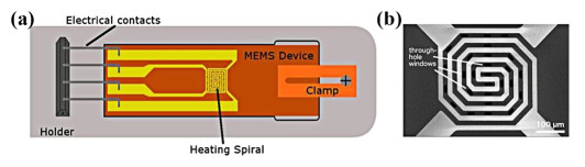
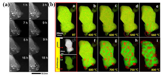
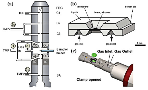
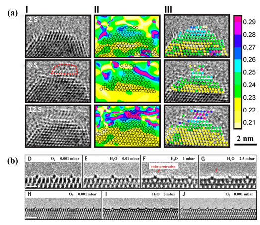
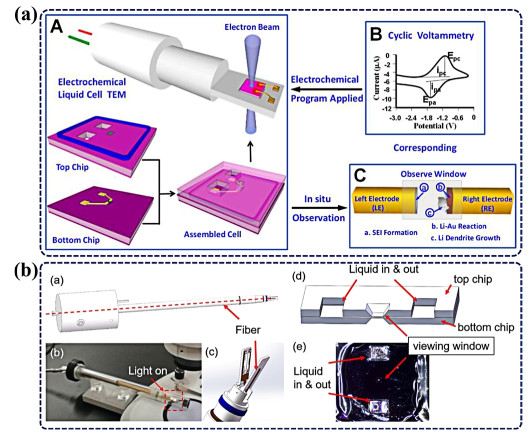
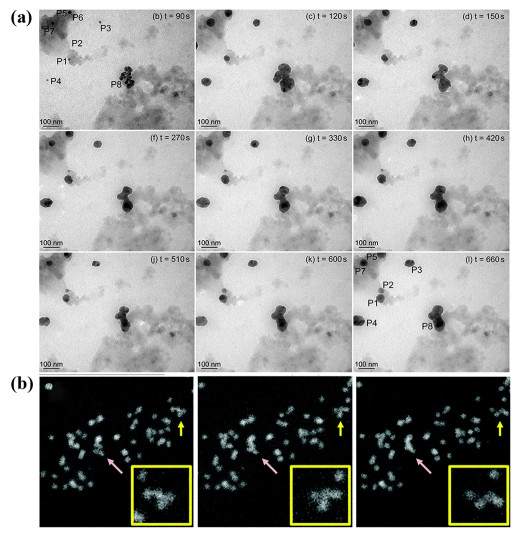
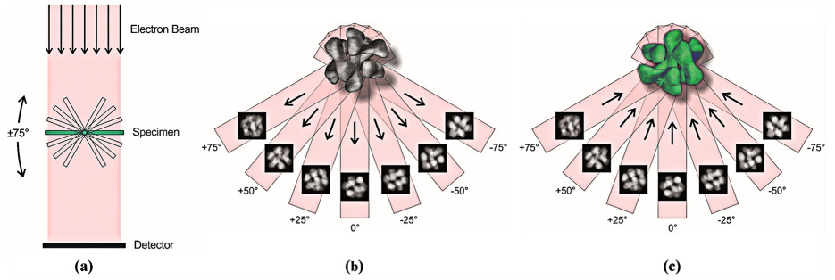
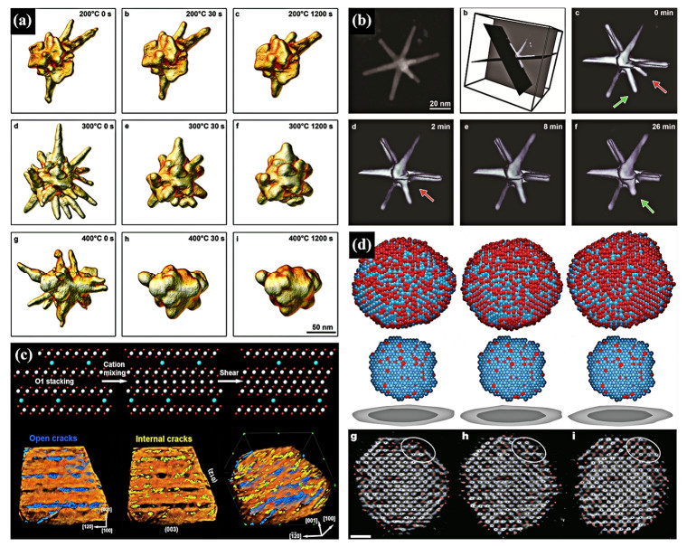
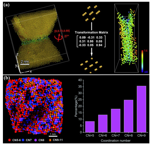
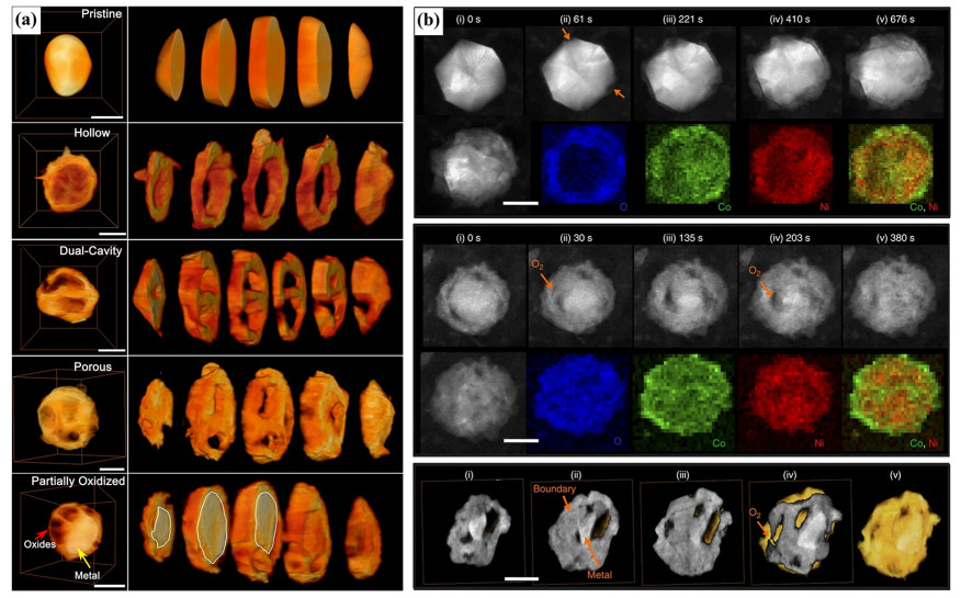
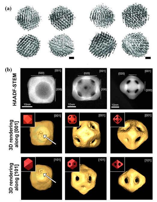
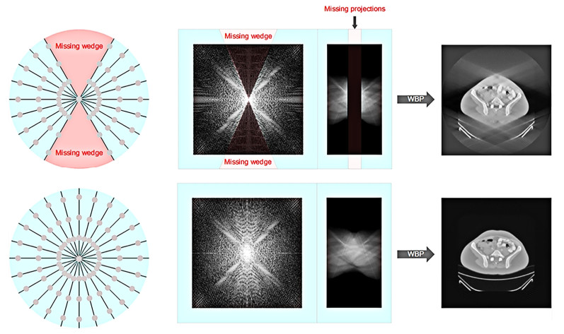
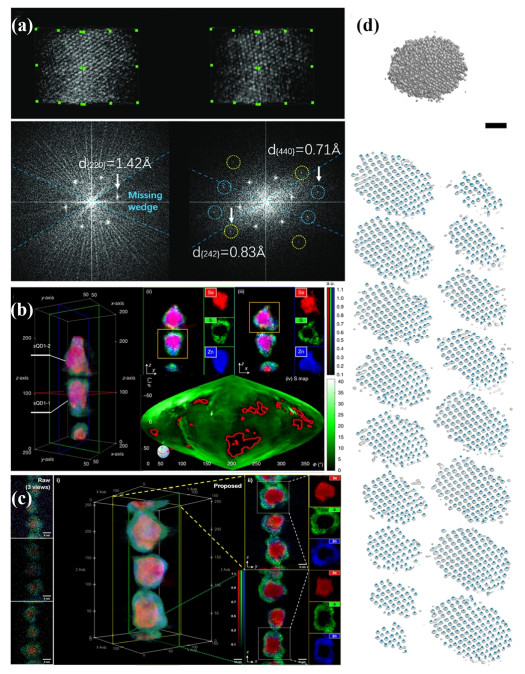


 扫一扫看文章
计量
- PDF下载量: 6
- 文章访问数: 2054
- HTML全文浏览量: 63
