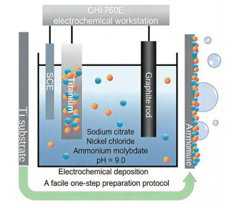
Scheme 1.
Schematic illustration of the synthesis process of Mo-Ni alloy self-supported electrodes

In situ construction of Mo-Ni alloy self-supported electrodes via one-step electrochemical deposition for efficient electrocatalytic hydrogen evolution
Yuanyuan TIAN , Xiaofang MA , Xinyi LI , Jianjun ZHANG , Ruixue TIAN


Fossil energy holds a dominant position in the global energy consumption structure. Nevertheless, its intrinsically high carbon emissions and pollutant generation significantly impede the attainment of the "dual carbon" goals. As a secondary clean energy carrier with ultra-high energy density[1], hydrogen energy features zero pollution and zero carbon emissions during utilization. Electrochemical hydrogen production through catalysis is remarkable for its outstanding controllability, operational stability, high-purity products, and pollution-free processes[2-4]. Moreover, the necessary electricity can be obtained from renewable energy sources, which allows for full-life-cycle carbon neutrality. However, the commercialization of electrocatalytic hydrogen evolution reaction (HER) is mainly constrained by the performance, stability, and cost of key components, particularly the electrodes[5-8]. Specifically, the high material costs of precious metal catalysts and the complexity of the secondary electrode fabrication process are the primary drivers of elevated overall costs, whereas the catalytic activity and long-term stability of the electrodes also impose non-negligible limitations. Consequently, integrating catalyst design with electrode fabrication and adopting self-supported electrode architecture are widely regarded as the optimal strategies for achieving a highly stable and cost‑effective electrocatalytic hydrogen evolution process.
Transition metal-based non-noble catalysts, characterized by incompletely filled d-orbitals and broad band structures, exhibit distinct physicochemical properties that endow them with intrinsic catalytic activity, thus rendering them versatile for electrocatalytic applications[9-10]. More significantly, Ni- and Mo-based non-noble metallic systems feature ample reserves and low expenses versus Pt and Rh noble metals, endowing inherent merits for developing low-cost hydrogen evolution electrodes with excellent catalytic activity. Previous investigations have corroborated that alloying two or more transition metals modulates the filling state of d-orbitals and regulates the overall electron cloud distribution, which are key electronic structure modifications that directly enhance HER performance[11-12]; specifically, when Ni is alloyed with other transition metals, this d-orbital modulation tailors the electronic configuration of Ni active sites, and by stabilizing the surface chemical state of these active centers, such tailoring in turn alleviates catalyst deactivation induced by oxide or hydride formation during HER[13-15]. Notably, Mo stands out as a particularly effective alloying constituent in this scenario because its half-filled d-orbitals can synergistically couple with the d-electrons of Ni and other transition metals[16-17]—an interaction rooted in the strong orbital overlap and electron delocalization inherent to transition metal alloys[18]; this d-orbital synergy not only optimizes the hydrogen adsorption energy to comply with the Sabatier principle but also facilitates the adsorption and dissociation of water molecules, thereby effectively addressing the rate‑limiting Volmer step in alkaline HER[19-20]. For Mo-Ni alloys specifically, this synergistic effect is further amplified by the formation of sub-nanoscale negative-excess-energy interfaces (NEIs) during the alloying process[21], as these NEIs enhance electron localization adjacent to active sites, stabilize the interfacial structure, and improve water dissociation kinetics.
In this work, the alloy catalyst strategy was innovatively integrated with the fabrication technology of binder-free self-supported electrodes, and a Mo-Ni alloy self-supported electrode was in situ constructed on Ti foil via a one-step electrochemical deposition process. Comprehensive characterizations, including microscopic morphology, crystal structure, and composition analyses, combined with HER performance evaluations, revealed that the as-prepared Mo-Ni electrodes remarkably accelerated interfacial HER kinetics. Specifically, the electrode deposited for 15 min achieved a current density of 10 mA·cm-2 at an overpotential of merely 107 mV in pure water and 95 mV in a simulated seawater environment. This study demonstrates that optimizing catalytic activity via regulated electrochemical deposition provides a novel strategy for developing efficient, stable, and low-cost electrocatalytic materials.
Sodium citrate dihydrate (C6H5Na3O7·2H2O) was acquired from Tianjin No.3 Chemical Factory Co., Ltd., ammonium molybdate tetrahydrate ((NH4)6Mo7O24·4H2O) was acquired from Tianjin Dingshengxin Chemical Co., Ltd., nickel chloride hexahydrate (NiCl2·6H2O) was acquired from Tianjin Beichen Fangzheng Reagent Factory, sodium chloride (NaCl) was acquired from Tianjin Shentai Chemical Reagent Co., Ltd., aqueous ammonia (NH3·H2O) was acquired from Shanghai Macklin Biochemical Co., Ltd., and anhydrous ethanol (C2H5OH) as well as potassium hydroxide (KOH) was acquired from Shandong Keyuan Biochemical Co., Ltd. Ti foils (300 mm×200 mm×0.2 mm) were purchased from Zhongnuo New Materials (Beijing) Technology Co., Ltd. Deionized water was self-prepared using an ultrapure water system (Economic-RO15). All chemicals were used as received without further purification.
The synthesis of Mo-Ni alloy self-supported electrodes is illustrated in Scheme 1. Electrochemical deposition was performed on a CHI 760E electrochemical workstation. A saturated calomel electrode (SCE) served as the reference electrode, a graphite rod as the counter electrode, and the pre-treated Ti foil as the working electrode within a conventional three‑electrode configuration. The plating bath contained 0.2 mol·L-1 NiCl2·6H2O, 7 mmol·L-1 (NH4)6Mo7O24·4H2O, 0.3 mol·L-1 sodium citrate, and 0.3 mol·L-1 NaCl dissolved in ultrapure water. The pH was adjusted to approximately 9.0 using aqueous ammonia. Electrochemical deposition was carried out at a constant potential of -1.6 V (vs SCE) for 3, 5, 10, 15, and 20 min. The as-prepared self-supported Mo-Ni alloy (Mo-Ni/Ti) electrodes with different deposition durations were denoted as Mo-Ni/Ti-3, Mo-Ni/Ti-5, Mo-Ni/Ti-10, Mo-Ni/Ti-15, and Mo-Ni/Ti-20, respectively.
The microstructure, chemical composition, and elemental valence states of the fabricated composite electrodes were examined by scanning electron microscopy (SEM, JSM-7800F) and X-ray photoelectron spectroscopy (XPS, Thermo ESCALAB 250Xi). Phase identification and elemental analysis were carried out via X-ray diffraction (XRD, MiniFlex 600) over a 2θ range of 10°-90° at a scanning rate of 10 (°)·min-1, with the instrument operated at 40 kV and 30 mA using Cu Kα radiation (λ=0.154 06 nm). Inductively coupled plasma atomic emission spectroscopy (ICP-AES) was performed using a Thermo ICP OES7200 (Thermo Fisher, USA).
The electrocatalytic HER activity of the Mo-Ni/Ti electrodes was evaluated in a conventional three‑electrode cell using a CHI 760E workstation. The Mo-Ni/Ti electrodes served as the working electrode, a saturated calomel electrode (SCE) as the reference, and a graphite rod as the counter electrode. Measurements were carried out in an alkaline aqueous solution (1 mol·L-1 KOH) and a simulated seawater solution (1 mol·L-1 KOH+0.5 mol·L-1 NaCl). Linear sweep voltammetry (LSV) was recorded from 0 to -0.5 V (vs RHE) at a scan rate of 10 mV·s-1. Electrochemical impedance spectroscopy (EIS) was carried out at an overpotential of -100 mV with a 5 mV AC perturbation over a frequency range of 105 to 10-1 Hz. Double-layer capacitance was determined by cyclic voltammetry (CV) at scan rates of 60, 80, 100, 120, and 150 mV·s-1 within -0.05 to 0.05 V (vs RHE), enabling estimation of the electrochemically active surface area. Long-term HER stability was assessed by chronoamperometry for 3 600 s at current densities of 10, 20, 50, and 100 mA·cm-2.
Fig.1 presents the SEM images of the Mo-Ni/Ti electrodes fabricated via electrochemical deposition. These electrodes were characterized by a thin-film microstructure composed of densely packed spherical particles with diameters in the range of hundreds of nanometers. Moreover, even smaller secondary structures exist on the surface of these nanospheres. At a deposition duration of 3 min (Fig.1a), the electrode surface showed relatively dense small crystalline particles with uniform distribution, and the particle diameter was approximately 200 nm. When the deposition time was extended to 5, 10, and 15 min (Fig.1b-1d), the surface grains grew gradually, with the particle diameter increasing to around 700 nm and the grains extruding and fusing. For the electrode deposited for 20 min (Fig.1e), the surface became rough, with distinct cracks formed between bulk structures. This phenomenon indicates that as the crystalline particles grew, the interfacial stress between the thin film and the Ti substrate accumulated gradually. Eventually, the stress concentration at grain boundaries leads to the degradation of active components[22-23].
To further identify the chemical elements and their distribution on the electrode surface, energy‑dispersive X-ray spectroscopy (EDS) characterization was performed. Fig.1f-1h display the EDS elemental mapping images of the Mo-Ni/Ti-15 electrode, clearly revealing the uniform distribution of Ni, Mo, and O elements across the entire test area. The EDS spectrum (Fig.1i) showed that the atomic ratio of Ni, Mo, and O was approximately 6∶2∶3. The elemental composition of the electrode was further verified through ICP measurements, as presented in Table S1 (Supporting information). This finding further confirms the successful loading of the Mo-Ni alloy catalyst on the Ti substrate, with a certain degree of oxidation inevitably present on the surface.

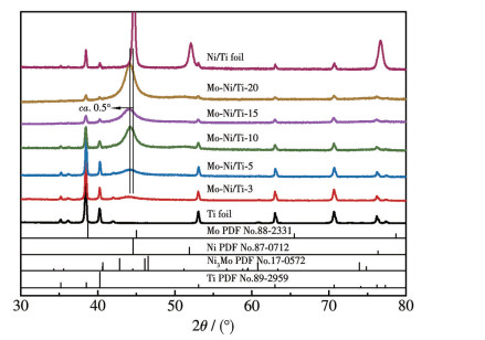
The crystal structure evolution of the electrodes fabricated with different electrochemical deposition durations was systematically investigated via XRD. To enable a more precise comparative analysis of the crystal structure, a pure Ni/Ti foil electrode was prepared following an identical synthesis protocol, and its XRD pattern was recorded under consistent experimental conditions. By comparison with standard PDF cards, the characteristic diffraction peaks observed at 35.08°, 38.42°, and 40.16° were indexed to the (100), (002), and (101) crystal planes of the Ti substrate (PDF No. 89-2959), respectively. All tested electrodes exhibited distinct diffraction peaks of metallic Ti, demonstrating that the metallic Ti substrate retained its structural integrity without damage during the electrode preparation process. For the Ni/Ti foil contrast electrode, three intense and sharp diffraction peaks were detected at 44.50°, 51.85°, and 76.38°, which are consistent with the standard pattern of pure Ni (PDF No.87-0712) deposited on the Ti substrate. For the as-prepared Mo-Ni/Ti electrodes, the intensity of diffraction peaks increased, and the peak shape became sharper with increasing electrodeposition duration. Besides, the full width at half maximum (FWHM) of the diffraction peaks narrows as electrodeposition proceeds, indicating an increase in the crystallinity of the Mo-Ni alloy phase at the electrode interface. The diffraction peak positions differed from those characteristic of Ni3Mo (PDF No.17-0572), suggesting that the electrodeposited catalyst does not contain a Mo-Ni intermetallic phase. In addition, the diffraction peaks shifted slightly by approximately 0.5° versus pure Ni, and the corresponding FWHM values of the Mo-Ni electrode diffraction signals were wider than those of pure Ni. This phenomenon is attributed to the substitution of partial Ni atoms (125 pm) in the lattice by Mo atoms with a larger atomic radius (139 pm), which induces expansion of the original Ni lattice[24].
To further clarify the surface elemental composition and chemical states of the Mo-Ni/Ti-15 electrode, XPS measurements were conducted, and the corresponding results are displayed in Fig.3. Fig.3a presents the survey XPS spectrum of the Mo-Ni/Ti-15 electrode, where Mo, Ni, Ti, and O were clearly identified as coexisting elements on the electrode surface. For the high-resolution Ni2p spectrum (Fig.3b), the characteristic peaks at 860.96 and 879.65 eV correspond to the satellite peaks of Ni2+2p3/2 and Ni2+2p1/2, respectively. The peaks located at 856.01 and 873.88 eV are indexed to Ni2+2p3/2 and Ni2+2p1/2, which are ascribed to the inevitable oxidation of metals in the air[25-26]. Additionally, the peaks at 852.49 and 869.70 eV are confirmed as the characteristic peaks of metallic Ni0 in the Mo-Ni alloy[27]. For the high-resolution Mo3d spectrum (Fig.3c), the characteristic peaks at 227.71 and 229.99 eV verify the presence of metallic Mo0. Specifically, the peaks at 228.53 and 230.74 eV are assigned to Mo4+3d5/2 and Mo4+3d3/2, respectively. Those at 229.13 and 233.57 eV correspond to Mo5+3d5/2 and Mo5+3d3/2, respectively. The peaks at 232.09 and 235.22 eV are indexed to Mo6+3d5/2 and Mo6+3d3/2, respectively. The high-resolution O1s spectrum (Fig.3d) showed three distinct peaks at 530.12, 531.46, and 532.72 eV, which are attributed to M—O (M: metal) bonds, surface-adsorbed oxygen, and surface-adsorbed water molecules, respectively[28].
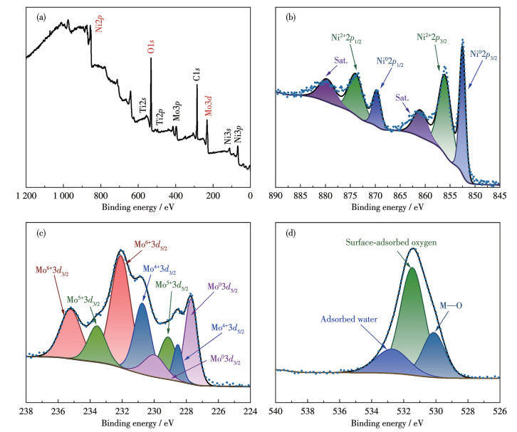
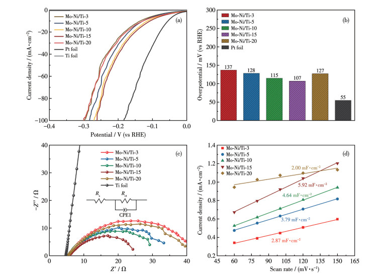
Fig.4 presents the electrocatalytic performance of the electrodes fabricated with varying electrodeposition durations. Fig.4a depicts the LSV curves of Mo-Ni/Ti, pure Pt foil, and pure Ti foil electrodes under alkaline test conditions. Fig.4b illustrates the bar chart of overpotentials corresponding to a current density of 10 mA·cm-2 for the tested electrodes. In the alkaline medium, the HER activities of electrodes prepared with different deposition durations were enhanced with prolonged electrodeposition time. Specifically, the Mo-Ni/Ti-15 electrode exhibited the optimal HER activity, with an overpotential of only 107 mV at a current density of 10 mA·cm-2. However, the Mo-Ni/Ti-20 electrode showed compromised HER performance, which may be ascribed to catalyst cracking at the electrode interface induced by excessive electrodeposition duration.
To further elucidate HER kinetics, EIS measurements were conducted on the various electrodes. As shown in Fig.4c, the Mo-Ni/Ti-15 electrode exhibited the lowest charge transfer resistance (Rct), which was significantly smaller than those of the other electrodes and the pure Ti foil. This confirms that the Mo-Ni/Ti-15 electrode possessed more efficient electron transfer capability and superior HER electrocatalytic activity. Fig.4d shows the double-layer capacitance (Cdl) values derived from CV curves of the tested electrodes at different scan rates in the non-Faradaic region. The Cdl serves as a reliable indicator for quantifying the relative electrochemically active surface area (ECSA) within the same testing system[29]. In the alkaline medium, the Cdl values of the Mo-Ni/Ti-3, Mo-Ni/Ti-5, Mo-Ni/Ti-10, Mo-Ni/Ti-15, and Mo-Ni/Ti-20 electrodes with deposition durations of 3, 5, 10, 15, and 20 min were 2.87, 3.79, 4.64, 5.92, and 2.00 mF·cm-2, respectively. This indicates that the Mo-Ni/Ti-15 electrode possesses a larger electrochemically active surface area. Thus, tuning the electrodeposition duration of the one-step fabrication strategy can expand the ECSA and lower the interfacial Rct of self-supported Mo-Ni electrodes. Such improvements modulate the intrinsic catalytic activity and boost the HER kinetics of the as-fabricated electrodes.
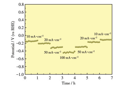
The electrochemical stability of the Mo-Ni/Ti-15 electrode was assessed via chronopotentiometry measurements at varying current densities in an alkaline electrolyte (Fig.5). At a current density of 10 mA·cm-2, the electrode potential fluctuated slightly around -0.12 V (vs RHE) with a small amplitude. Increasing the current density to 20 mA·cm-2 induced a negative shift in the electrode potential to approximately -0.21 V (vs RHE), which remained relatively stable thereafter. A further increase in current density to 50 mA·cm-2 led to a subsequent negative shift in the electrode potential to ca. -0.31 V (vs RHE). At a higher current density of 100 mA·cm-2, the electrode potential reached approximately -0.45 V (vs RHE). Despite noticeable fluctuations, no obvious potential decay trend was detected, indicating that the electrode retained considerable stability even under high-current-density operating conditions. Subsequently, when the applied current density was stepped back along the original sequence to 50, 20, and 10 mA·cm-2, the voltage plateaus exhibited by the electrode were consistent with those obtained in the initial stage, with an almost negligible fluctuation amplitude.
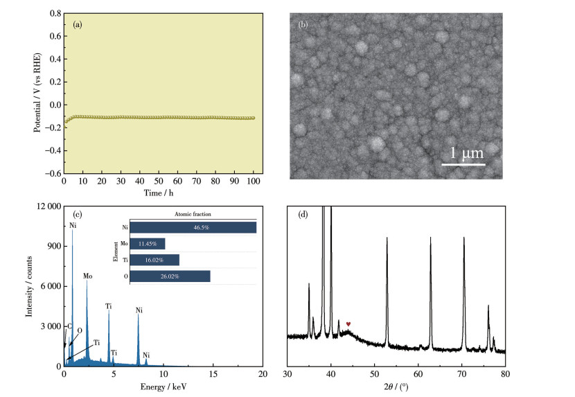
To further validate the remarkable HER stability of the as-prepared Mo-Ni/Ti-15 electrode, a 100 h‑long-term durability test was performed, with results illustrated in Fig.6a.The post-test SEM image, EDS spectrum, and XRD pattern of the electrode are presented in Fig.6b-6d. Fig.6a displays the chronopotentiometric curve of the Mo-Ni/Ti-15 electrode at a current density of 10 mA·cm-2. After a brief activation period, the HER overpotential stabilized at roughly 110 mV throughout the entire 100 h test with no apparent decay. The post-test SEM image (Fig.6b) revealed that Mo-Ni alloy nanoparticles remained tightly immobilized on the electrode interface, retaining nearly the same morphology as the fresh sample. EDS elemental analysis (Fig.6c) verifies negligible compositional change before and after electrolysis. Meanwhile, the XRD pattern (Fig.6d) still showed the characteristic diffraction peak at 44.0° corresponding to the Mo-Ni solid solution phase. This demonstrates that the electrodeposited self-supported Mo-Ni alloy electrode delivers outstanding long-term HER stability.
Using identical measurement protocols, the HER performance of various electrodes was evaluated in the simulated seawater medium, as presented in Fig.S1. The HER activity of Mo-Ni alloy self-supported electrodes fabricated with different electrodeposition durations exhibited the same trend in simulated seawater as in alkaline electrolytes. Among these electrodes, the Mo-Ni/Ti-15 electrode delivered the optimal HER performance, characterized by the lowest overpotential at 10 mA·cm-2 (95 mV), the smallest charge transfer resistance, and the largest double-layer capacitance. The slight discrepancies in these data can be ascribed to enhanced solution conductivity originating from additional sodium chloride in simulated seawater. Stability tests conducted in simulated seawater (Fig.S2) confirm that the electrode retains superior HER stability across a range of current densities, a finding consistent with the results obtained in alkaline electrolytes.
A self-supported Mo-Ni alloy electrode was successfully fabricated via one-step electrodeposition, and its electrocatalytic performance toward the HER in alkaline and simulated seawater media was systematically investigated. SEM, XRD, and XPS confirmed the formation of a well-defined nanostructured Mo-Ni alloy with abundant nanoparticulate features at the electrode interface, while electrochemical characterizations validated that the synergistic effect between Mo and Ni species efficiently facilitates the HER process. After optimizing the electrodeposition parameters, the as‑prepared self-supported Mo-Ni electrode achieved a low overpotential of merely 107 mV to reach a current density of 10 mA·cm-2 in an alkaline medium and 95 mV in a simulated seawater system. Both wide-range current density tests and long-term galvanostatic durability measurements were conducted to evaluate electrode stability. Combined with post-test physical characterizations including SEM, EDS, and XRD, the results demonstrate that the as-prepared electrode possesses prominent electrocatalytic durability and excellent structural integrity during continuous HER operation. Overall, this facile one‑step electrodeposition strategy enables the scalable fabrication of high‑performance Mo-Ni self-supported electrodes. The merits of low cost, superior catalytic activity, and robust long-term stability make this non-noble metal electrode a promising candidate and provide a feasible reference for the future commercialization of water splitting hydrogen production.
Supporting information is available at
LIU X, WANG P, LIANG X, ZHANG Q, WANG Z, LIU Y, ZHENG Z, DAI Y, HUANG B. Research progress and surface/interfacial regulation methods for electrophotocatalytic hydrogen production from water splitting[J]. Mater. Today Energy, 2020, 18: 100524 doi: 10.1016/j.mtener.2020.100524
LI Z B, ZHONG H N, LIU X J, CHIANG F K, LI R, CHEN H W, WANG X Z, WAN C B, WU Y, WANG H, JIANG S H, ZHANG X B, LU Z P. Dynamic dissolution-deposition equilibrium enables unprecedented HER stability in acidic PEMWE[J]. Adv. Mater., 2025, 37: e10703 doi: 10.1002/adma.202510703
ZHOU B Y, MAO Y Q, ZHANG H J, WU C C, LI J D, LIU X J. Heterostructure design-induced electric field engineering toward promoted alkaline HER catalysis[J]. Chem. Eng. J., 2025, 523: 168708 doi: 10.1016/j.cej.2025.168708
CHOI S, KWON J, KIM J, SUN J, PARK C, JAMESON G, KIM J H, PAIK U, SONG T. Independent-active-site engineering in N: NiFeP@FeNC electrocatalyst for mitigating HER site oxidation in alkaline electrolysis[J]. Adv. Compos. Hybrid Mater., 2025, 8: 438-452 doi: 10.1007/s42114-025-01507-7
SMILJANIC M, PANIC S, BELE M, RUIZ-ZEPEDA F, PAVKO L, GASPARIC L, KOKAIJ A, GABERSCEK M, HODNIK N. Improving the HER activity and stability of Pt nanoparticles by titanium oxynitride support[J]. ACS Catal., 2022, 12: 13021-13033 doi: 10.1021/acscatal.2c03214
MA W S, ZHANG Y H, WANG B Y, WANG J C, DAI Y N, HU L W, LV X W, DANG J. Significantly enhanced OER and HER performance of NiCo-LDH and NiCoP under industrial water splitting conditions through Ru and Mn bimetallic Co-doping strategy[J]. Chem. Eng. J., 2024, 494: 153212 doi: 10.1016/j.cej.2024.153212
HE X Y, LI R M, LIU J Y, LIU Q, CHEN R R, SONG D L, WANG J. Hierarchical FeCo2O4@NiCo layered double hydroxide core/shell nanowires for high performance flexible all-solid-state asymmetric supercapacitors[J]. Chem. Eng. J., 2018, 334: 1573-1583 doi: 10.1016/j.cej.2017.11.089
SUN J Z, ETCHEVERRY L, BERGEL A. Revisiting basic assumptions of the hydrogen evolution reaction (HER) for water electrolysis at near-neutral pH[J]. Chem. Eng. J., 2025, 507: 160490 doi: 10.1016/j.cej.2025.160490
CAI N, FU J, CHAN V, LIU M M, CHEN W M, WANG J Z, ZENG H, YU F Q. MnCo2O4@nitrogen-doped carbon nanofiber composites with meso-microporous structure for high-performance symmetric supercapacitors[J]. J. Alloy. Compd., 2019, 782: 251-262 doi: 10.1016/j.jallcom.2018.12.044
FENG J Z, TANG R X, LIU G F, MENG T. Regulating d-orbital electronic character and HER free energy of VN electrocatalyst by anchoring single atom[J]. Chem. Eng. J., 2023, 452: 139131 doi: 10.1016/j.cej.2022.139131
LIU Q H, REN W J, ZHANG S W, HUANG Y, CHEN D L, ZENG W N, ZHOU Z C, HE L, GUO W P, LI J F. d-orbital reconstructions forced by double bow-shaped deformations and second coordination sphere effects of Cu(Ⅱ) heme analogs in HER[J]. Chem. ‒Eur. J., 2022, 28: 202103892 doi: 10.1002/chem.202103892
NADY H, EL-RABIEI M M, SAMY M, DEYAB M A, EI-HAFEZ G A. Novel Ni-Cr-based alloys as hydrogen fuel sources through alkaline water electrolytes[J]. Int. J. Hydrog. Energy, 2021, 46: 34749-34766 doi: 10.1016/j.ijhydene.2021.08.056
ASGHARI ALAMDARI A, JAHANGIRI H, YAGCI M B, IGARASHI K, MATSUMOTO H, MOTALLEBZADEH A, UGUR U. Exploring the role of Mo and Mn in improving the OER and HER performance of CoCuFeNi-based high-entropy alloys[J]. ACS Appl. Energy Mater., 2024, 7: 2423-2435 doi: 10.1021/acsaem.3c03227
FENG C, SHAO J X, WU H Y, HASSAN A, YANG H P, YU J Y, HU Q, HE C X. Ultra-high overpotential induces NiS2 deep reconstruction to significantly improve HER performance[J]. Chin. J. Catal., 2025, 72: 230-242 doi: 10.1016/S1872-2067(24)60286-X
ZHENG X N, YAO Y, WANG Y, LIU Y. Tuning the electronic structure of transition metals embedded in nitrogen-doped graphene for electrocatalytic nitrogen reduction: A first‑principles study[J]. Nanoscale, 2020, 12: 9696-9707 doi: 10.1039/D0NR00072H
DOU X Y, YUAN D, LIANG X P, SONG K P, HU R M, ZHANG L, ROY J C, JIANG X C, LIU H K, DOU Y H, YU L P. Synergy between Mo dopants and Ni vacancies in NiOOH for enhanced oxygen evolution reaction[J]. Chem. Eng. J., 2023, 468: 143715 doi: 10.1016/j.cej.2023.143715
ZHANG W D, XIAO Y X, LI L, YU Z C, FENG J X, ZHONG C C, IP W F, PAN H. Dynamic Mo leaching and vacancy engineering synergize HER and OER kinetics in NiFe-based catalysts for overall water electrolysis[J]. Mater. Horiz., 2025, 12: 10901-10910 doi: 10.1039/D5MH01366F
BUCCHERI B, GANCI F, PATELLA B, AIELLO G, MANDIN P, INGUANTA R. Ni-Fe alloy nanostructured electrodes for water splitting in alkaline electrolyser[J]. Electrochim. Acta, 2021, 388: 138588 doi: 10.1016/j.electacta.2021.138588
GUO F, ZHANG Z Y, CHEN R Z, TAN Y Y, WU W, WANG Z C, ZENG T, ZHU W B, LIN C X, CHENG N C. Dual roles of sub‑nanometer NiO in alkaline hydrogen evolution reaction: Breaking the Volmer limitation and optimizing d-orbital electronic configuration[J]. Mater. Horiz., 2023, 10: 2913-2920 doi: 10.1039/D3MH00416C
YANG L, ZHANG M, SHI M R, YAO Y, LIU Y, ZHOU J Q, CAO Y, LI Z, LIU M F, WANG X Z, GAN Z X, ZHANG H X, CHANG S, ZHOU G. Hierarchical porous P-doped NiCo alloy with α/ε phase-defect synergy to boost alkaline HER kinetics and bifunctional activity[J]. Nanomaterials, 2025, 15: 1562-1578 doi: 10.3390/nano15201562
LI J X, JIN Z H, LI X Y, LU K. Strengthening Ni alloys with nanoscale interfaces of negative excess energy[J]. Science, 2025, 389: 617-621
WANG L Y, LI X B, HU X C, CHEN S Y, QIU Z H, WANG Y F, ZHANG H, YU Y, YANG B, YANG Y, ORGIANI P, ARUTA C, YANG N. Grain boundary boosting the thermal stability of Pt/CeO2 thin films[J]. Nano Res., 2023, 16(2): 3278-3286 doi: 10.1007/s12274-022-4899-9
BELIAEV L Y, SHKONDIN E, LAVRINENKO A V, TAKAYAMA O. Optical properties of plasmonic titanium nitride thin films from ultraviolet to mid-infrared wavelengths deposited by pulsed-dc sputtering, thermal and plasma-enhanced atomic layer deposition[J]. Opt. Mater., 2023, 143: 114237 doi: 10.1016/j.optmat.2023.114237
DASTAFKAN K, WANG S, RONG C, MEYER Q, LI Y B, ZHANG Q, ZHAO C. Cosynergistic molybdate oxo-anionic modification of FeNi-based electrocatalysts for efficient oxygen evolution reaction[J]. Adv. Funct. Mater., 2022, 32: 2107342 doi: 10.1002/adfm.202107342
XIONG L, WANG B, CAI H, HAO H J, LI J, YANG T, YANG S C. Understanding the doping effect on hydrogen evolution activity of transition-metal phosphides: Modeled with Ni2P[J]. Appl. Catal. B‒Environ., 2021, 295: 120283 doi: 10.1016/j.apcatb.2021.120283
YUAN M, SUN Y, YANG Y, ZHANG J X, DIPAZIR S, ZHAO T K, LI S W, XIE Y B, ZHAO H, LIU Z J, ZHANG G J. Boosting oxygen evolution reactivity by modulating electronic structure and honeycomb-like architecture in Ni2P/N, P-codoped carbon hybrids[J]. Green Energy Environ., 2021, 6: 866-874 doi: 10.1016/j.gee.2020.07.012
ZHANG J, WANG T, LIU P, LIAO Z Q, LIU S H, ZHUANG X D, CHEN M W, ZSCHECH E, FENG X L. Efficient hydrogen production on MoNi4 electrocatalysts with fast water dissociation kinetics[J]. Nat. Commun., 2017, 8: 15437 doi: 10.1038/ncomms15437
LI Q, ZHANG K, LI X, HE J Q, LOU Y B, CHEN J X. Enhanced electrocatalytic performance of uniformly spherical Ni-MOF decorated with NiMoO4 nanorods for oxygen evolution reaction[J]. J. Alloy. Compd., 2022, 920: 165941 doi: 10.1016/j.jallcom.2022.165941
JOHNSON A. Electrochemical surface area (ECSA) evaluation in electrocatalysis: Principles, measurement techniques, and future perspectives[J]. J. Eng. Ind. Res., 2025, 6(3): 212-222

Scheme 1 Schematic illustration of the synthesis process of Mo-Ni alloy self-supported electrodes

Figure 1 SEM images of the Mo-Ni/Ti electrodes prepared via electrochemical deposition with different durations: (a) 3 min, (b) 5 min, (c) 10 min, (d) 15 min, and (e) 20 min; EDS characterizations of the Mo-Ni/Ti-15 electrode: (f-h) EDS elemental mapping images (scale bar: 500 nm) and (i) EDS spectrum (inset: corresponding atomic fractions)

Figure 2 XRD patterns of Ti foil, Ni/Ti foil, and Mo-Ni/Ti electrodes prepared via electrochemical deposition at different deposition durations

Figure 3 XPS spectra of the Mo-Ni/Ti-15 electrode: (a) survey; (b) Ni2p; (c) Mo3d; (d) O1s

Figure 4 Electrochemical test results of the electrodes prepared via electrochemical deposition at various deposition durations in the alkaline medium: (a) LSV curves, (b) overpotential bar charts at a current density of 10 mA·cm-2, (c) Nyquist plots (inset: an equivalent circuit diagram, where Rs represents the solution resistance, and CPE1 represents the constant phase element), and (d) Cdl plots

Figure 5 Chronopotentiometry curves of the Mo-Ni/Ti-15 electrode in the alkaline medium at current densities of 10, 20, 50, and 100 mA·cm-2

 扫一扫看文章


扫一扫关注我们
 下载:
 下载:

 下载: