Figure 1.
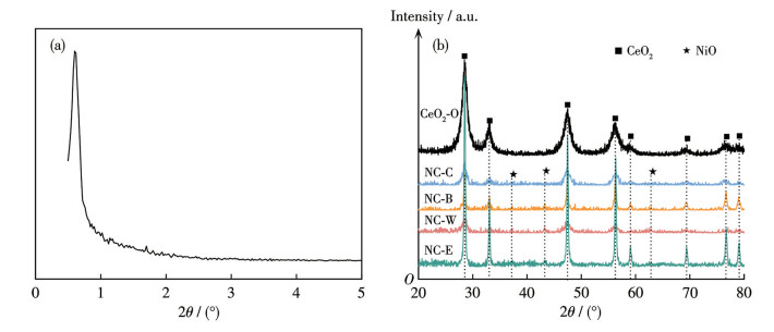
(a) Small-angle XRD pattern of CeO2-0 and (b) XRD patterns of the samples
Influence of the loading methods of Ni species in Ni/CeO2 catalysts on the performance of CO methanation
Runran WANG , Qiyue JIAO , Ruifang LI , Hong WANG , Hongwei WANG , Yali BAO , Qi WANG , Xiaoyan WANG

As the global energy structure transforms, the strategic importance of clean and low-carbon natural gas has become increasingly prominent[1-2]. CO methanation technology converts coal gasification syngas into synthetic natural gas, serving as a crucial bridge linking the coal chemical industry with clean energy[3-4]. This technology not only alleviates pressure on natural gas supply but also achieves clean and efficient conversion of coal resources, holding significant value in the energy and environmental sectors. Consequently, it has garnered considerable attention from both academic and industrial circles[5-6].
The core of CO methanation technology lies in developing high-performance catalysts. Although precious metal catalysts offer superior performance, their high cost limits widespread application[7-8]. Nickel (Ni)-based catalysts are widely used due to their high activity and low cost, but suffer from low-temperature deactivation and high-temperature sintering[9-10]. The performance of Ni-based catalysts is primarily governed by the dispersion, particle size of the active Ni component, and its interaction with the support[11-12]. For instance, Li et al.[10] investigated the effect of Ni particle size on CO methanation by preparing a series of Ni@Al2O3-n catalysts. The study revealed that catalysts featuring medium‑sized Ni nanoparticles exhibited high activity at 260 ℃, achieving complete CO conversion rate alongside excellent coking resistance. Xu et al.[13] prepared Ni/SiO2 catalysts via a combustion-impregnation method. By controlling the combustion process, they obtained small Ni particles with an average size of approximately 6 nm. Hydrogen temperature-programmed desorption (H2-TPD) characterization confirmed that this approach significantly improved Ni dispersion and enhanced reactant activation capacity, resulting in outstanding low-temperature activity and CH4 selectivity for CO2 methanation.
Mesoporous ceria (CeO2) demonstrates significant potential in catalysis due to its well-ordered pore structure, high specific surface area, tunable pore size, unique Ce4+/Ce3+ redox pair, and outstanding oxygen storage/release capabilities[14-16]. The well-defined mesoporous structure facilitates mass transfer and stabilizes loaded metal nanoparticles through spatial confinement, significantly enhancing catalytic performance by leveraging their small size and surface effects[17-19]. Furthermore, the strong interaction between CeO2 and metal components can further enhance the dispersion and stability of the active phase. However, current research has primarily focused on regulating Ni loading, CeO2 morphology, or adding additives, while the impact of the loading method—a critical parameter affecting Ni dispersion—remains understudied. Studies indicate that different loading methods alter the spatial distribution, particle size, and dispersion of Ni species within the structured channels, thereby influencing the catalyst′s methanation activity, selectivity, and sintering resistance[20]. Niu et al.[21] prepared two Ni/CeO2 catalysts using incipient wetness impregnation and combustion methods, respectively. The combustion method produced smaller, more highly dispersed NiO nanoparticles. The rapid, self-sustaining redox reactions during combustion effectively suppressed NiO migration and agglomeration, resulting in a catalyst with outstanding catalytic activity and stability for the dry reforming of methane (DRM). Chen et al.[22] prepared three Ni/SiO2 catalysts using ammonia evaporation, impregnation, and sol-gel methods. It was found that the catalyst prepared by ammonia evaporation had smaller Ni particles, stronger metal-support interaction, and abundant Ni‑O‑Si units on its surface, which significantly improved the catalyst′s anti-sintering performance. However, the catalyst prepared by impregnation had poor catalytic performance due to the uneven distribution of nickel species, large particles, and weak metal-support interaction.
Therefore, this study aims to investigate the influence of different loading methods on the microstructure and CO methanation performance of Ni catalysts supported on mesoporous CeO2. By systematically comparing the structure-activity relationships of Ni/CeO2 catalysts synthesized via three distinct methods, this work elucidates how loading methods precisely regulate key structural parameters—such as Ni species dispersion and particle size—to determine macroscopic catalytic performance, including low-temperature activity, selectivity, and long-term coking resistance. These findings provide crucial theoretical foundations and experimental support for designing next-generation, highly efficient, and stable industrial methanation catalysts.
Nickel nitrate hexahydrate (Ni(NO3)2·6H2O, AR), cerium nitrate hexahydrate (Ce(NO3)3·6H2O), bis(cyclopentadienyl)nickel (AR), citric acid monohydrate (AR), and hexadecyl trimethyl ammonium bromide (CTAB, AR) were purchased from Shanghai Titan Technology Co., Ltd., China.
Ce(NO3)3·6H2O, citric acid, and CTAB were mixed in a molar ratio of 5∶1∶1 under continuous stirring. Ammonia solution was slowly added to adjust the system pH to 9. The mixture was stirred in a water bath for 2 h, then transferred to a polytetrafluoroethylene-lined high-pressure reactor and crystallized at 120 ℃ for 12 h. The product was filtered and washed three times alternately with anhydrous ethanol and distilled water, and dried in a forced-air oven for 12 h. Finally, it was calcined in a muffle furnace at 300 ℃ for 5 h (heating rate: 5 ℃·min-1 to obtain pale yellow mesoporous CeO2 powder, designated as CeO2-0.
The obtained CeO2-0 was calcined at 1 000 ℃ for 4 h in a muffle furnace (heating rate: 5 ℃·min-1). The resulting reference sample was designated as CeO2-1.
For a nominal NiO loading (mass fraction) of 20%, the corresponding amount of Ni(NO3)2·6H2O was weighed and dissolved in 100 mL of distilled water (or anhydrous ethanol) to prepare the impregnation solution. Then, 2 g of the prepared mesoporous CeO2-0 support was weighed. The incipient wetness impregnation method was applied by adding the solution dropwise to the support. After ultrasonic-assisted impregnation at room temperature for 24 h, the sample was dried in a forced-air oven at 80 ℃ for 24 h. Subsequently, it was calcined at 550 ℃ for 4 h (heating rate: 1 ℃·min-1), yielding catalysts with 20% NiO loading, designated as NC-W and NC-E (W denoted deionized water as the dispersant, E denoted anhydrous ethanol as the dispersant).
Following the same procedure as in section 1.2.1, but using the prepared CeO2-1 support. An equal volume of the prepared Ni(NO3)2·6H2O solution dissolved in ethanol was added to the support using the volume-equivalent impregnation method. After ultrasonic impregnation at room temperature for 24 h, the sample was dried in a forced-air drying oven at 80 ℃ for 24 h. After removal, the sample was calcined at 550 ℃ for 4 h (heating rate of 1 ℃·min-1), yielding a reference catalyst with 20% NiO loading (designated as NC-1).
1.644 g of bis(cyclopentadienyl)nickel and 2 g of the prepared mesoporous CeO2-0 support were placed into a quartz reaction tube. Under vacuum, the mixture was heated at 1 ℃·min-1 to 120 ℃ and held for 24 h. After cooling to room temperature, the sample was dissolved in ethanol, magnetically stirred for 4 h, centrifuged, washed, dried overnight, and finally calcined in a muffle furnace at 500 ℃ for 4 h (heating rate: 1 ℃·min-1) to obtain the catalyst, designated as NC‑B, where B denoted bis(cyclopentadienyl)nickel sublimation loading[23].
A stoichiometric ratio control method was adopted. The dosage of Ni(NO3)2·6H2O was calculated based on 20% NiO loading in the final product. Ce(NO3)3·6H2O, Ni(NO3)2·6H2O, citric acid, and CTAB were weighed in a molar ratio of 5.2∶3∶1∶1, and homogeneous mixing of the precursor system was achieved under continuous stirring. Ammonia solution was added dropwise until the system pH reached 9. The mixture was stirred in an 80 ℃ water bath for 2 h, then transferred to a polytetrafluoroethylene-lined high-pressure reactor and crystallized at 120 ℃ for 12 h. The product was vacuum-filtered, and the precipitate was washed alternately three times with anhydrous ethanol and distilled water, followed by drying for 12 h. Calcination was performed in a muffle furnace: first at 300 ℃ for 5 h (heating rate: 1 ℃·min-1), then at 550 ℃ for 4 h (heating rate: 1 ℃·min-1). The resulting catalyst powder was designated NC-C (C denoted the co-precipitation method).
X-ray diffractometer (XRD) patterns were recorded on a Bruker D8 X-ray diffractometer using Cu Kα radiation (λ=0.154 06 nm) operated at 40 kV and 100 mA. Data were collected in a 2θ range of 5° to 90° with a step size of 3 (°)·min-1. A Rigaku D/MAX-2500/PC X-ray diffractometer was used for small-angle XRD analysis in the range of 0.5° to 5° with a step size of 1 (°)·min-1. Crystallite sizes were estimated using the Scherrer equation:
|
|
(1) |
where D is the crystallite size (nm), K is the Scherrer constant (0.89), λ is the X-ray wavelength (0.154 nm), and β is the full width at half maximum (FWHM).
X-ray photoelectron spectroscopy (XPS) analysis was performed on a PHI 5000 VersaProbe Ⅱ X-ray photoelectron spectroscopy (Japan) using monochromatic Al Kα radiation (hν=1 486.1 eV) with an energy resolution of 50 eV. The binding energy was calibrated using the C1s peak at 284.6 eV to analyze the elemental composition and valence states of the samples.
Transmission electron microscope (TEM) and high-resolution transmission electron microscopy (HRTEM) images were obtained using a JEM-2010HR transmission electron microscope (JEOL, Japan) operated at 200 kV with a point resolution of 0.23 nm. The sample powder was ultrasonically dispersed in anhydrous ethanol, and a drop of the suspension was deposited onto a carbon-coated copper grid, dried, and observed under vacuum to examine morphology, pore structure, and the distribution and size of Ni nanoparticles.
N2 adsorption-desorption isotherms were measured at -196 ℃ using a Micromeritics ASAP-2020 analyzer. Before testing, samples underwent vacuum degassing pretreatment at 200 ℃, followed by static nitrogen adsorption at -196 ℃ (liquid nitrogen). Specific surface area was calculated using the Brunauer-Emmett-Teller (BET) method. Pore volumes and pore size distributions were derived from the adsorption branch using the Barrett-Joyner-Halenda (BJH) model.
Hydrogen temperature-programmed reduction (H2-TPR) experiments were conducted on a PX200 apparatus. Approximately 50 mg of catalyst (80 mesh) was loaded into a U-shaped quartz reactor. The sample was first purged with N2 at room temperature for 30 min. The gas was then switched to a H2/Ar mixture (1∶9, V/V), and the temperature was ramped from room temperature to 900 ℃ at a rate of 10 ℃·min-1.
Catalytic performance was evaluated using a WFSM-3060-DL fixed-bed reactor system (Tianjin Xianquan Co., Ltd.). Product analysis was performed online using an SP-2100A gas chromatograph (Beijing Beifeng Ruili Co., Ltd.) equipped with a thermal conductivity detector (TCD).
Typically, 0.3 g of catalyst (60-80 mesh) was loaded into the reactor. Before reaction, the sample was purged with nitrogen for 10 min, then reduced at 500 ℃ for 1 h under a high-purity H2 atmosphere. The temperature was subsequently lowered to 200 ℃ under the same H2 atmosphere before switching to a mixed gas (CO/H2/Ar, 18∶54∶28, V/V). The temperature was raised to 800 ℃ at a rate of 10 ℃·min-1. Products were collected and analyzed simultaneously at 50 ℃ intervals from 200 to 800 ℃.
In the gas chromatography (GC) analysis, Ar was used as the carrier gas. The support gas was Ar at a flow rate of 30 mL·min-1. The thermal conductivity detector (TCD) was set at 150 ℃. The column was TDX-01, the column oven temperature was set at 130 ℃, the injector temperature was set at 130 ℃, the pre-column pressure was set at 0.2 MPa, and the make-up pressure was set at 0.15 MPa.
The activity calculation formula is as follows:
|
|
(2) |
|
|
(3) |
|
|
(4) |
where XCO,
Fig.1a shows the small-angle XRD pattern of the CeO2-0 support prepared by hydrothermal synthesis. A distinct characteristic diffraction peak at 2θ≈0.8° corresponds to mesoporous materials[24], confirming the mesoporous structure of the CeO2‑0 support. Fig.1b showed that all samples exhibited characteristic diffraction peaks corresponding to the cubic fluorite structure of CeO2. The CeO2 diffraction peaks for NC‑E were more intense and sharper. This is attributed to the successful encapsulation of most NiO species within the mesoporous channels of CeO2, which ensures the high dispersion of NiO and also promotes the formation of long-range lattice order in the CeO2 framework during calcination, resulting in the significantly enhanced and sharper diffraction peaks observed in the NC‑E sample[25].
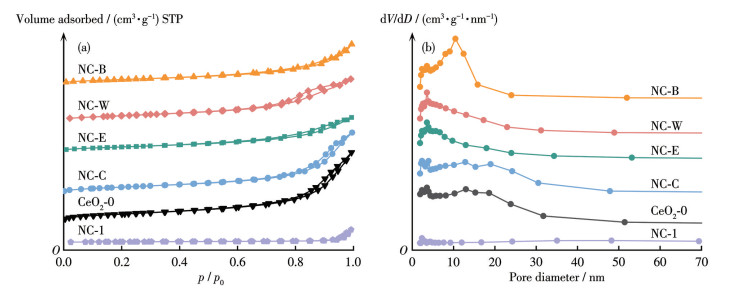
Fig.2 presents the N2 adsorption‑desorption isotherms and corresponding pore size distributions for the CeO2-0 support, NC-C, NC-B, NC-W, and NC-E. As shown in Fig.2a, all samples exhibited type Ⅳ isotherms with H3-type hysteresis loops[26], further confirming that CeO2-0 is a typical mesoporous material, consistent with the small-angle XRD results. This also indicated that loading metallic Ni did not alter the mesoporous structure of the support. The H3-type hysteresis loops at high relative pressures (p/p0>0.75) suggest the presence of slit-shaped pores[27-28]. The BJH pore size distribution curves in Fig.2b reveal that the mesopores of the CeO2-0 support were mainly concentrated in the 3-5 nm and 7-8 nm ranges. The pore sizes of NC-C, NC-B, NC-W, and NC-E were primarily distributed between 5 and 15 nm, indicating the presence of stacked pore channels and distinct mesoporous characteristics[29]. Furthermore, as listed in Table 1, NC-C, NC-B, NC-W, and NC-E retained high specific surface areas inherited from the support. This increased surface area facilitates the dispersion of Ni species, thereby enhancing catalytic performance.
 下载:
导出CSV
下载:
导出CSV
| Catalyst | Crystallite size of CeO2/nm | Mesoporous content/% | SBETa/(m2·g-1) | |
| CeO2⁃0 | 7.0 | 62.78 | 147 | — |
| NC⁃C | 9.0 | 92.4 | 104 | 34.61 |
| NC⁃B | 12.0 | 95.04 | 107 | 37.22 |
| NC⁃E | 28.3 | 86.84 | 91 | 28.33 |
| NC⁃W | 35.4 | 93.46 | 91 | 28.02 |
| NC⁃1 | — | 65.08 | 9 | — |
Table 1 lists the average particle sizes of each catalyst calculated using the Scherrer equation. The results showed that the average particle size of all catalysts was larger than that of the pure CeO2-0 support. After secondary calcination, the particle sizes of the samples increased.
The H2-TPR results in Fig.3a revealed that the mesoporous CeO2-0 support exhibited reduction peaks at approximately 500 and 790 ℃, attributed to the reduction of surface-adsorbed oxygen and bulk lattice oxygen, respectively. The surface oxygen species on CeO2-0 enhance the electron transfer capacity on the catalyst surface, thereby boosting catalytic activity[30]. The large peak area for surface oxygen reduction indicates an abundance of surface oxygen species, making CeO2-0 an ideal support for Ni-based methanation catalysts.
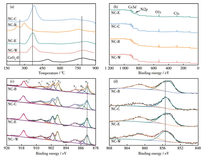
Reduction peaks above 700 ℃ are attributed to the CeO2-0 support. The reduction curves of NC-E and NC-W were similar, both exhibiting reduction peaks corresponding to weakly interacting NiO species at approximately 260 and 375 ℃. Combined with XRD particle size analysis, NC-W exhibited increased particle size after reduction and significantly smaller reduction peak areas, indicating encapsulation of NiO by the support, which reduces the amount of reducible NiO species. The H2-TPR results demonstrated that different preparation methods significantly influenced the morphologies of NiO species and their interaction strength with the CeO2-0 support.
The reduction curves of catalyst NC-B exhibited peaks at approximately 240 and 300 ℃, attributed to α-NiO with weak interactions with the support[31]. Compared to other catalysts, the reduction peaks of NC-B shift to lower temperatures, indicating abundant NiO species with weaker support interactions, leading to the formation of highly dispersed Ni nanoparticles that provide more active sites. In contrast, NC-C showed a NiO reduction peak only at 380 ℃, the highest temperature among all catalysts, indicating strong NiO-CeO2 interactions. The reduced Ni species in NC-C also maintained strong interactions with the support, enhancing their resistance to sintering.
Fig.3b shows the XPS survey spectra of the samples, indicating that the sample primarily composed of Ce, Ni, O, and C elements. Further systematic analysis of the XPS spectra of Ce3d and Ni2p was conducted to clarify the chemical states of the elements. Fig.3c shows the Ce3d XPS spectra of the samples. Due to hybridization between the Ce4f and O2p orbitals, the Ce3d XPS spectra exhibited a complex structure. Through fitting analysis, these spectra can be resolved into eight characteristic peaks, located at binding energies of approximately v0 (882.9 eV), u0 (885.7 eV), v1 (888.6 eV), v2 (897.7 eV), v0′ (901.1 eV), u0′ (903.8 eV), v1′ (907.6 eV), and v2′ (916.7 eV). Among these, u0 and u0′ belong to Ce3+, while v0, v1, v2, v0′, v1′, and v2′ belong to Ce4+. The peaks v2, v1, u0, and v0 at binding energies of 897.7, 888.6, 885.7, and 882.9 eV, respectively, are attributed to the ground state levels of Ce3d5/2. The peaks v2′, v1′, u0′, and v0′ at binding energies of 916.7, 907.6, 903.8, and 901.1 eV correspond to the ground state levels of Ce3d3/2[32]. Among catalysts prepared under different loading methods, the binding energy of Ce3d5/2 was uniformly 888.3 eV. As indicated by the molar ratio of Ce3+ to Ce3+ and Ce4+ [
Fig.3d shows the XPS spectra of the Ni2p for the samples. The binding energy of Ni2p3/2 was 855.8 eV, observed within the range of 855.5-856.5 eV, corresponding to the Ni2+ species. The peak at 861.0 eV is attributed to a satellite peak[33]. The Ni2+ peak area across the four catalysts indicates that the NC-C catalyst contained lower NiO content on its surface. Combined with H2-TPR and XRD characterization results, it is inferred that under these conditions, a significant amount of Ni2+ enters the CeO2 lattice, forming strongly interacting Ni-Ce solid solutions with CeO2.
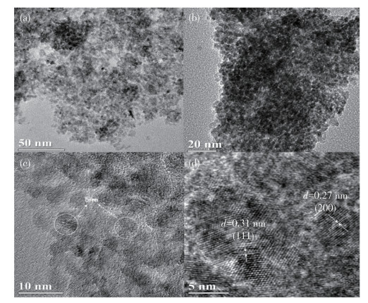
Fig.4 and 5 show TEM and HRTEM images of the CeO2-0 support and catalysts. As seen in Fig.4a and 4b, although some agglomeration existed, the CeO2 particles showed a relatively uniform size distribution. According to the statistical results in Fig.4c, the particle size distribution was primarily centered around 5 nm, consistent with BJH pore size distribution and small-angle XRD results. The HRTEM image in Fig.4d reveals lattice fringes with spacings of approximately 0.27 and 0.31 nm, corresponding to the (200) and (111) crystal planes of CeO2, respectively, indicating that these were the primary exposed surfaces of the mesoporous CeO2-0[34].
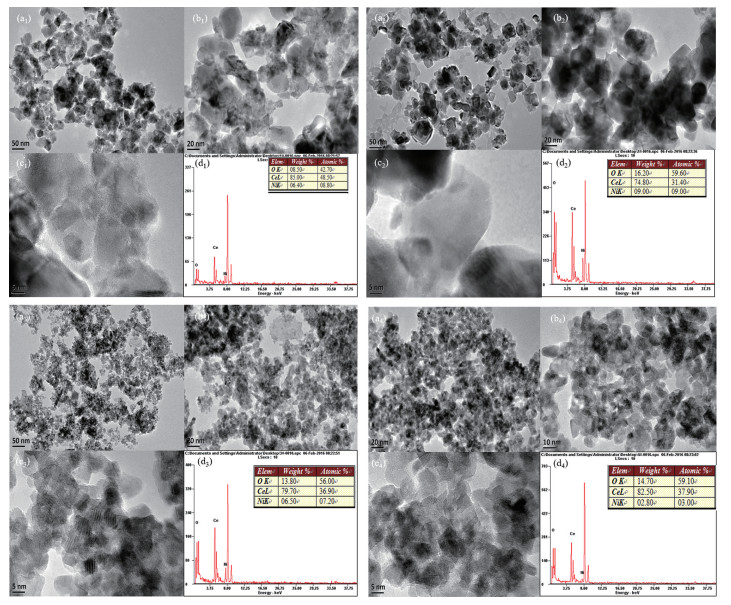
Inset: elemental contents.
TEM images of the catalysts in Fig.5a1 and 5b1 reveal significant agglomeration of particles in NC-W compared to the support, with sizes ranging from approximately 20 to 40 nm, consistent with XRD particle size analysis. Fig.5c1 showed NiO located at the interfaces between CeO2 particles. Combined with XRD analysis, this indicates that Ni species had entered the CeO2 lattice, leading to increased particle size. Fig.5a2 and 5b2 showed that NiO was uniformly dispersed throughout the NC-E sample. Furthermore, the HRTEM image in Fig.5c2 suggested that most NiO had entered the CeO2 channels and was confined within the mesopores. Fig.5a3 and 5b3 revealed that NC-B exhibited a worm-like mesoporous structure similar to the CeO2-0 support, with a uniform particle size distribution of approximately 8-13 nm. Fig.5c3 showed that NiO had extensively penetrated the support without causing agglomeration. Energy dispersive X-ray spectroscopy (EDX) analysis of the selected region in Fig.5d3 confirmed uniform Ni distribution on the CeO2-0 support. NC-C exhibited a uniform particle size distribution between 7-12 nm while maintaining an intact mesoporous structure (Fig.5a4 and 5b4). Fig.5c4 demonstrated uniform dispersion of NiO, attributed to more homogeneous atomic mixing achieved via the coprecipitation method. Fig.5d4 showed a surface Ni content (mass fraction) of only 2.80%, significantly lower than that of catalysts prepared by other methods (Fig.5d1-5d3), indicating substantial Ni dispersion within the support. Combined with H2-TPR results, it is evident that this Ni exhibits strong interactions with the support, with some Ni species likely incorporated into the CeO2 lattice.
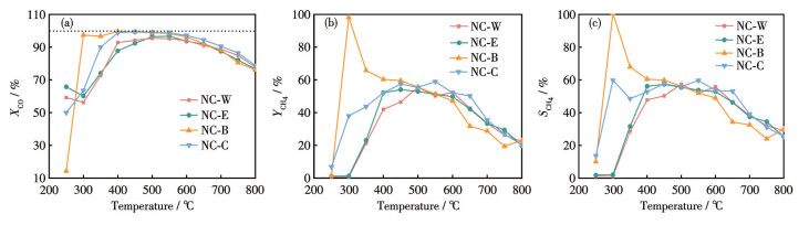
Catalytic activity tests for CO methanation were conducted at 0.6 MPa and a gas hourly space velocity (GHSV) of 10 000 mL·g-1·h-1. As shown in Fig.6, the preparation method significantly influenced catalyst activity. The impregnation-prepared catalysts NC-W and NC-E exhibited high CO conversion rate at 250 ℃ but demonstrated poor selectivity, attributed to their larger particle size. Nevertheless, NC-E showed superior activity to NC-W because the use of ethanol as a dispersant improved NiO dispersion compared to water, resulting in smaller particles and more exposed active sites. NC-B exhibited optimal low-temperature activity at 300 ℃, with CO conversion rate rapidly increasing from 14% to approximately 98%. It also demonstrates high CH4 yield and selectivity near 300 ℃. Analysis of its H2-TPR profile suggests that Ni species reduced at low temperatures are key to enhancing low-temperature activity. Literature reports also indicate that α-NiO reduced near 300 ℃ is the primary active component for low-temperature methanation[35]. However, as the temperature increased further, the activity of NC-B decreased significantly, likely due to weak Ni-support interactions leading to Ni sintering under high-temperature conditions. In contrast, NC-C exhibited superior activity above 500 ℃ compared to other catalysts. Combined with H2-TPR results, strong Ni-support interactions were evident in this catalyst. Furthermore, active sites can be replenished through the reduction of some framework NiO during the reaction. Consequently, the catalyst maintained good activity even under high-temperature conditions.
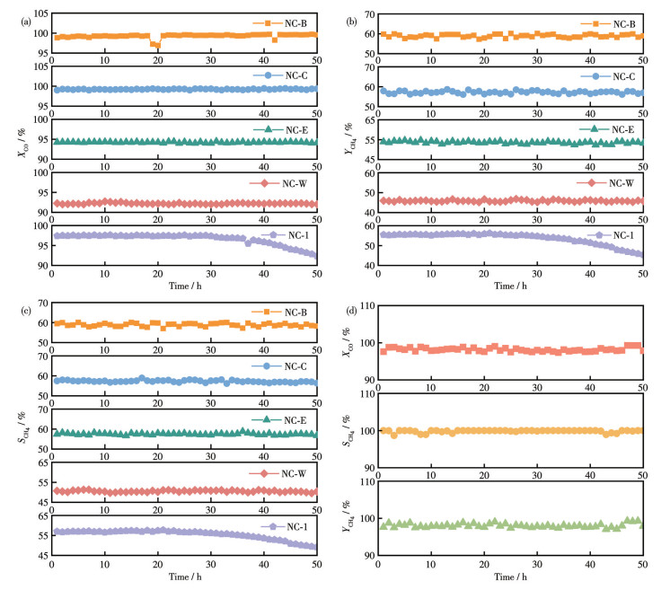
To investigate the stability of catalysts prepared by different methods and clarify the role of the mesoporous structure, a reference catalyst, NC-1, with lower mesoporosity (65.08%), was prepared. Stability tests were conducted at 450 ℃, 0.6 MPa, and a GHSV of 10 000 mL·g-1·h-1. As shown in Fig.7a-7c, NC-B, NC-C, NC-W, and NC-E maintained stable CO conversion rate over 50 h, demonstrating good activity and stability. NC-1 showed a significant decline in both CO conversion rate and CH4 selectivity after approximately 30 h. Based on characterization results, it can be concluded that the confinement effect of the CeO2 mesoporous structure enhances the anti-sintering capability of Ni, effectively maintaining catalyst stability.
Additionally, stability testing of NC-B was conducted at 300 ℃, 0.6 MPa, and a GHSV of 10 000 mL·g-1·h-1. Results in Fig.7d show that CO conversion rate remained around 98% with CH4 selectivity near 100% throughout the reaction, with no significant activity decline, indicating excellent stability under these conditions.
The XRD patterns of catalysts after 50 h of stability testing at 450 ℃ are shown in Fig.8a. Comparison with pre-reaction patterns reveals that after reaction, all catalysts exhibited faint diffraction peaks attributable to graphitic carbon. Among them, the spent NC-B catalyst showed the strongest carbon peak intensity, while support diffraction peaks were significantly weakened due to coking coverage. This indicates that catalysts prepared via the Ni sublimation method demonstrate relatively poor resistance to sintering and coking, attributed to weaker Ni-support interactions. In the spent NC-C and NC-E catalysts, almost no diffraction peaks for Ni or carbon deposits were detected. Based on previous analysis, these catalysts exhibited uniform Ni dispersion within the mesoporous structure or framework, with a significantly higher proportion of Ni exhibiting strong support interactions.
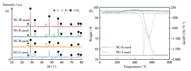
Analysis of the TG curve in Fig.8b reveals that the spent NC-E catalyst showed no weight loss across the temperature range, whereas the catalyst NC‑1 showed pronounced weight loss between 450-600 ℃. This indicates that the confinement effect of the mesoporous structure effectively suppresses sintering of active components and surface coking formation, thereby enhancing catalyst resistance.
To evaluate long-term anti-coking performance, TEM analysis was conducted on the four catalysts after 50 h of stability testing, with the results shown in Fig.9. The size and distribution of Ni particles in each catalyst showed no significant changes after reaction, indicating structural stability and excellent sintering resistance during operation. This is primarily attributed to the spatial confinement effect provided by the mesoporous CeO2 support, which effectively suppresses Ni migration and agglomeration at elevated temperatures, ensuring structural integrity during long-term operation.
In this work, a mesoporous CeO2 support with a confined structure was prepared via hydrothermal synthesis. The effects of three Ni loading methods—incipient wetness impregnation, coprecipitation, and bis (cyclopentadienyl)nickel sublimation—on CO methanation performance were systematically compared. Results indicate that all catalysts exhibit excellent sintering resistance due to the support′s confinement effect. However, their coking resistance, catalytic activity, and stability significantly depend on Ni dispersion and metal-support interaction strength.
Specifically, catalyst NC-B contained abundant weakly interacting NiO species. After reduction, it generated highly dispersed metallic Ni nanoparticles, providing more active sites. It exhibited optimal low-temperature activity, achieving ca. 98% CO conversion rate and ca. 100% CH4 selectivity at 300 ℃. Catalyst NC-E showed high activity and excellent coking resistance across a broad temperature range, owing to uniform Ni distribution within the pores and moderate support interaction. Catalyst NC-C maintained stable activity even at 550 ℃ because Ni is highly embedded into the CeO2 lattice, forming strong interactions. This study clarifies the intrinsic relationship between Ni loading method, Ni-based catalyst structure, and catalyst performance, laying a theoretical foundation for the rational design of high-performance Ni-based methanation catalysts.
程菁琳, 郭晓明, 孟涛, 胡旭, 李亮, 王彦哲, 黄文珠. 基于层状双氢氧化物前驱体的CO2甲烷化NiAlNd催化剂[J]. 无机化学学报, 2024, 40(8): 1592-1602CHENG J L, GUO X M, MENG T, HU X, LI L, WANG Y Z, HUANG W Z. NiAlNd catalysts for CO2 methanation derived from the layered double hydroxide precursor[J]. Chinese J. Inorg. Chem., 2024, 40(8): 1592-1602
CELORIA F, SALOMONE F, TAURO A, GANDIGLIO M, FERRERO D, CHAMPON I, GEFFRAYE G, PIRONE R, BENSAID S. Kinetic study and deactivation phenomena for the methanation of CO2 and CO mixed syngas on a Ni/Al2O3 catalyst[J]. Chem. Eng. J., 2025, 512: 162113 doi: 10.1016/j.cej.2025.162113
李柳柳, 张明伟, 汪颖军, 房克功. Fe/SAPO-34催化剂制备及其CO加氢制低碳烯烃性能研究[J]. 燃料化学学报(中英文), 2025, 53(4): 504-514LI L L, ZHANG M W, WANG Y J, FANG K G. Preparation of Fe/SAPO-34 catalyst and its catalytic performance for CO hydrogenation to light olefins[J]. Journal of Fuel Chemistry and Technology, 2025, 53(4): 504-514
HUSSAIN I, JALIL A A, HASSAN N S, FAROOQ M, MUJTABA M A, HAMID M Y S, SHARIF H M A, NABGAN W, AZIZ M A H, OWGI A. Contemporary thrust and emerging prospects of catalytic systems for substitute natural gas production by CO methanation[J]. Fuel, 2022, 311: 122604 doi: 10.1016/j.fuel.2021.122604
ZHANG J, JIA X Y, LIU C J. Structural effect of Ni/TiO2 on CO methanation: Improved activity and enhanced stability[J]. RSC Adv., 2022, 12(2): 721-727 doi: 10.1039/D1RA08021K
LI J X, LIANG Y F, LI Z, FAN K, WANG C X, LI K, LI Y, SUN X, NING P, WANG F. Synergistic effect of Ni and NiO in hydrogen reduction for CO methanation[J]. Sep. Purif. Technol., 2024, 335: 126178 doi: 10.1016/j.seppur.2023.126178
HOU Z G, CHEN Y M, MA X, ZHOU L, WANG W, QIU J S, ZHANG Y. Cerium-promoted Ni/SiO2 catalyst for CO methanation[J]. Can. J. Chem. Eng., 2023, 101(12): 7068-7077 doi: 10.1002/cjce.24955
王宏伟, 吴俊霞, 王晓燕, 王红, 刘进荣. La-Ni/Al2O3-ZrO2催化剂中钙钛矿型LaNiO3的形成及其CO甲烷化性能[J]. 燃料化学学报(中英文), 2021, 49(2): 186-197WANG H W, WU J X, WANG X Y, WANG H, LIU J R. Formation of perovskite-type LaNiO3 on La-Ni/Al2O3-ZrO2 catalysts and their performance for CO methanation[J]. Journal of Fuel Chemistry and Technology, 2021, 49(2): 186-197
夏勇辉, 沈卫华, 王杰, 方云进. Ni/W-Al2O3催化剂在富氢气体中CO选择性甲烷化的研究[J]. 现代化工, 2023, 43(6): 150-154XIA Y H, SHEN W H, WANG J, FANG Y J. Study on selective CO methanation over Ni/W‑Al2O3 catalyst in hydrogen‑rich gas[J]. Modern Chemical Industry, 2023, 43(6): 150-154
LI Y T, SHEN C Y, JIANG C Y, LIANG C J, CHEN B W, DING W P, GUO X F. Surrounded Ni@Al2O3 as a robust catalyst for CO methanation: The size effect of Ni nanoparticles[J]. ACS Catal., 2025, 15: 9728-9737 doi: 10.1021/acscatal.5c01212
HOU Z G, CHEN Y M, WANG C, MA X, YANG H, WANG W, ZHANG Y. The promotional effects of Mn on Ni/SiO2 catalysts for CO methanation[J]. React. Kinet. Mech. Catal., 2023, 136(2): 587-601 doi: 10.1007/s11144-023-02377-0
李新立, 张笑楠, 杜臻臻, 韩飞雪, 范志辉, 张少康, 张振洲, 涂维峰, 韩一帆. Ni-CeO2界面富电子Ni原子变化规律及其促进CO甲烷化的作用机制研究[J]. 催化学报, 2025, 74(7): 177-190LI X L, ZHANG X N, DU Z Z, HAN F X, FAN Z H, ZHANG S K, ZHANG Z Z, TU W F, HAN Y F. Study on the variation law of electron-rich Ni atoms at the Ni-CeO2 interface and its mechanism for promoting CO methanation[J]. Chin. J. Catal., 2025, 74(7): 177-190
REN J, LEI H, MEBRAHTU C C, ZENG F, ZHENG X S, PEI G, ZHANG W H, WANG Z D. Ni-based hydrotalcite-derived catalysts for enhanced CO2 methanation: Thermal tuning of the metal-support interaction[J]. Appl. Catal. B‒Environ., 2024, 340: 123245 doi: 10.1016/j.apcatb.2023.123245
TAPIA J, OSTOS C, MENDOZA C, ARBOLEDA J, ECHAVARRIA A. Effect of the Ni/CeO2 mesoporous structure on the proper balance of active sites present for CO2 methanation: An in-situ NAP-XPS study[J]. Environ. Technol. Innov., 2024, 35: 103713 doi: 10.1016/j.eti.2024.103713
HAN Y H, ZHAO J X, QUAN Y H, YIN S N, WU S P, REN J. Highly efficient LaxCe1-xO2-x/2 nanorod-supported nickel catalysts for CO methanation: Effect of La addition[J]. Energy Fuels, 2021, 35(4): 3307-3314 doi: 10.1021/acs.energyfuels.0c04008
LI F, SU W T, FANG Y Y, YAO K, SUN Y, DAI C Y, ZHAO B R. Enhancement in the activity and selectivity of Co/CeO2 for CO2 methanation by the design of Co-O-Ce structure[J]. Chem. Eng. J., 2025: 166365
LI J W, DU C C, FENG Q Y, ZHAO Y R, LIU S X, XU J L, HU M, ZENG Z Z, ZHANG Z, SHEN H X, ZHANG Y X, ZHU J Q, ZHANG L J, ZHAO W, HUANG J Y, XIONG H F. Evolution and performances of Ni single atoms trapped by mesoporous ceria in dry reforming of methane[J]. Appl. Catal. B‒Environ., 2024, 354: 124069 doi: 10.1016/j.apcatb.2024.124069
ATZORI L, ROMBI E, MELONI D, MONACI R, SINI M F, CUTRUFELLO M G. Nanostructured Ni/CeO2-ZrO2 catalysts for CO2 conversion into synthetic natural gas[J]. J. Nanosci. Nanotechnol., 2019, 19(6): 3269-3276 doi: 10.1166/jnn.2019.16612
EVTUSHKOVA A, HEINRICHS J M J J, KOSINOV N, HENSEN E J M. CO2 methanation of Co/CeO2 prepared by wetness impregnation of Co on flame-synthesized CeO2[J]. ChemCatChem, 2025, 17(17): e00679 doi: 10.1002/cctc.202500679
OSTI A, COSTA S, RIZZATO L, SENONER B, GLISENTI A. Photothermal activation of methane dry reforming on perovskite-supported Ni-catalysts: Impact of support composition and Ni loading method[J]. Catal. Today, 2025, 449: 115200 doi: 10.1016/j.cattod.2025.115200
NIU Y X, ZHENG X R, GUO B H, LIU H Y, JIN Y, NIU J T. Particle size tuning of Ni/CeO2 catalysts and their performance in methane dry reforming reaction[J]. Gas Sci. Eng., 2025: 205790
CHEN C C, WANG W B, REN Q H, YE R P, NIE N, LIU Z, ZHANG L L, XIA J B. Impact of preparation method on nickel speciation and methane dry reforming performance of Ni/SiO2 catalysts[J]. Front. Chem., 2022, 10: 993691 doi: 10.3389/fchem.2022.993691
KUMAR S, JAIN A, MIYAOKA H, ICHIKAWA T, KOJIMA Y. Catalytic effect of bis (cyclopentadienyl) nickel Ⅱ on the improvement of the hydrogenation-dehydrogenation of Mg-MgH2 system[J]. Int. J. Hydrog. Energy, 2017, 42(27): 17178-17183 doi: 10.1016/j.ijhydene.2017.05.090
JIANG H P, LI X, CHEN S T, WANG H Q, HUO P W. g-C3N4 quantum dots-modified mesoporous CeO2 composite photocatalyst for enhanced CO2 photoreduction[J]. J. Mater. Sci. ‒Mater. Electron., 2020, 31(22): 20495-20512 doi: 10.1007/s10854-020-04568-0
SHEN Y T, GAO Y K, YANG H, LU Z Y, LI M M, WU C E, WANG S, XU L L, GAO F, CHEN M D. Mesoporous CeO2 hollow-nanosphere-supported Ni catalysts for enhanced low-temperature CO2 methanation[J]. J. Environ. Chem. Eng., 2026, 14(2): 121136 doi: 10.1016/j.jece.2026.121136
MARCONI E, TUTI S, LUISETTO I. Structure-sensitivity of CO2 methanation over nanostructured Ni supported on CeO2 nanorods[J]. Catalysts, 2019, 9(4): 375 doi: 10.3390/catal9040375
LIN S X, LI Z H, LI M S. Tailoring metal-support interactions via tuning CeO2 particle size for enhancing CO2 methanation activity over Ni/CeO2 catalysts[J]. Fuel, 2023, 333: 126369 doi: 10.1016/j.fuel.2022.126369
WANG T T, TANG R, LI Z H. Enhanced CO2 methanation activity over Ni/CeO2 catalyst by adjusting metal-support interactions[J]. Mol. Catal., 2024, 558: 114034
LIAO L, CHEN L D, YE R P, TANG X L, LIU J. Robust nickel silicate catalysts with high Ni loading for CO2 methanation[J]. Chem. Asian J., 2021, 16(6): 678-689
LIN S X, KANG L, GONG L C, TAO L G, XI S B, LI Z H, LIU W. Facet specificity of yttrium doping on CO2 methanation over Ni/CeO2 catalysts[J]. Chem. Eng. J., 2024, 502: 157840 doi: 10.1016/j.cej.2024.157840
LI Y D, YANG Y H, HUANG Z Z, ZHOU H L, ZENG R Y, LIN X H, MA X L, WANG S C, XIANG S C, ZHANG Z J. Oxygen-vacancy-rich Ni/CeO2: UiO-66-derived high-efficiency catalyst for low-temperature CO2 methanation[J]. Chem. Eng. J., 2025, 511: 162073
ELHAMDY W A, SAID A E A A, GODA M N, KHALIL K M S. Promotional effect of CeO2 and Fe2O3 species on mesoporous silica as efficient catalysts for the vapor-phase dehydration of iso-butyl alcohol to isobutylene[J]. Appl. Catal. A‒Gen., 2025, 702: 120352 doi: 10.1016/j.apcata.2025.120352
BUENO J, LOPEZ S, MARTINEZ I, MARTIN I, GUILLEN E, DIESTE V P, DAVO A, LOZANO D, BUENO A. Highly active, selective and stable Ru/NiO-CeO2 catalyst for low-temperature CO2 methanation[J]. Chem. Eng. J., 2025: 167951
FENG W W, HOU Y, YAN J, LI G B, ZHANG H X, HUANG S, HUANG T, LIU W M, ZHANG S L, PENG H G. Preparation of highly dispersed Pt catalyst by CeOx ‘islands’ modification of dendritic mesoporous SiO2: CO as a probe molecule[J]. Catal. Today, 2024, 437: 114721
TANG R, ULLAH N, HUI Y J, LI X, LI Z H. Enhanced CO2 methanation activity over Ni/CeO2 catalyst by one-pot method[J]. Mol. Catal., 2021, 508: 111602

Figure 2 (a) N2 adsorption-desorption isotherms and (b) pore size distribution curves of the samples

Figure 3 (a) H2-TPR curves of the catalysts; (b) Survey, (c) Ce3d, and (d) Ni2p XPS spectra of the catalysts

Figure 5 (a, b) TEM images, (c) HRTEM images, and (d) EDX spectra of catalysts: (a1-d1) NC-W, (a2-d2) NC-E, (a3-d3) NC-B, and (a4-d4) NC-C
Inset: elemental contents.

Figure 6 Catalytic activities of catalysts: (a) CO conversion rates, (b) CH4 yields, and (c) CH4 selectivities

Figure 7 Stability test of the catalysts: (a) CO conversion rates, (b) CH4 yields, and (c) CH4 selectivities; (d) Stability test of NC-B

Figure 8 (a) XRD patterns of spent catalysts; (b) TG curves (solid line) and DTG curves (dashed line) of the used NC-E and NC-1

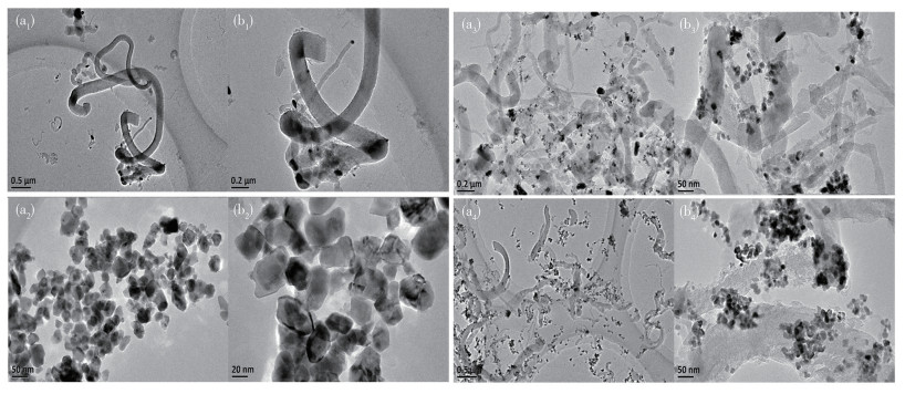
Figure 9 (a) TEM and (b) HRTEM images of the spent catalysts: (a1, b1) NC-W, (a2, b2) NC-E, (a3, b3) NC-B, and (a4, b4) NC-C
Table 1. Physicochemical properties of catalysts prepared by different loading methods
| Catalyst | Crystallite size of CeO2/nm | Mesoporous content/% | SBETa/(m2·g-1) | |
| CeO2⁃0 | 7.0 | 62.78 | 147 | — |
| NC⁃C | 9.0 | 92.4 | 104 | 34.61 |
| NC⁃B | 12.0 | 95.04 | 107 | 37.22 |
| NC⁃E | 28.3 | 86.84 | 91 | 28.33 |
| NC⁃W | 35.4 | 93.46 | 91 | 28.02 |
| NC⁃1 | — | 65.08 | 9 | — |
 下载: 导出CSV

 扫一扫看文章

扫一扫关注我们