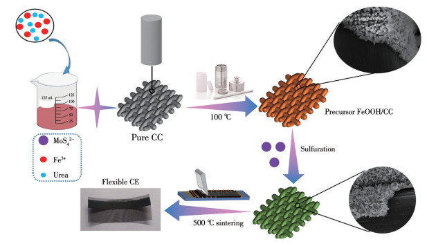
Scheme 1.
Fabrication process of the DSSC CE with the FMS/CC composite
FeMoS4/carbon fiber cloth composites: Preparation and application in dye-sensitized solar cells
Qian ZHANG , Yuxuan ZHANG , Yongguang YANG , Ruijie BAI , Yuandong LI , Ling LI

As global energy demand continues to grow annually, the advancement of renewable energy becomesincreasingly vital[1-3]. Among all renewable energy technologies, photovoltaic technology stands out as the most promising[4-9]. The third-generation dye-sensitized solar cells (DSSCs) are widely employed due to their cost-effectiveness, straightforward fabrication, stable performance, and high PCE[10-14]. Typical DSSCs feature a sandwich structure, consisting primarily of a counter electrode (CE), a sensitizing dye, a photoanode, and an electrolyte[8, 15-17]. Pt, owing to its superior conductivity and catalytic activity in triiodide reduction, remains the most frequently used CE material in traditional iodine electrolytes for DSSCs[18-21]. However, Pt cannot be widely used due to its material scarcity and high price[22-23]. Therefore, identifying CE materials with superior electrochemical stability and enhanced economic efficiency to replace Pt is essential for the rapid advancement of DSSCs.
Transition metal sulfides (TMSs) are widely used because of their excellent physical and chemical properties. Their amorphous state has more defects and active sites, and their nanomaterials have characteristics of short-range order and long-range disorder, which can be used to prepare battery electrode materials and catalysts related to the chemical industry. The inherent disordered structure of amorphous materials will enhance their activity, resulting in the increase of active sites and the improvement of the intrinsic activity of these sites, showing better activity than crystal nanomaterials in fields such as hydroelectrolysis. Due to its excellent catalytic performance, it is widely used in hydrogen evolution, water decomposition, and supercapacitors[24-25]. The amorphous phase increases the catalytic activity of electrolyte regeneration due to lattice distortion and more marginal overhanging bonds. Yu et al. prepared an amorphous nitrogen-doped carbon MoS3 nanobattery with a hollow porous structure, which could achieve high capacity and improve battery life for Li-S batteries[26]. Jiang et al. used a gas/liquid/solid interface self-assembly method to prepare ordered two-dimensional amorphous Co-S nanoarrays on clean F-doped tin oxide conductive glass (FTO) glass, and the PCE of DSSCs composed of this CE was 7.78%, about 20% higher than that of a traditional Pt CE (6.51%)[27].
Transition metal Ni has good catalytic activity, so its introduction can effectively enhance catalytic activity. For example, Jiang′s group directly generated amorphous Ni-CO-S films in FTO by electrodeposition technology, and used them as DSSC CEs with a PCE of 8.18%, which was much higher than the rare metal Pt CE[28]. Similarly, the Fe element also has a similar activity to Ni. The catalytic capacity of hydrogen evolution when ternary transition metal sulfide was used as a catalyst, was comparable to that of Pt. Amorphous FeMoS4 has stronger activity when used for electrocatalytic hydrogen evolution[29-30]. Therefore, introducing FeMoS4 into DSSCs as a CE catalytic material may increase PCE. However, as TMSs also have similar defects, the conductivity is not good, so an appropriate substrate should be selected. Carbon fiber cloth (CC) is composed of carbon fiber with a diameter of 5-10 μm, which has excellent electrical conductivity. To further modify the surface of CC, nanostructures can be grown on the surface of CC to increase the active sites required for electrochemical reaction. FeMoS4 is widely used in various catalytic fields such as electrocatalytic hydrogen evolution, wastewater treatment, supercapacitors (symmetric and asymmetric), and lithium batteries, and is an excellent carrier for composite materials[31].
Therefore, the combination of CC and TMSs can better coordinate the advantages of both. Herein, a simple two-step hydrothermal method was adopted to synthesize an amorphous FeMoS4/CC (FMS/CC) composite. A series of characterizations confirmed the successful preparation of amorphous FMS/CC. The amorphous substances can supply more active sites and accelerate the decrease of I3-. Moreover, by scraping and coating on a flexible titanium mesh, which possesses lower sheet resistance, the resulting DSSCs exhibited a lower series resistance (Rs) compared to those fabricated on conventional FTO conductive substrates under identical conditions. At the same time, electrochemical methods such as cyclic voltammetry (CV) and electrochemical impedance spectroscopy (EIS) showed that the PCE of DSSCs using FMS/CC as CE was about 9.51%, which was higher than that of the Pt CE (about 8.15%), indicating that the use of amorphous transition metal sulfide instead of non-platinum materials has great potential.
Chemical reagents such as FeCl3·6H2O, urea, (NH4)2MoS4, polyacrylonitrile (PAN), nano TiO2 (P25), N, N-dimethylformamide (DMF) were purchased from McLean Reagent Co., Ltd., and directly used without any treatment. FTO (15 Ω·cm2) was purchased from NSG Company in Japan.
In a typical synthesis, the FeOOH/CC precursor was first prepared. FeCl3·6H2O (8.5 mmol) and urea (20 mmol) were dissolved in 35 mL of deionized water and stirred for 30 min to form a transparent, light orange solution. Before use, the CC was soaked in hydrochloric acid for 30 min and then rinsed three times with deionized water. A piece of clean CC (0.2 g) was then added, and the mixture was sealed in a 50 mLautoclave and heated at 100 ℃ for 4.5 h. After cooling to room temperature, the product was washed repeatedly and dried at 55 ℃ to obtain the FeOOH/CC precursor. Subsequently, the precursor was vulcanized to synthesize the final product. The as-prepared FeOOH/CC was immersed in a solution containing (NH4)2MoS4 (0.15 mmol) dissolved in 30 mL of deionized water. This mixture was subjected to a second hydrothermal treatment in an autoclave at 160 ℃ for 11 h. Finally, after cooling to ambient temperature, the resulting sample was collected, washed thoroughly, and dried, yielding the lamellar FMS/CC composite. For comparison, a control sample of pure FMS powder was synthesized following the identical procedure, except that CC was omitted from the hydrothermal solution; all subsequent steps, including annealing, remained the same.
0.15 g of FMS/CC was cut into pieces and ground into powder in the mortar. After undergoing two rounds of hydrothermal treatment, the CC exhibited a certain degree of brittleness. Subsequently, it was cut into pieces and subjected to high-energy ball milling, enabling it to be ground into powder and achieve uniformity. Then, the scraping paste (A paste was formulated by blending ethyl cellulose, terpineol, and ethanol with a mass ratio of 1:4:10) was added, and continued grinding. After about 20 min, when the material in the mortar became a paste, it was scraped onto the clean titanium mesh fixed on the scraping table with a special scraper blade. The scraping area was 0.7 cm×5 cm, and the scraping process strength was uniform to avoid uneven CE film thickness. The scraped CE was dried at 90 ℃ for 4 h, then placed in a tube furnace filled with nitrogen and heated at 500 ℃ for 4 h, and the CE was obtained after the temperature dropped. During the experiment, control variables were used: only the film thickness of the CE was changed, and other conditions remained unchanged. The preparation method of the CEs with different film thicknesses was the same as above, and the film thickness of the CE was changed by changing the number of transparent tape layers. For convenience of recording, the CEs with thicknesses of 9, 11, 13, 15, and 17 µm were abbreviated as FMS/CC-x, where x was 1, 2, 3, 4, and 5, respectively.
The TiO2 photoanode was prepared on a clean 0.36 cm2 FTO via silkscreen five times to control the film thickness at about 15 μm. Thereafter, the TiO2 photoanode was stabilized at 500 ℃ for 30 min under an air atmosphere. To further use, the TiO2 photoanode was immersed in N719 dye solution for 24 h to obtain the dye-sensitized TiO2 photoanode. The electrolyte was prepared by dissolving lithium iodide (LiI, 0.06 mol·L-1), iodine (I2, 0.03 mol·L-1), 4-tert-butylpyridine (TBP, 0.5 mol·L-1), 1-propyl-3-methylimidazolium iodide (PMII, 0.6 mol·L-1), and guanidinium thiocyanate (GSCN, 0.1 mol·L-1) in acetonitrile. The resulting solution was then magnetically stirred for 30 min toensure homogeneity. At last, the prepared titanium mesh was pasted on the glass and assembled with the TiO2 photoanode, sealed with a thin film.
Many factors affect the electrocatalytic activity of DSSCs on CEs. To explore the effect of film thickness on the electrocatalytic performance of CEs, five sets of FMS/CC CEs with different film thicknesses and a comparison experiment with Pt CEs were designed, and a series of electrochemical characterizations were conducted on them.
The surface morphology and lattice structure of FMS/CC were investigated by field emission scanning electron microscopy (SEM, FEI, NOVA NanoSEM 450) and transmission electron microscopy (TEM, 200 kV, JEOL, JEM-2100 Plus). The phase structure of the sample was analyzed by X-ray diffraction (XRD, D8-Advance, Bruker AXS, Cu Kα radiation, λ=0.154 06 nm, 40 kV, 40 A, 2θ=15°-65°). X-ray photoelectron spectroscopy (XPS, Thermo VG, ESCALAB250) was employed to determine the elemental composition and chemical states of the materials. Electrochemical measurements were performed on an electrochemical workstation (CHI 660E). The catalytic ability of the material was evaluated by Tafel plot measurements, which were recorded using a symmetrical two-electrode cell at a scan rate of 20 mV·s-1 from -0.7 to 0.7 V. CV curves were recorded in a three-electrode system at a scan rate of 10 mV·s-1. EIS was conducted in the frequency range of 0.1 Hz to 100 kHz to measure the parameters of the DSSCs. The photocurrent density-voltage (J-V) characteristics were measured under AM 1.5G simulated sunlight (100 mW·cm-2) using a solar simulator (91160, Oriel, Newport, USA).
SEM can be used to observe the microscopic morphology of the composite, while TEM can further characterize the structure of the morphology. Fig.1a shows the CC before hydrothermal growth. The surface was very smooth, and the arrangement was relatively regular. Fig.1b-1e showed that FMS was successfully and evenly attached to the surface of CC after hydrothermal reaction. The diameter of CC was 9.454 μm, and the diameter of a single root FMS/CC reached 13.64 μm after hydrothermal growth. At the same time, the columnar structure with an irregular tip and rough surface can be seen by magnification. Compared with pure CC, FMS/CC possessed a larger specific surface area and an increased number of active sites. As shown in Fig.1f, the FMS synthesized without a CC substrateexhibited severe agglomeration, which is detrimental to its catalytic performance as a CE. During TEM sample preparation, FMS was stripped off from the CC using ultrasound. It can be seen from Fig.1g-1i that the surface of the morphology was rough, the tip was irregular, and there was no diffraction lattice, indicating that FMS had an amorphous structure. Fig.1j-1m indicated that the tested FMS contained Fe, Mo, and S elements.
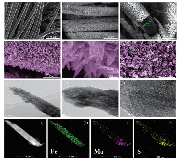
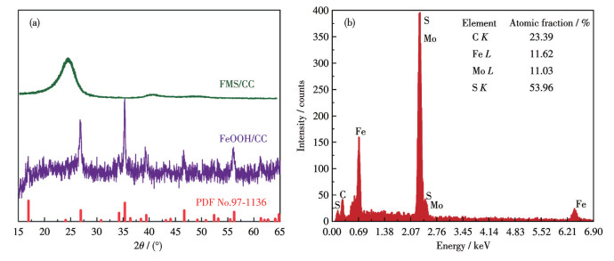
Fig.2a shows the XRD patterns of FMS/CC and FeOOH/CC. The diffraction peaks of 16.5°, 26.5°, 35.6°, 39.3°, 46.1°, 52.3°, 55.8°, and 64.9° of the precursor FeOOH/CC are correlated with FeOOH (PDF No.97-1136), corresponding to crystal planes of (200), (130), (211), (301), (411), (600), (251), and (541), respectively[32], and the diffraction peak at 26.5° corresponds to the (002) plane of graphitic carbon[33]. There were no other peaks in the XRD pattern of FMS/CC after vulcanization except the characteristic peak of CC and two rather wide "rise peaks" (diffuse reflection peaks), which is a typical feature of solid amorphous[34-35], indicating that the precursor FeOOH/CC became amorphous after being vulcanized by(NH4)2MoS4, corresponding to the TEM characterization above. Fig.2b is the energy dispersive X-ray spectrum (EDS) of FMS/CC, which can directly obtain the types and relative contents of elements on the surface of the sample. FMS/CC only contained four elements (S, C, Mo, and Fe). In addition, the atomic ratio of Fe, Mo, and S elements was approximately 1:1:4, which is consistent with the stoichiometric ratio of FeMoS4, while the C element was from CC.
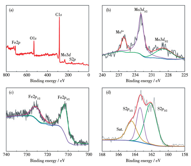
To further verify the synthesis of FMS/CC and the valence states of the contained elements[36], XPS was used. Fig.3a indicated that there were only C, O, S, Mo, and Fe. Fig.3b shows the Mo3d spectrum, the peaks correspond to the Mo3d5/2 at 229.3 eV and the Mo3d3/2 at 233.0 eV. The peak at 236.2 eV proves the presence of Mo6+ in the sample[37]. The Fe2p spectrum (Fig.3c) had two main peaks of Fe2+2p3/2 and Fe2+2p1/2 appeared at the binding energies of 711.8 and 725.9 eV[38]. The S2p spectrum (Fig.3d) reveals the S2-, characterized by the S2p3/2 and S2p1/2 spin-orbit doublet at 162.1 and 163.3 eV, respectively, along with a satellite peak (Sat.) at 164.5 eV[39]. The XPS analysis and the above characterization can fully indicate the successful synthesis of FMS/CC with an amorphous structure.
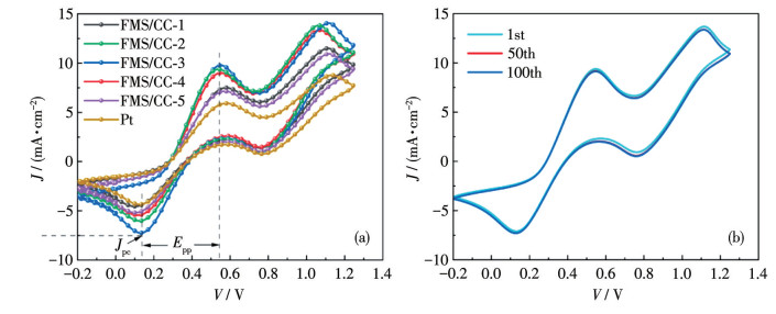
Fig.4a and 4b display the CV curves of a three-electrode test system to characterize the electrocatalytic activity of FMS/CC on CEs with different film thicknesses[40]. In Fig.4a, the two pairs of redox peaks can be identified regardless of film thickness, indicating analogous catalytic activity with Pt materials. The cathode peak current density (Jpc) reflects the catalytic performance of the material for I3-. |Jpc| from large to small was FMS/CC-3 > FMS/CC-2 > FMS/CC-4 > FMS/CC-5 > FMS/CC-1 > Pt, where the maximum |Jpc| value of FMS/CC-3 was about 7.5 mA·cm-2, and all of FMS/CC-x were larger than the Pt CE. This indicates that FMS/ CC-3 is more conducive to the reduction reaction of I3- and has better electrocatalytic activity. The peak-to-peak potential separation (Epp), a measure of electrocatalytic kinetics, was found to be inversely correlated with the |Jpc|. The FMS/CC-3 CE demonstrated the smallest Epp, signifying the most facile kinetics and the highest catalytic activity for the I3-/I- redox reaction, which is essential for efficient triiodide reduction at the CE. Fig.4b shows the CV curves of FMS/CC-x tested continuously for 100 cycles. It can be seen that the CV curve remained unchanged, and there were two pairs of obvious redox peaks, indicating that FMS/CC not only had good reversibility when used as a DSSC CE, but also was very stable in the electrolyte containing I3-/I-. It is not easy to be corroded and dissolved, which fully indicates that the electrocatalytic activity of FMS/CC-3 was the highest and stable when the film thickness of the CE was 13 μm.
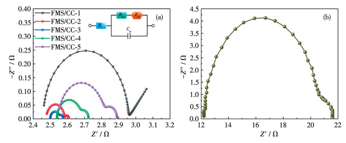
Three important parameters, namely interface charge transfer resistance (Rct), Rs, and I3-/I- electron pair diffusion impedance (ZN) in the electrolyte, can be obtained by EIS (Fig.5a). The inset in Fig.5a presents the equivalent circuit used for fitting, with Cμ representing the interfacial double-layer chemical capacitance. Table 1 lists the specific values. The higher Rs of the Pt CE is attributed to its use of a high-resistance FTO substrate, in contrast to the FMS/CC-x CEs, which is fabricated on a more conductive titanium mesh. In addition, since the thickness of the CE will also affect Rs, the Rs was sorted from large to small as follows: Pt > FMS/CC-5 > FMS/CC-4 > FMS/CC-3 > FMS/CC-2 > FMS/CC-1 based on Fig.5a. Generally, the radius of the first-class semicircle represents the Rct value, and the smaller the radius, the smaller the Rct value, indicating that the CE material had excellent catalytic performance in reducing I3-. It can be seen from the figure that the order of Rct from small to large was FMS/CC-3 < FMS/ CC-2 < FMS/CC-4 < FMS/CC-5 < FMS/CC-1 < Pt, indicating that FMS/CC-3 was more conducive to the reduction of I3- on the CE. If the film thickness is too thin, the reduction of I3- cannot be more effective, so the Rct will be larger. With the increase of the thickness of the CE film, although the active material increases, it will also increase Rs, and cause the CE surface to crack. The harm brought by this situation is far greater than the benefit brought by the increase of active substances, which is not conducive to the transfer of charge. The ZN is approximately equal to the radius of the second-class semicircle, and the smaller ZN indicates that I3-/I- diffuses more rapidly in the electrolyte, resulting in a larger diffusion coefficient. The film thickness of FMS/CC-3 is more conducive to the diffusion of iodine ions, and too thick or too thin film thickness will reduce ZN. According to EIS analysis, when the film thickness of FMS/CC was 13 μm, it had the smallest Rct and ZN, and the largest electrocatalytic activity, as verified by the verification results of CV.
Inset: corresponding equivalent circuit diagram.
 下载:
导出CSV
下载:
导出CSV
| CE | Rs / (Ω·cm2) | Rct / (Ω·cm2) | ZN / (Ω·cm2) |
| FMS/CC-1 | 2.46 | 0.25 | 0.11 |
| FMS/CC-2 | 2.48 | 0.05 | 0.02 |
| FMS/CC-3 | 2.50 | 0.03 | 0.01 |
| FMS/CC-4 | 2.54 | 0.07 | 0.03 |
| FMS/CC-5 | 2.55 | 0.13 | 0.05 |
| Pt | 12.17 | 4.25 | 0.45 |
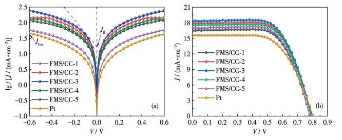
The Tafel polarization test is also a method for evaluating the electrochemical performance of CE materials, which can obtain the limiting diffusion current density (Jlim) and exchange current density (J0). Fig.6a shows the Tafel plots of FMS/CC-x. It can be seen that the Jlim of FMS/CC-3 was the largest, about 2.40 mA·cm-2, and the minimum of the Pt CE was about 1.74 mA·cm-2, and that of the other CEs was larger than that of the Pt CE. This indicates that using titanium mesh as a conductive carrier is beneficial for the diffusion of iodine electrons in the electrolyte, suggesting that the more porous the titanium mesh, the higher the diffusion coefficient, which is due to its porous structure. But if the CE film is too thick, it will cause surface cracking, indirectly hindering the transmission of iodine ions, and thus reducing Jlim. Another important parameter, J0, is inversely proportional to Rct in EIS. The larger the J0, the stronger the iodine reduction catalytic performance of the CE. The intersection point between the slope of the cathode branch (polarization region) and the equilibrium potential was denoted as J0 and the J0 from large to small was FMS/CC-3 > FMS/CC-2 > FMS/CC-4 > FMS/CC-5 > FMS/CC-1 > Pt, so FMS/CC-3 had a largest Jlim and J0, indicating that FMS/CC-3 had the best catalytic activity. This is consistent with the above conclusions of CV and EIS.
The photoelectric performance of the CEs with different film thicknesses were tested[29], and the results are displayed in Fig.6b. It can be seen that there was little difference in open-circuit voltage (Voc), which is because the light anode used in the test was the same batch, so the Voc value was within a certain range; the short-circuit current density (Jsc) in descending order was FMS/CC-3 > FMS/CC-2 > FMS/CC-4 > FMS/CC-5 > FMS/CC-1 > Pt. The Jsc values of the other CEs, except FMS/CC-1, were greater than Pt. This is attributed to the growth of FMS/CC, which provides a larger specific surface area and a greater number of active sites, thereby resulting in superior catalytic activity compared to the Pt CE. As can be seen from the table, the maximum Jsc of the FMS/CC-3 CE was about 18.31 mA·cm-2. When the film thickness is too thin, the CE will be unable to catalyze the reoxidation reaction better due to the lack of catalytic materials, so the Jsc will be reduced. When the film thickness is too thick, although the required active material is increased, the distance between the CE and the electrolyte increases, but the Rct becomes larger, and the surface and interior of the CE film are prone to cracking, and even lead to falling off, which will greatly increase the Rs value, and ultimately make the Jsc smaller. The porous titanium mesh with lower self-resistance was used as the conductive carrier for the FMS/CC-x CEs. Therefore, combined with the above analysis, the smaller the Rct and Rs of the CE, the larger the fill factor (FF) of the CE, as shown in Table 2. Finally, through the comparison of the above groups of experiments, when the film thickness was 13 μm, the Voc of FMS/CC-3 was about 0.79 V, the Jsc was about 18.31 mA·cm-2, the FF was about 0.65, and the PCE was about 9.51%.
下载:
导出CSV
| CE | Voc / V | Jsc / (mA·cm-2) | FF | PCE / % |
| FMS/CC-1 | 0.782±0.008 | 16.54±0.03 | 0.66±0.02 | 8.56±0.05 |
| FMS/CC-2 | 0.796±0.002 | 17.90±0.02 | 0.65±0.02 | 9.28±0.04 |
| FMS/CC-3 | 0.796±0.002 | 18.31±0.02 | 0.65±0.02 | 9.51±0.02 |
| FMS/CC-4 | 0.792±0.002 | 17.56±0.02 | 0.66±0.03 | 9.14±0.03 |
| FMS/CC-5 | 0.782±0.008 | 16.99±0.03 | 0.66±0.02 | 8.79±0.01 |
| Pt | 0.796±0.004 | 15.58±0.02 | 0.61±0.03 | 7.81±0.03 |
In this work, amorphous FMS/CC composites were successfully synthesized on CC via a two-step hydrothermal method. The composite synergistically combines the high electrical conductivity of the CC scaffold with the efficient catalytic performance of FMS, effectively overcoming the inherent limitations of the individual components, namely the lack of active sites in pure CC and the severe agglomeration of pure FMS. SEM and TEM analyses reveal that the FeMoS4 material forms a uniform, vertically aligned columnar structure on the CC. This morphology provides a significantly larger specific surface area and a greater number ofactive sites compared to pure CC. Furthermore, this study demonstrates that the film thickness is a critical parameter for photovoltaic performance. Through systematic optimization, the FMS/CC-3 CE with a film thickness of 13 μm exhibited the highest electrocatalytic activity, enabling the corresponding DSSCs to achieve a PCE of about 9.51%.
ASOK A, HARIBABU K. Synthesis and performance of polythiophene-iridium oxide composite as counter electrode in dye sensitized solar cell[J]. Curr. Appl. Phys., 2023, 49: 64-69 doi: 10.1016/j.cap.2023.02.019
NOROUZIBAZAZ M, GHOLIVAND M B, TAHERPOUR A A, MIRZAEI M. Experimental and computational investigation of multi-walled carbon nanotubes decorated by Co-Ni-Se@MoSe2 core-shell as a sustainable counter electrode for dye-sensitized solar cells[J]. Mater. Today Energy, 2023, 38: 101447 doi: 10.1016/j.mtener.2023.101447
TOMAR N, DHAKA V S, SUROLIA P K. A brief review on carbon nanomaterial counter electrodes for N719 based dye-sensitized solar cells[J]. Mater. Today: Proceed., 2021, 43: 2975-2978 doi: 10.1016/j.matpr.2021.01.325
SHARMA K, SHARMA V, SHARMA S. Dye-sensitized solar cells: Fundamentals and current status[J]. Nanoscale Res. Lett., 2018, 13: 1-46 doi: 10.1186/s11671-017-2411-3
ABDULLAEV S S, BREESAM Y F, ALZUBAIDI A A, TRIPATHI A K, KAREEM A, KUZNETSOV S V, ALAWSI T, ZABIBAH R S. ZnO@ZnCo2O4 core-shell: A novel high electrocatalytic nanostructure to replace platinum as the counter electrode in dye-sensitized solar cells[J]. Mater. Sci. Semicond. Process, 2023, 165: 107709 doi: 10.1016/j.mssp.2023.107709
QI X N, SONG C P, ZHANG W H, SHI Y Q, GAO Y Y, LIU H, CHEN R, SHANG L W, TAN H R, TAN F R. Bidirectional targeted therapy enables efficient, stable, and eco-friendly perovskite solar cells[J]. Adv. Funct. Mater., 2023, 33(19): 2214714 doi: 10.1002/adfm.202214714
ZH M, YE M D, WANG W L, MA C Y, WANG S, LIU Q L, LIAN T Q, HUANG J S, LIN Z Q. Synergistic cascade carrier extraction via dual interfacial positioning of ambipolar black phosphorene for high-efficiency perovskite solar cells[J]. Adv. Mater., 2020, 32(28): 2000999 doi: 10.1002/adma.202000999
MIRZAEI M, GHOLIVAND M B. Synthesis of ruthenium sulfide nanoparticles decorated on reduced graphene oxide/multi-walled carbon nanotubes as a catalytic counter electrode for dye-sensitized solar cells exceeding 13% efficiency[J]. Sol. Energy, 2022, 242: 212-224 doi: 10.1016/j.solener.2022.07.010
ZATIROSTAMI A. A new electrochemically prepared composite counter electrode for dye-sensitized solar cells[J]. Thin Solid Films, 2020, 701: 137926 doi: 10.1016/j.tsf.2020.137926
ZHANG Z Y, LIU M Z, WANG Z X, ZHANG Q, LI L. Favosites shaped carbon nanofibers modified by bimetallic Zn-Ni-MOF derivatives loaded with CoS2 as counter electrode material for liquid film dye-sensitized solar cells[J]. Surf. Interfaces, 2024, 44: 103734 doi: 10.1016/j.surfin.2023.103734
SAMANTARAY M R, MONDAL A K, MURUGADOSS G, PITCHAIMUTHU S, DAS S, BAHRU R, MOHAMED M A. Synergetic effects of hybrid carbon nanostructured counter electrodes for dye-sensitized solar cells: A review[J]. Materials, 2020, 13(12): 2779 doi: 10.3390/ma13122779
ALTINKAYA C, ATLI A, ATILGAN A, SALIMI K, YILDIZ A. Facile fabrication of low-cost low-temperature carbon-based counter electrode with an outstanding fill factor of 73% for dye-sensitized solar cells[J]. Int. J. Energy Res., 2020, 44(4): 3160-3170 doi: 10.1002/er.5174
ASLAM A, MEHMOOD U, ARSHAD M H, ISHFAQ A, ZAHEER J, KHAN A U H, SUFYAN M. Dye-sensitized solar cells (DSSCs) as a potential photovoltaic technology for the self-powered internet of things (IoTs) applications[J]. Sol. Energy, 2020, 207: 874-892 doi: 10.1016/j.solener.2020.07.029
PRIYA N S, GRACE A N. Poly(3, 4-ethylenedioxythiophene) decorated MXene as an alternative counter electrode for dye-sensitized solar cells[J]. Mater. Today Chem., 2022, 26: 101113 doi: 10.1016/j.mtchem.2022.101113
PETER I J, VIJAYA S, ANANDAN S, NITHIANANTHI P. Sb2S3 entrenched MWCNT composite as a low-cost Pt-free counter electrode for dye-sensitized solar cell and a viewpoint for a photo- powered energy system[J]. Electrochim. Acta, 2021, 390: 138864 doi: 10.1016/j.electacta.2021.138864
MIRZAEI M, GHOLIVAND M B. Introduction of Pt-free counter electrode based on f-MWCNTs@NiMoSe2 nanocomposite for efficient dye-sensitized solar cells[J]. Sol. Energy, 2021, 227: 67-77 doi: 10.1016/j.solener.2021.09.003
KAMARULZAMAN U A, RAHMAN M Y A, SU′AIT M S, UMAR A A. Nickel palladium alloy-reduced graphene oxide as counter electrode for dye-sensitized solar cells[J]. J. Mol. Liq., 2021, 326: 115289 doi: 10.1016/j.molliq.2021.115289
ZATIROSTAMI A. Carbon black/SnSe composite: A low-cost, high performance counter electrode for dye sensitized solar cells[J]. Thin Solid Films, 2021, 725: 138642 doi: 10.1016/j.tsf.2021.138642
AKMAN E, KARAPINAR H S. Electrochemically stable, cost-effective and facile produced selenium@activated carbon composite counter electrodes for dye-sensitized solar cells[J]. Sol. Energy, 2022, 234: 368-376 doi: 10.1016/j.solener.2022.02.011
AHMADI M, ANAGHIZI S J, ASEMI M, GHANAATSHOAR M. Plasma-treated room temperature synthesized CuCrO2/Au/CuCrO2 on polyethylene terephthalate: Towards a high-performance flexible p-type transparent conductor[J]. Thin Solid Films, 2021, 723: 138582 doi: 10.1016/j.tsf.2021.138582
SILAMBARASAN K, HARISH S, HARA K, ARCHANA J, NAVANEETHAN M. Ultrathin layered MoS2 and N-doped graphene quantum dots (N-GQDs) anchored reduced graphene oxide (rGO) nanocomposite-based counter electrode for dye-sensitized solar cells[J]. Carbon, 2021, 181: 107-117 doi: 10.1016/j.carbon.2021.01.162
ZAMBRZYCKI M, PIECH R, RAGA S R, LIRA-CANTU M, FRACZEK-SZCZYPTA A. Hierarchical carbon nanofibers/carbon nanotubes/NiCo nanocomposites as novel highly effective counter electrode for dye-sensitized solar cells: A structure-electrocatalytic activity relationship study[J]. Carbon, 2023, 203: 97-110 doi: 10.1016/j.carbon.2022.11.047
WU K Z, LIU S, WU Y S, RUAN B, GUO J N, WU M X. N-doped W2C derived from polyoxotungstate precursors by pyrolysis along the temperature gradient as Pt-free counter electrode in dye-sensitized solar cells[J]. Sol. Energy Mater. Sol. Cells, 2022, 236: 111503 doi: 10.1016/j.solmat.2021.111503
TIAN F Y, GENG S, HE L, HUANG Y R, FAUZI A, YANG W W, LIU Y Q, YU Y S. Interface engineering: PSS-PPy wrapping amorphous Ni-Co-P for enhancing neutral-pH hydrogen evolution reaction performance[J]. Chem. Eng. J., 2021, 417: 129232 doi: 10.1016/j.cej.2021.129232
QIN W, LIU Y, LIU X Y, YANG G W. Facile and scalable production of amorphous nickel borate for high performance hybrid supercapacitors[J]. J. Mater. Chem. A, 2018, 6(40): 19689-19695 doi: 10.1039/C8TA07385F
YU J, XIAO J W, LI A R, YANG Z, ZENG L, ZHANG Q F, ZHU Y J, GUO L. Enhanced multiple anchoring and catalytic conversion of polysulfides by amorphous MoS3 nanoboxes for high-performance Li-S batteries[J]. Angew. Chem. ‒Int. Edit., 2020, 59(31): 13071-13078 doi: 10.1002/anie.202004914
JIANG Q S, CHENG W J, WU J, LI W B, YAN K Y. An electrodeposited amorphous cobalt sulphide nanobowl array with secondary nanosheets as a multifunctional counter electrode for enhancing the efficiency in a dye-sensitized solar cell[J]. Electrochim. Acta, 2019, 324: 134896 doi: 10.1016/j.electacta.2019.134896
JIANG Q S, CHENG W J, LI W B, YANG Z Y, ZHANG Y L, JI R D, YANG X, JU Y F, YU Y S. One-step electrodeposition of amorphous nickel cobalt sulfides on FTO for high-efficiency dye-sensitized solar cells[J]. Mater. Res. Bull., 2019, 114: 10-17 doi: 10.1016/j.materresbull.2019.01.025
RAVICHANDRAN S, VARTHAMANAN Y, AKILANDESWARI, ELANGOVEN T, RAGUPATHI C, MURUGESAN S. Effect of polyaniline/FeS2 composite and usages of alternates counter electrode for dye-sensitized solar cells[J]. Mater. Today: Proceed., 2022, 49: 2615-2619 doi: 10.1016/j.matpr.2021.07.329
ASLAN E, SARILMAZ A, OZEL F, HATAY P I, GIRAULT H H. Catalytic hydrogen evolution by molybdenum-based ternary metal sulfide nanoparticles[J]. ACS Appl. Nano Mater., 2019, 2(11): 7204-7213 doi: 10.1021/acsanm.9b01694
KOUTAVARAPU R, REDDY C V, BABU B, REDDY K, CHO M, SHIM J. Carbon cloth/transition metals-based hybrids with controllable architectures for electrocatalytic hydrogen evolution-A review[J]. Int. J. Hydrog. Energy, 2020, 45(13): 7716-7740 doi: 10.1016/j.ijhydene.2019.05.163
HU J, LI S W, CHU J Y, NIU S Q, WANG J, DU Y C, LI Z H, HAN X J, XU P. Understanding the phase-induced electrocatalytic oxygen evolution reaction activity on FeOOH nanostructures[J]. ACS Catal., 2019, 9(12): 10705-10711 doi: 10.1021/acscatal.9b03876
WANG M Y, WANG X L, YAO Z J, TANG W J, XIA X H, GU C D, TU J P. SnO2 nanoflake arrays coated with polypyrrole on a carbon cloth as flexible anodes for sodium-ion batteries[J]. ACS Appl. Mater. Interfaces, 2019, 11(27): 24198-24204 doi: 10.1021/acsami.9b08378
BISWAS R K, KHAN P, MUKHERJEE S, MUKHOPADHYAY A K, GHOSH J, MURALEEDHARAN K. Study of short range structure of amorphous silica from PDF using Ag radiation in laboratory XRD system, Raman and NEXAFS[J]. J. Non‒Cryst. Solids, 2018, 488: 1-9 doi: 10.1016/j.jnoncrysol.2018.02.037
DESHMUKH P, BHATT J, PESHWE D, PATHAK S. Determination of silica activity index and XRD, SEM and EDS studies of amorphous SiO2 extracted from rice husk ash[J]. Trans. Indian Inst. Met., 2012, 65: 63-70 doi: 10.1007/s12666-011-0071-z
PATIL S A, HUSSAIN S, SHRESTHA N K, MENGAL N, JALALAH M, JUNG J, PARK J G, CHOI H, KIM H S, NOH Y Y. Facile synthesis of cobalt-nickel sulfide thin film as a promising counter electrode for triiodide reduction in dye-sensitized solar cells[J]. Energy, 2020, 202: 117730 doi: 10.1016/j.energy.2020.117730
XUE J Y, LI F L, ZHAO Z Y, LI C, NI C Y, GU H W, YOUNG D J, LANG J P. In situ generation of bifunctional Fe-doped MoS2 nanocanopies for efficient electrocatalytic water splitting[J]. Inorg. Chem., 2019, 58(16): 11202-11209 doi: 10.1021/acs.inorgchem.9b01814
YAMASHITA T, HAYES P. Analysis of XPS spectra of Fe2+ and Fe3+ ions in oxide materials[J]. Appl. Surf. Sci., 2008, 254(8): 2441-2449 doi: 10.1016/j.apsusc.2007.09.063
REN X, WANG W Y, GE R X, HAO S, QU F L, DU G, ASIRI A M, WEI Q, CHEN L, SUN X P. An amorphous FeMoS4 nanorod array toward efficient hydrogen evolution electrocatalysis under neutral conditions[J]. Chem. Commun., 2017, 53(64): 9000-9003 doi: 10.1039/C7CC03702C
RAJAVEDHANAYAGAM J, MURUGADOSS V, MAURYA D K, ANGAIAH S. Cu2NiSnS4/graphene nanohybrid as a newer counter electrode to boost-up the photoconversion efficiency of dye sensitized solar cell[J]. ES Energy Environ., 2022, 18(4): 65-74

Figure 1 SEM images of (a) CC, (b-e) FMS/CC, and (f) pure FMS synthesized without CC; (g, h) TEM and (i) HRTEM images, and (j-m) element mappings of FMS/CC

Figure 4 (a) CV curves of the CEs; (b) CV curves of the FMS/CC-3 CE for the 1st and 100th cycles

Figure 5 EIS of (a) FMS/CC-x and (b) Pt CEs
Inset: corresponding equivalent circuit diagram.
Table 1. EIS parameters of the CEs
| CE | Rs / (Ω·cm2) | Rct / (Ω·cm2) | ZN / (Ω·cm2) |
| FMS/CC-1 | 2.46 | 0.25 | 0.11 |
| FMS/CC-2 | 2.48 | 0.05 | 0.02 |
| FMS/CC-3 | 2.50 | 0.03 | 0.01 |
| FMS/CC-4 | 2.54 | 0.07 | 0.03 |
| FMS/CC-5 | 2.55 | 0.13 | 0.05 |
| Pt | 12.17 | 4.25 | 0.45 |
 下载: 导出CSV
Table 2. Photovoltaic performance parameters of DSSCs
| CE | Voc / V | Jsc / (mA·cm-2) | FF | PCE / % |
| FMS/CC-1 | 0.782±0.008 | 16.54±0.03 | 0.66±0.02 | 8.56±0.05 |
| FMS/CC-2 | 0.796±0.002 | 17.90±0.02 | 0.65±0.02 | 9.28±0.04 |
| FMS/CC-3 | 0.796±0.002 | 18.31±0.02 | 0.65±0.02 | 9.51±0.02 |
| FMS/CC-4 | 0.792±0.002 | 17.56±0.02 | 0.66±0.03 | 9.14±0.03 |
| FMS/CC-5 | 0.782±0.008 | 16.99±0.03 | 0.66±0.02 | 8.79±0.01 |
| Pt | 0.796±0.004 | 15.58±0.02 | 0.61±0.03 | 7.81±0.03 |
下载: 导出CSV

 扫一扫看文章

扫一扫关注我们


 下载:
下载: