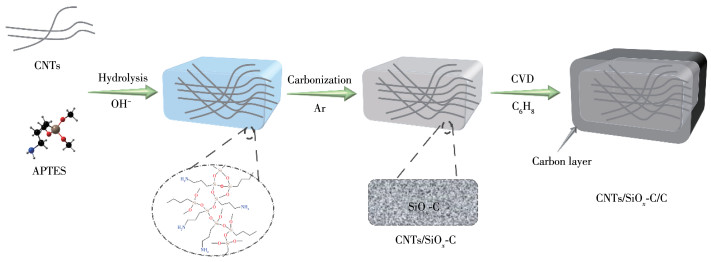
Figure 1.
Schematic diagram of the preparation processes for CNTs/SiOx-C and CNTs/SiOx-C/C

Graphite is the mainstream anode material for lithium-ion batteries (LIBs), but it is slowly failing to meet the needs of high-performance LIBs due to its low theoretical capacity (372 mAh·g-1). Although silicon-based materials have a high theoretical capacity, their huge volume expansion (ca. 300%) in the process of charge and discharge greatly reduces the cycling performance and hinders its marketization process [1-2]. In comparison, silicon oxide (SiOx, 0 < x < 2) had attracted wide attention because of its higher theoretical capacity than graphite and smaller volume expansion than elemental silicon, which is a promising anode material for the next generation of LIBs[3-4].
To alleviate the volume expansion of Si-based materials, researchers have developed several solutions, such as coating silicon-based nanomaterials with carbon or oxides (such as SiO2[5], TiO2[6]), or preparation of silicon-based nanomaterials with specific morphology. For example, Li et al. coated SiOx nanoparticles with carbon formed by asphalt pyrolysis[7]. Yang et al. constructed amorphous TiO2 shells by a facile sol-gel approach to adapt to the volume change of silicon-based material[8]. Li et al. introduced silicon-based materials onto carbon nanotubes by chemical vapor deposition (CVD) using silane gas as a silicon source[9]. Sun et al. prepared ultrathin SiOx nanosheets by solvothermal stripping of CaSi2[10]. Furthermore, researchers also found that coated Si-based materials in atomic size were a better choice compared to conventional nano-sized coating. For instance, Zhou et al. prepared atomically homogeneous SiOx/C hollow spheres by a one-pot aldimine condensation for LIB anodes, realizing the requirements of atomic-level coating and special morphology of materials at the same time[11].
Herein, we report the preparation of a composite Si-O-C material (named CNTs/SiOx-C/C) with a reinforced concrete-like structure, in which carbon nanotubes (CNTs) are embedded in the material like steel bars to provide stress support inside the material. Atomically dispersed carbon and oxygen atoms encase the silicon atoms as a buffer matrix. A carbon protection layer was further coated onto the outer layer of the material by CVD to fully mitigate the expansion effect of the material. As a result, the prepared composite material delivered stable cycle performance with a capacity retention rate of 80% after 970 cycles at a current density of 0.5 A·g-1.
Multi-walled CNTs were acquired from Xianfeng Nano Co., Ltd. 3‑Aminopropyltriethoxysilane (C9H23 NO3Si, APTES, 98%) was purchased from Bide Co., Ltd. Ammonium hydroxide (NH₃·H₂O) was purchased from Sinopharm Chemical Reagent Co., Ltd. Dichloromethane (CH2Cl2) was purchased from Sinopharm Chemical Reagent Co. Ltd., and was dried over CaH2 before use.
In a typical procedure, 100 mg of CNTs were first dispersed in 15 mL of CH2Cl2. 2 mL of NH₃·H₂O was added into the above solution and stirred for 10 minutes. Then, 2 mL of APTES was added dropwise. After stirring at room temperature overnight, the solution was left to stand and stratified rapidly. The solid was obtained by centrifugation, which was then put into tube finance and heated at 900 ℃ for 2 h with a ramping rate of 5 ℃·min-1 under Ar atmosphere to obtain CNTs/SiOx-C. To coat CNTs/SiOx-C with carbon, the product CNTs/SiOx-C was further heated under a toluene atmosphere at 800 ℃ for 2 h.
For comparison, reference materials named CNTs/SiOx-C-800 and CNTs/SiOx-C-1000 were prepared following the same procedure as CNTs/SiOx-C, but pyrolysis temperature set at 800 and 1 000 ℃, respectively. Reference materials named CNTs/SiOx‑C‑2.5 and CNTs/SiOx-C-1.5 were prepared following the same procedure as CNTs/SiOx-C, but the dosage of APTES was 2.5 and 1.5 mL, respectively.
The powder X-ray diffraction (PXRD) patterns of the prepared materials were recorded on a Bruker D8 X-ray diffractometer (Cu Kα radiation, λ=0.154 18 nm, 2θ=10°-80°, operated at 40 kV and 40 mA). Scanning electron microscope (SEM, Hitachi S4800 electron microscope, 20 kV) and transmission electron microscope (TEM, JEM-2100 microscope, 200 kV) were used to investigate the morphologies of all materials. X-ray photoelectron spectroscopy (XPS, PHI 5000V VersaProbe spectrometer) was used to investigate the surface composition of the materials. The Raman spectra of the materials were obtained on a LabRAM Aramis Raman spectrometer (Horiba, 488 nm laser). The thermogravimetric analysis (TGA) was performed on a Netzche STA449F3 from 30 to 960 ℃ under flowing air with a heating rate of 10 ℃·min-1.
The working electrode was composed of active material (Mass fraction: 70%), sodium alginate (Mass fraction: 20%), super P (Mass fraction: 10%), and copper foil as a current collector, and lithium sheets were used as counter electrodes. The load mass of the active material of all electrodes was about 0.8-1.2 mg·cm-2 after drying at 80 ℃ for 500 min under vacuum. The coin cells (CR2032-type) were assembled in an argon-filled glovebox (H2O, O2 contents were below 10-7 cm3·cm-3). Celgard 2400 membrane was used as a separator. 1 mol·L-1 LiPF6 in ethylene carbonate/dimethyl carbonate/diethyl carbonate (EC/DMC/DEC, 1∶1∶1 in volume) was used as an electrolyte.
Galvanostatic charge-discharge (GCD) measurements were carried out on a Neware battery testing device (Shenzhen, China) with a voltage window of 0.01-2 V (vs Li/Li+). Cyclic voltammetry (CV) with a voltage window of 0.01-2 V (vs Li/Li+) and a scan rate of 0.1 mV·s-1. Electrochemical impedance spectroscopy (EIS) with a frequency range from 0.01 Hz to 100 kHz was conducted on an electrochemical station (CHI650D, Shanghai Chenhua Instruments Inc., China).
Fig. 1 shows the preparation process for the material studied in this work. The commercial CNTs were used as hard templates, which were coated by inorganic and organic hybrid network structures with the atomic distribution of Si, C, and O elements through hydrolysis reaction of APTES under alkaline conditions. After calcination in inert atmosphere, composite CNTs/SiOx-C was obtained. Finally, the outer carbon layer of the material was introduced via CVD to obtain CNTs/SiOx-C/C. In this designed composite material, the internal CNTs acted as an internal skeleton, and worked together with the outermost carbon layer to relieve the volume change of the silicon-based material during the processes of charge and discharge. On the other hand, the atomically dispersed carbon and oxygen atoms formed a buffer matrix to engage silicon atoms, which also relieved the volume expansion stress from inside the material.
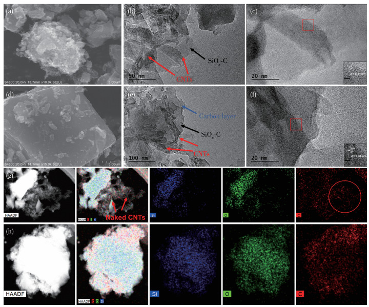
Fig. 2a, 2d, and Fig.S1 (Supporting information) depict the SEM images of CNTs/SiOx-C and CNTs/SiOx-C/C, respectively. In comparison, there were more exposed CNTs on the outer surface of CNTs/SiOx-C, and CNTs/SiOx-C/C treated with CVD had a flatter outer surface. TEM images in Fig. 2b and 2e show that CNTs/SiOx-C and CNTs/SiOx-C/C both had CNTs embedded in the amorphous material and CNTs/SiOx-C/C had a thin outer layer of carbon. High-resolution TEM (HRTEM) images of the two materials in Fig. 2c and 2f show the lattice spacing of 0.34 nm corresponding to the (002) lattice plane of graphitic CNTs (PDF No.41-1487)[12-14]. Fig. 2g depicts the TEM elemental mapping images of CNTs/SiOx-C, showing unevenly distributed Si, O, and C elements, with CNTs exposed outside the bulk material. On the other hand, the TEM elemental mapping images of CNTs/SiOx-C/C in Fig. 2h show that the C element was more widely distributed than the Si and O element, which could be contributed to the outermost carbon layer formed by CVD. In addition, the Si, O, and C elements were found evenly distributed, suggesting the formation of atomically dispersed SiOx-C composite material.
The PXRD patterns of CNTs/SiOx-C/C and CNTs/SiOx-C show the broad peaks between 20° and 35° belonging to amorphous SiOx (Fig. 3a)[15-16]. As shown in Fig. 3b and Fig.S2, both TG curves of CNTs/SiOx-C/C and CNTs/SiOx-C had a big drop from 600 to 800 ℃, which is mainly due to the combustion loss of carbon materials when heated in air (CNTs/SiOx-C/C: 37.77%, CNTs/SiOx-C: 31.63%). The mass fraction of Si element in CNTs/SiOx-C and CNTs/SiOx-C/C were 31.9% and 29.0%, respectively. Raman spectra were used to investigate the existence and crystalline state of carbon. As shown in Fig. 3c and 3d, both samples displayed two strong peaks at around 1 330 and 1 610 cm-1, attributed to the D-band and G-band of carbon material, respectively[17]. The D-band is related to the carbon atoms with dangling bonds at the edges and/or defects of the graphite carbon, while the G-band is associated with the sp2-hybridized carbon atoms[18]. The strong G band and small relative intensity ratio of the two bands (ID/IG) imply that both samples were highly graphitized[19]. In comparison, CNTs/SiOx-C/C had a smaller ID/IG ratio of 0.485 than that of CNTs/SiOx-C (0.519), illustrating that the graphitization quality of CNTs/SiOx-C/C is higher.
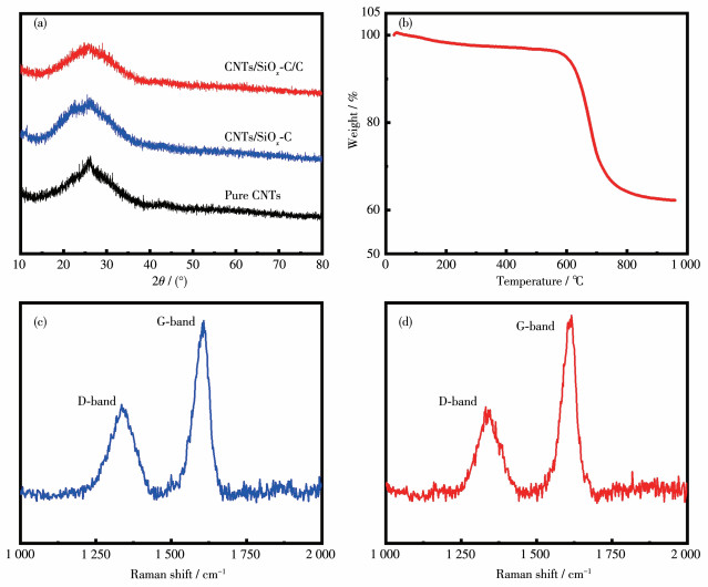
Fig. 4a and 4d show XPS spectra of CNTs/SiOx-C and CNTs/SiOx‑C/C, respectively. In comparison, CNTs/SiOx-C/C showed a stronger C1s peak and weaker O1s peak than CNTs/SiOx-C, which could be attributed to the carbon protective layer in CNTs/SiOx-C/C introduced by CVD with toluene as carbon source. The Si2p XPS spectra of CNTs/SiOx-C and CNTs/SiOx-C/C both displayed peaks around 103 eV (Fig. 4b, 4e), which could be deconvoluted into three peaks at 102.3, 103.1, and 103.8 eV in CNTs/SiOx-C (Fig. 4b), and at 102.0, 102.7, and 103.5 eV in CNTs/SiOx-C/C (Fig. 4e) owing to Si2+, Si3+, and Si4+, respectively[20-21]. The C1s XPS spectra of CNTs/SiOx-C (Fig. 4c) and CNTs/SiOx-C/C (Fig. 4f) could be deconvoluted to the sp2 C (283.6 eV), sp3 C (284.4 eV), C—CO (285.5 eV), and COOC (288.5 eV) (Fig. 4c), sp2 C (283.6 eV), sp3 C (284.5 eV), C—CO (285.8 eV), and COOC (288.8 eV) (Fig. 4f), respectively[22]. The high intensities of the sp2 C peaks imply high graphitization quality in both materials, while weaker relative intensities of the oxygen-binding C peaks in CNTs/SiOx-C/C are due to the CVD carbon layer on the particle surface.
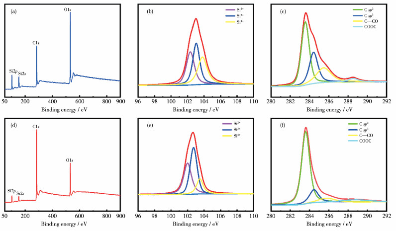
Fig. 5a and 5b show the GCD curves of CNTs/SiOx-C and CNTs/SiOx-C/C electrodes at the current density of 0.1 A·g-1 with a potential window from 0.01 to 2 V. Both curves showed irreversible capacity change after comparing the discharge charge curve of the first circle, which are consistent with their CV curves (Fig.S3). The GCD results illustrated that CNTs/SiOx‑C and CNTs/SiOx-C/C electrodes both had relatively low initial coulombic efficiency (both were about 50%), which mainly could be contributed to the formation of the solid-electrolyte interphase (SEI) layer and side reactions[23-24]. Fig. 5c and 5d show the rate performance of CNTs/SiOx‑C and CNTs/SiOx‑C/C electrodes. The CNTs/SiOx-C electrode delivered specific charge capacities of 662, 573, 488, 395, and 330 mAh·g-1 at the current densities of 0.1, 0.2, 0.4, 0.8, and 1.2 A·g-1, respectively. On the other hand, the CNTs/SiOx‑C/C electrode displayed specific charge capacities of 620, 527, 434, 345, and 278 mAh·g-1 at the current densities of 0.1, 0.2, 0.4, 0.8, and 1.2 A·g-1, respectively. Both electrodes recovered after the current density changed back to 0.1 A·g-1, with a high-capacity retention of 86.0% (569 mAh·g-1) for CNTs/SiOx‑C electrode and 94.4% (585 mAh·g-1) for CNTs/SiOx‑C/C electrode. It is noted that the pure CNTs electrode prepared under similar conditions had a charge capacity of 280 mAh·g-1 at 0.1 A·g-1 (Fig.S4), suggesting that the specific capacities of CNTs/SiOx-C and CNTs/SiOx-C/C are mainly due to SiOx species.
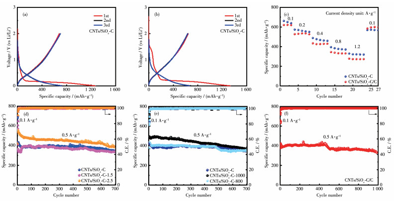
Fig. 5d shows the effects of different dosage ratios of APTES and CNTs on the electrochemical properties of electrode materials. The CNTs/SiOx‑C electrode delivered a reversible capacity of about 681 mAh·g-1, and a capacity retention rate of 80% after 700 cycles at 0.5 A·g-1. In comparison, the charge capacity the of CNTs/SiOx-C-2.5 electrode was 771 mAh·g-1, and the capacity retention rate was 68.7% at the 700th cycle, the CNTs/SiOx-C-1.5 electrode showed a reversible capacity about 605 mAh·g-1 and a capacity retention rate 92.4% at 700th cycle. Fig. 5e shows the long-term cycling performance of CNTs/SiOx-C electrode, compared with those of CNTs/SiOx-C-1000 electrode and CNTs/SiOx-C-800 electrode prepared at different pyrolysis temperatures. The cycling performance of CNTs/SiOx-C was better than the CNTs/SiOx-C-1000 (74%) and CNTs/SiOx-C-800 (79%) electrodes. The results suggest that the pyrolysis temperature of 900 ℃ was optimal for the material preparation. The poorer performance of the materials prepared at lower or higher temperatures might be due to less graphitized carbon or lower surface area due to sintering. In comparison, the CNTs/SiOx-C/C electrode delivered a capacity retention rate of 80% after 970 cycles at 0.5 A·g-1 (Fig. 5f), better than the CNTs/SiOx-C electrode. The SEM images of CNTs/SiOx-C and CNTs/SiOx-C/C electrodes before and after 300 cycles at a current density of 0.5 A·g-1 were taken to further evaluate the structural stability of two anode materials (Fig.S5). Consistent with the cycling performance of the two electrodes (Fig. 5f), the cycled CNTs/SiOx‑C electrode showed obvious cracks, while the CNTs/SiOx‑C/C electrode showed an intact flatten surface. The improved cycling performance of the CNTs/SiOx-C/C electrode could be attributed to the additional carbon layer on the particle surface of CNTs/SiOx-C/C prepared by CVD coating, which served as a protection against the volume change during the charge and discharge processes.
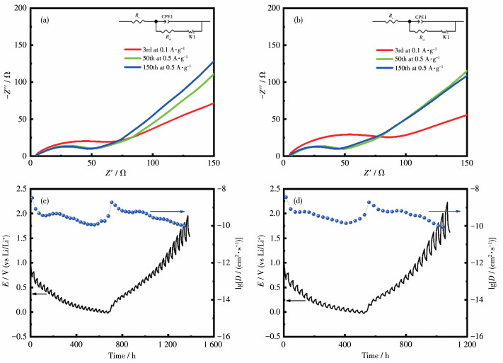
EIS analyses were used to evaluate the conductivity of the CNTs/SiOx‑C and CNTs/SiOx‑C/C electrodes[25]. As shown in Fig. 6a and 6b, the Nyquist plots for both electrodes display a typical semicircle with a sloping low-frequency line. The semicircle represents the charge-transfer resistance (Rct) at the electrolyte interface and the low-frequency line represents the Warburg impedance (W1) which is indicative of the Li+ diffusion. Rs represents the ohmic impedance of electrolyte and battery components and CPE1 represents constant[26-27]. The Rct of the CNTs/SiOx-C electrode was calculated as 57.09 Ω at the 3rd cycle at 0.1 A·g-1 and reduced to 39.84 Ω at the 50th cycle, and 39.86 Ω at the 150th cycle at 0.5 A·g-1. The charge-transfer resistance of the CNTs/SiOx-C/C electrode was smaller, with the Rct of 44.73, 33.41, and 26.94 Ω at the 3rd, 50th, and 150th cycle, respectively. Constant current intermittent titration technique (GITT) was further used to investigate the lithium-ion diffusion kinetics of the CNTs/SiOx-C and CNTs/SiOx-C/C electrodes during the discharge and charge processes. As shown in Fig. 6c and 6d, the calculated lithium ions diffusion coefficients of the CNTs/SiOx-C electrode ranged from 3.30×10⁻⁹ to 9.96×10⁻¹¹ cm2·s-1, while the ones of the CNTs/SiOx-C/C electrode ranged from 3.57×10⁻⁹ to 8.62×10⁻¹¹ cm2·s-1, which were higher than many reported SiOx-based anode material[28-31]. The smaller charge-transfer resistance and higher lithium ions diffusion coefficients of the CNTs/SiOx-C/C electrode indicate unobstructive electronic and Li+ pathways owing to higher crystallized graphitic carbon layer on the particle surface.
We prepared SiOx-C composites by using a reinforced concrete structure concept for alleviating the volume changes of the SiOx anodes. The composites were composed of atomically dispersed carbon, oxygen, and silicon matrixes with embedment of carbon nanotubes, which were further coated with carbon layer on the outer surface by CVD. Thanks to the multiple and uniform protection of silicon atoms, the prepared CNTs/SiOx-C/C composite delivered a high-capacity retention rate of 80% after 970 cycles at 0.5 A·g-1. This work provides a feasible means to prepare SiOx-C composites for high-performance lithium-ion batteries.
Li Y Z, Yan K, Lee H W, Lu Z D, Liu N, Cui Y. Growth of conformal graphene cages on micrometre-sized silicon particles as stable battery anodes[J]. Nat. Energy, 2016, 1(2): 15029. doi: 10.1038/nenergy.2015.29
Zhang H, Zong P, Chen M, Jin H, Bai Y, Li S W, Ma F, Xu H, Lian K. In situ synthesis of multilayer carbon matrix decorated with copper particles: enhancing the performance of Si as anode for Li-ion batteries[J]. ACS Nano, 2019, 13(3): 3054-3062. doi: 10.1021/acsnano.8b08088
Yang W, Liu H, Ren Z H, Jian N, Gao M X, Wu Y J, Liu Y F, Pan H G. A novel multielement, multiphase, and B-containing SiOx composite as a stable anode material for Li-ion batteries[J]. Adv. Mater. Interfaces, 2019, 6(5): 1801631. doi: 10.1002/admi.201801631
Shi L R, Pang C L, Chen S L, Wang M H, Wang K X, Tan Z J, Gao P, Ren J G, Huang Y Y, Peng H L, Liu Z F. Vertical graphene gowth on SiO microparticles for stable lithium ion battery anodes[J]. Nano Lett., 2017, 17(6): 3681-3687. doi: 10.1021/acs.nanolett.7b00906
Tang C J, Liu Y N, Xu C, Zhu J X, Wei X J, Zhou L, He L, Yang W, Mai L Q. Ultrafine nickel-nanoparticle-enabled SiO2 hierarchical hollow spheres for high-performance lithium storage[J]. Adv. Funct. Mater., 2018, 28(3): 1704561. doi: 10.1002/adfm.201704561
Zhou N, Wu Y F, Zhou Q, Li Y R, Liu S H, Zhang H B, Zhou Z, Xia M. Enhanced cycling performance and rate capacity of SiO anode material by compositing with monoclinic TiO2(B)[J]. Appl. Surf. Sci., 2019, 486: 292-302. doi: 10.1016/j.apsusc.2019.05.025
Li G, Li J Y, Yue F S, Xu Q, Zuo T T, Yin Y X, Guo Y G. Reducing the volume deformation of high capacity SiOx/G/C anode toward industrial application in high energy density lithium-ion batteries[J]. Nano Energy, 2019, 60: 485-492. doi: 10.1016/j.nanoen.2019.03.077
Yang J P, Wang Y X, Li W, Wang L J, Fan Y C, Jiang W, Luo W, Wang Y, Kong B, Selomulya C, Liu H K, Dou S X, Zhao D Y. Amorphous TiO2 shells: A vital elastic buffering layer on silicon nanoparticles for high-performance and safe lithium storage[J]. Adv. Mater., 2017, 29(48): 1700523. doi: 10.1002/adma.201700523
Ma T Y, Xu H Y, Yu X G, Li H Y, Zhang W G, Cheng X L, Zhu W T, Qiu X P. Lithiation behavior of coaxial hollow nanocables of carbonsilicon composite[J]. ACS Nano, 2019, 13(2): 2274-2280.
Sun L, Su T T, Xu L, Liu M P, Du H B. Two-dimensional ultra-thin SiOx (0<x<2) nanosheets with long-term cycling stability as lithium ion battery anodes[J]. Chem. Commun., 2016, 52(23): 4341-4344. doi: 10.1039/C6CC00723F
Zhou X M, Liu Y, Ren Y, Mu T S, Yin X C, Du C Y, Huo H, Cheng X Q, Zuo P J, Yin G P. Engineering molecular polymerization for template-free SiOx/C hollow spheres as ultrastable anodes in lithiumion batteries[J]. Adv. Funct. Mater., 2021, 31(21): 2101145. doi: 10.1002/adfm.202101145
Chen R X, Zhou Y C, Li X D. Cotton-derived Fe/Fe3C-encapsulated carbon nanotubes for high-performance lithium-sulfur batteries[J]. Nano Lett., 2022, 22(3): 1217-1224. doi: 10.1021/acs.nanolett.1c04380
Zeng Y X, Zhang X Y, Qin R F, Liu X Q, Fang P P, Zheng D Z, Tong Y X, Lu X H. Dendrite-free zinc deposition induced by multi-functional CNT frameworks for stable flexible Zn-ion batteries[J]. Adv. Mater., 2019, 31(36): e1903675. doi: 10.1002/adma.201903675
Zhang Y P, Wang L L, Xu H, Gao J M, Chen D, Han W. 3D chemical cross-linking structure of black phosphorus@CNTs hybrid as a promising anode material for lithium ion batteries[J]. Adv. Funct. Mater., 2020, 30(12): 1909372. doi: 10.1002/adfm.201909372
Xu Q, Sun J K, Li G, Li J Y, Yin Y X, Guo Y G. Facile synthesis of a SiOx/asphalt membrane for high performance lithium-ion battery anodes[J]. Chem. Commun., 2017, 53(89): 12080-12083. doi: 10.1039/C7CC05816K
Guo X T, Li W T, Geng P B, Zhang Q Y, Pang H, Xu Q. Construction of SiOx/nitrogen-doped carbon superstructures derived from rice husks for boosted lithium storage[J]. J. Colloid Interf. Sci., 2022, 606(1): 784-792.
Chen X C, Kierzek K, Jiang Z W, Chen H M, Tang T, Wojtoniszak M, Kalenczuk R J, Chu P K, Borowiak-Palen E. Synthesis, growth mechanism, and electrochemical properties of hollow mesoporous carbon spheres with controlled diameter[J]. J. Phys. Chem. C, 2011, 115(36): 17717-17724. doi: 10.1021/jp205257u
Pimenta M A, Dresselhaus G, Dresselhaus M S, Cancado L G, Jorio A, Saito R. Studying disorder in graphite-based systems by Raman spectroscopy[J]. Phys. Chem. Chem. Phys., 2007, 9(11): 1276-1291. doi: 10.1039/B613962K
Sasikala S P, Henry L, Yesilbag Tonga G, Huang K, Das R, Giroire B, Marre S, Rotello V M, Penicaud A, Poulin P, Aymonier C. High yield synthesis of aspect ratio controlled graphenic materials from anthracite coal in supercritical fluids[J]. ACS Nano, 2016, 10(5): 5293-5303. doi: 10.1021/acsnano.6b01298
Lim K, Park H, Ha J, Kim Y T, Choi J. Dualcarbon-confined hydrangea-like SiO cluster for high-performance and stable lithium ion batteries[J]. J. Ind. Eng. Chem., 2021, 101: 397-404. doi: 10.1016/j.jiec.2021.05.043
Guo L, He H, Ren Y, Wang C, Li M. Core-shell SiO@F-doped C composites with interspaces and voids as anodes for high-performance lithium-ion batteries[J]. Chem. Eng. J., 2018, 335: 32-40. doi: 10.1016/j.cej.2017.10.145
Kim S J, Kim M C, Han S B, Lee G H, Choe H S, Moon S H, Kwak D H, Hong S, Park K W. 3-D Si/carbon nanofiber as a binder/current collector-free anode for lithium-ion batteries[J]. J. Ind. Eng. Chem., 2017, 49: 105-111. doi: 10.1016/j.jiec.2017.01.014
Jang J Y, Kang I, Choi J K, Jeong H, Yi K W, Hong J Y, Lee M. Molecularly tailored lithium-arene complex enables chemical prelithiation of high-capacity lithium-ion battery anodes[J]. Angew. Chem. Int. Ed., 2020, 59(34): 14473-14480. doi: 10.1002/anie.202002411
Raza A, Jung J Y, Lee C H, Kim B G, Choi J H, Park M S, Lee S M. Swelling-controlled double-layered SiOx/Mg2SiO4/SiOx composite with enhanced initial coulombic efficiency for lithium-ion battery[J]. ACS Appl. Mater. Inter., 2021, 13(6): 7161-7170. doi: 10.1021/acsami.0c19975
Wang C, Wu H, Chen Z, McDowell M T, Cui Y, Bao Z N. Self-healing chemistry enables the stable operation of silicon microparticle anodes for high-energy lithium-ion batteries[J]. Nat. Chem., 2013, 5(12): 1042-1048. doi: 10.1038/nchem.1802
Tokur M, Jin M Y, Sheldon B W, Akbulut H. Stress bearing mechanism of reduced graphene oxide in silicon-based composite anodes for lithium ion batteries[J]. ACS Appl. Mater. Inter., 2020, 12(30): 33855-33869. doi: 10.1021/acsami.0c10064
Ian B, Ji W. Asymmetric membranes containing micron-size silicon for high performance lithium ion battery anode[J]. Electrochim. Acta, 2016, 213: 46-54. doi: 10.1016/j.electacta.2016.07.106
Shi H B, Shao G Q, Wu B B, Yang Z X, Zhang H G, Lv P P, Zhu Q S. Scalable synthesis of a dual-confined SiO/one-dimensional carbon/amorphous carbon anode based on heterogeneous carbon structure evolution[J]. J. Mater. Chem. A, 2021, 9(46): 26236-26247. doi: 10.1039/D1TA07821F
Chen S Y, Xu Y N, Du H B. One-step synthesis of uniformly distributed SiOx-C composites as stable anodes for lithium-ion batteries[J]. Dalton Trans., 2022, 51(31): 11909-11915. doi: 10.1039/D2DT01843H
Fu R S, Ji J J, Yun L, Jiang Y B, Zhang J, Zhou X F, Liu Z P. Graphene wrapped silicon suboxides anodes with suppressed Li-uptake behavior enabled superior cycling stability[J]. Energy Stor. Mater., 2021, 35: 317-326.
Li H, Peng J, Wu Z Y, Liu X L, Liu P, Chang B B, Wang X Y. Constructing novel SiOx hybridization materials by a double-layer interface engineering for high-performance lithium-ion batteries[J]. Chem. Eng. J., 2023, 462: 142172. doi: 10.1016/j.cej.2023.142172

Figure 1 Schematic diagram of the preparation processes for CNTs/SiOx-C and CNTs/SiOx-C/C

Figure 2 (a) SEM, (b) TEM, and (c) HRTEM images of CNTs/SiOx-C; (d) SEM, (e) TEM, and (f) HRTEM images of CNTs/SiOx-C/C; TEM mapping images of (g) CNTs/SiOx-C and (h) CNTs/SiOx-C/C

Figure 3 (a) PXRD patterns of CNTs/SiOx-C/C, CNTs/SiOx-C, and pure CNTs; (b) TG curve of CNTs/SiOx-C/C; Raman spectra of (c) CNTs/SiOx-C and (d) CNTs/SiOx-C

Figure 4 XPS spectra of (a-c) CNTs/SiOx-C and (d-f) CNTs/SiOx-C/C: (a, d) full spectra; (b, e) Si2p region; (c, f) C1s region

Figure 5 GCD profiles of (a) CNTs/SiOx-C and (b) CNTs/SiOx-C/C electrodes for the first three cycles at 0.1 A·g-1; (c) Rate performance of CNTs/SiOx-C and CNTs/SiOx-C/C electrodes; (d) Long-term cycling performance of the CNTs/SiOx-C, CNTs/SiOx-C-2.5, CNTs/SiOx-C-1.5 electrodes; (e) Long-term cycling performance of the CNTs/SiOx-C, CNTs/SiOx-C-1000, CNTs/SiOx-C-800 electrodes; (f) Long-term cycling performance of CNTs/SiOx-C/C electrode

 扫一扫看文章

扫一扫关注我们
 下载:
下载:
 下载:
下载:
