Figure 1.
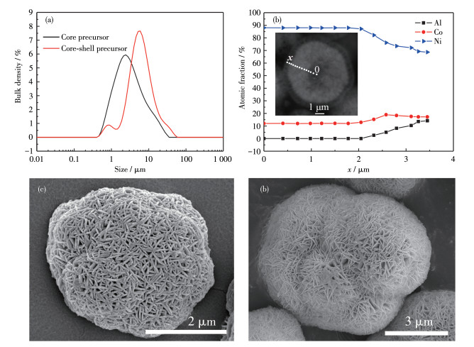
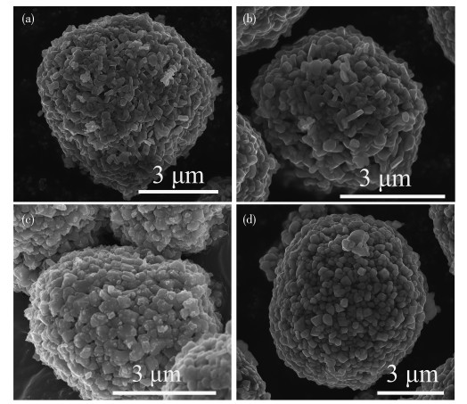
(a) PSA data of the precursors, (b) EPMA point scans for core-shell precursor (Inset: cross-section SEM image), and SEM mages for (c) core precursor and (d) core-shell precursor

Li-ion battery (LIB) has been widely used as energy storage systems (ESS) for electric vehicles (EVs) due to its cathode material with high energy densities, no memory effect, and low self-discharge. LiNi0.80Co0.15Al0.05O2 (NCA) belongs to layered nickel-rich lithium oxide and has been successfully used in Tesla's new energy vehicle, but it still has some problems to overcome. For example, poor thermal and structural instabilities of NCA are potential security issues for EVs, which severely restrict its commercial application. In general, the structure of NCA can trigger reversible phase transformation from layered (R3m) to spinel (Fd3m) during charge-discharge cycles. In practice, a few percent of spinel (Fd3m) phases will further charge to irreversible NiO-like phase (Fm3m) phase because of structural instabilities and overcharge, resulting in the evolution of O2 and CO2 gas[1-3]. This process accompanies a lattice distortion and volume charge, which leads to cracks. And this phenomenon will become more serious as nickel content increases. Numerous efforts have proved that the Ni-deficient surface of NCA is helpful to reduce anisotropic volume variations during cycling and electrolyte attacks of the Ni-rich composition, such as coating layer (Li2TiO3, Li2O-2B2O3, Zr2O2, et al.) on its surface[2-5] or metal (such as W, Zr, Ti, Nb) doping on NCA[6-8]. Nevertheless, both of them can lead to reversible capacity fade. Moreover, NCA material with surface coating exhibits a sharp composition change and a crystal mismatch in the NCA-coating layer interface, which causes micro gaps by volume shrinkage on cycling[9-10].
To overcome the shortcomings of Ni-rich cathode materials, a gradient variation of transition metals in the material is demonstrated as an effective structure to enhance its thermal stability and cycle life without reducing the reversible capacity of NCA materials[10-18]. The Ni-rich core of concentration-gradient material delivers a serviceable high initial capacity, whereas the surface layer with Ni-poor and Al-rich enhances thermal and structural stability upon the charging and discharging process[8, 11]. At the same time, this material exhibited a smooth composition change of Ni, Co, and Al from the core to the surface, suggesting a well-structural match between the Ni-rich core and Ni-deficient layer[12-19]. Usually, concentration-gradient material is obtained by sintering concentration-gradient precursor or core-shell precursor. For the former, the pH value of the synthetic process is always fluctuating due to the continuous composition variation of transition metals injected into the reactor, which may easily cause element micro-segregation and make the preparation process out of control[10, 16-18]. For core-shell precursors, the pH value of the reaction is quite stable, which is easy to obtain precursors uniformly and efficiently[10-11, 19-21]. In this study, the concentration-gradient structure for NCA is controlled by the calcination time of a core-shell precursor. That is because the degree of disorder of Li+ and Ni2+ which is cased closely correlated with calcination temperature increasing as the Ni content increasing. And an Al-rich surface layer may generate a large electrochemical resistance due to the electrochemical inactivity of Al. Therefore, the concentration distribution of Ni, Co, and Al in NCA is closely correlated with its capacity and structure stability[16-19]. In the practice of synthetic technology, the concentration-gradient structure of NCA designed by the calcination process is much more controllable and easier in comparison to the co-precipitation process.
In our previous work[19-21], a new design Ni0.80Co0.15Al0.05(OH)2 precursor was successfully synthesized by adjusting the Al solution at three flow rates. This precursor had a core-shell structure, which can be designed by the co-precipitation process, such as the thickness of gradient layers and the chemical composition of the core and the shell. Numerous studies have shown that NCA is sensitive to sintering temperature[5-7]. If this temperature is too high, it will cause a significant cation disorder of Li+/Ni2+ in materials. If the sintering temperature is too low, the structural evolution of gradient NCA material is incomplete. In both cases, gradient NCA shows poor electrochemical performance. In general, the sintering temperature of NCA should not be above 750 ℃ when Ni atomic fraction is 0.80 and will decrease with Ni atomic fraction increasing[5-7, 19-21]. In this study, we design the concentration-gradient structure of NCA by sintering time, electron-probe X-ray microanalyzer (EPMA) point analysis, thermogravimetric, and differential scanning calorimetry analysis (TG-DSC), X-ray diffraction (XRD), X-ray photoelectron spectroscopy (XPS), and cell test were examined to explain why the concentration-gradient structure can greatly enhanced electrochemical properties and structural stability.
The methods to prepare core-shell structure precursor were described in our previous articles[19-21]. A mixed salt solution with Ni and Co in a molar ratio (nNi∶nCo) of 0.88∶0.12 and an alkali liquor (2 mol·L-1 NaOH and 1.2 mol·L-1 ammonia) were injected into a continuously stirred tank reactor (CSTR) and a reaction temperature was controlled at 50 ℃. The alkali liquor was used to adjust the pH value of the reaction at 11.5±0.05 online. After 15 h of reaction, the slurry was filtered to obtain a core precursor. The core precursor was mixed with 1 L 0.4 mol·L-1 ammonia, which was used as a starting solution in CSTR to synthesize the shell of the precursor. Another Ni-Co solution with a nNi∶nCo of 0.88∶0.12, an Al solution obtained by dissolved NaAlO2 in a 0.05 mol·L-1 NaOH solution, and an alkali liquor (2 mol·L-1 NaOH and 1.0 mol·L-1 ammonia) were pumped into CSTR. The pH value was adjusted at 10.5±0.05 by the alkali liquor. The Al solution was firstly injected at 0.036 L·h-1 for 3 h, then 0.072 L·h-1 for 3 h, and finally 0.108 L·h-1 for 3 h, while Ni-Co salt solution was pumped at a constant rate. After 9 h, the co-precipitation reaction ended, and the molar ratio of Ni, Co, and Al in the out-layer was 0.72∶0.18∶10. According to the experiment, the composition of three shells (out-layer) was about Ni0.75Co0.19Al0.06(OH)2, Ni0.72Co0.18Al0.10(OH)2, and Ni0.69Co0.17Al0.14(OH)2. The total molar ratio of transition metals in the first and second co-precipitation was 0.5∶0.5. The composition of the core-shell precursor was [Ni0.88Co0.12(OH)2]0.5[Ni0.72Co0.18Al0.10(OH)2]0.5. This prepared core-shell precursor and LiOH·H2O were mixed in a molar ratio of 1∶1.05, and was calcined at 550 ℃ for 4 h and then at 700 ℃ for 6, 9, 12, and 15 h in O2 flow, respectively. The full gradient NCA materials were obtained and marked as GNCA-6, GNCA-9, GNCA-12, and GNCA-15.
Particle size analysis (PSA) of the precursor was determined by a laser particle size analyzer. The precursor powder was dispersed in 1% (NaPO3)6 solution by ultrasonic dispersion for 5 min and then was determined by Mastersizer 3000 (refractive indexes of particle and solution were 1.800 and 1.330, respectively). The tap density of the sample was tested by a powder comprehensive characteristic tester (BT-1000, Better) with a vibration time of 6 min. The chemical composition of the sample was analyzed by inductively coupled plasma atomic emission spectroscopy (ICP-OES, PE, AVIO200, 1 300 W, Ar flow of 12 L·min-1). The thermal property of the mixture of core-shell precursor and LiOH·H2O with a molar ratio of 1∶1.05 was analyzed by TG-DSC (Netzsch, STA449F3) at a heating rate of 5 ℃·min-1 in O2 flow of 20 mL·min-1. XRD (Bruker D8 Discover, 40 kV, 40 mA) with Cu Kα radiation (λ=0.154 18 nm) was used to adapt for the crystalline phase of the obtained powders. The 2θ range was from 10° to 90° with a scanning rate of 5 (°)·min-1. The XRD pattern was refined by GSAS-EXPGUI software. Particle morphologies and microstructure observation were characterized by scanning electron microscope (SEM, ThermpFisher) with an accelerating voltage of 10 kV. Point scans of the polished surface for materials were analyzed by an EPMA (JXA-8100, JEOL). The valence states and relative amounts based on the surface compositions of gradient NCA powders were determined by XPS (Thermo Fisher, Escalab Xi+). The morphology of the electrode surface after the 200th cycle was observed by SEM.
For cathode fabrication, a mixture with 80% gradient NCA powders, 10% acetylene black, and 10% polyvinylidene difluoride (PVDF) was blended in N-methyl pyrrolidone to form a slurry. The mixed slurry was spread onto Al-foil and dried in a vacuum at 120 ℃ for 12 h. Li foil (as an anode), Al-foil with active material (as a cathode), Celgard 2500 (as a separator), and electrolyte (a 1 mol·L-1 LiPF6 solution in a 1∶1∶1 (V/V) mixture of ethylene carbonate (EC) / diethyl carbonate (DEC) / dimethyl carbonate (DMC) solvent) were assembled into CR2032 coin-type half cells in an argon-filled glove box. The electrochemical performance test of the fabricated coin cells was performed at 25 ℃ between 2.8 and 4.3 V. Preliminary cell formation consisted of 7 cycles at 0.2C (1C=180 mA·g-1), and then the cells were charged at 0.2C and discharged at 1C for 193 cycles. The rate performance tests of the samples: The assembled batteries were charged at 0.2C and discharged at 0.2C, 0.5C, 1C, 3C, 5C, 10C, and 0.2C for 10 cycles respectively. Electrochemical impedance spectroscopy (EIS) tests were investigated between 0.1 Hz and 100 kHz with a amplitude of 5 mV.
Fig. 1a presents PSA data of precursors. The average diameter of the core-shell precursor was 6.16 μm, and it increased to about 2.06 μm more than the core precursor. This is accurately suggesting that Ni, Co, and Al were uniformly deposited on the surface of the core precursor and form a multiple-shell structure. Fig. 1b shows that the core-shell precursor was quite close to the designed composition. The relative atomic ratio of Ni/Co remained almost constant from the core center to about x=2.0 μm, indicating that the core of the precursor was a uniform structure and was quite close to the designed composition of Ni0.88Co0.12(OH)2. After this point (area labeled "shell"), Al atomic fraction increased steadily from 0.001 to 0.141 and Ni atomic fraction gradually decreased from 0.881 to 0.687 at the particle surface, while Co atomic fraction firstly increased from 0.120 to 0.189 (x=2.0-2.6 μm) and then decreased to 0.172 (the surface), resulting in a particle surface composition of Ni0.687Co0.172Al0.141(OH)2 based on EPMA. The surface composition of the core-shell precursor matched well with the design structure. The cross-section image (Inset in Fig. 1b) confirmed that precursor particles were core-shell structures and the concentration-gradient shell thickness was about 1.52 μm. As shown in Fig. 1c and 1d, it was clear that both particles had a spherical morphology and were conglobated by primary nano-flakes, resulting in flower-like microspheres. It was observed that the particle contained many spaces between grains, which would lead to a low tap density of LiNi0.80Co0.15Al0.05O2. It is helpful to increase the reaction time of the precursor to obtain more compact particles.
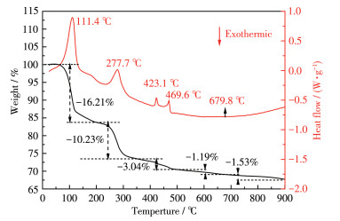
Many studies have proved that the synthesis temperature of NCA (Ni atomic fraction was at least 0.80) should be less than 750 ℃ or the cathode material has a poor electrochemical performance[4-9]. The TG-DSC curves of the mixture of core-shell precursor and LiOH·H2O are shown in Fig. 2.
The weight loss of the mixture included five parts. Before 200 ℃, the weight loss was 16.21% and the endothermic peak appeared at approximately 111.4 ℃. In this part, LiOH·H2O lost its crystal water[7]: LiOH·H2O=LiOH+H2O. The theoretical mass reduction of this reaction was 13.98%, which was less than 16.21%. Hydroxide is a moisture-absorbing material. There was about 2.23% absorbed water in the mixture. The weight loss (10.23%) at 200-350 ℃ was the decomposition of the core-shell precursor, corresponding to the endothermic peak at 277.7 ℃ on the DSC curve. The theoretical mass reduction of this reaction was 12.97% (including 2.23% absorbed water in the mixture). The test value was 78.87% of the theoretical mass reduction value. It was close to the molar ratio of Ni (0.80) in the core-shell precursor, suggesting that it was the decomposition of hydroxide radical corresponding to Ni in the precursor[7]. A core-shell precursor was not decomposed completely in this temperature range. In the range of 350-500 ℃, there were two endothermic peaks on the DSC curve, corresponding to two reactions: the complete decomposition of precursor (at 423.1 ℃) with 3.04% weight loss and the melting of LiOH (at 469.6 ℃) without weight loss. It was the decomposition of hydroxyl radical corresponding to Co and Al of precursor. This weight loss (13.27%) at the range of 200-500 ℃ was found to be quite close to the theoretical weight loss value of complete decomposition of core-shell precursor (12.97%). Ni has a higher electronegativity than Co and Al, implying that Ni2+ is easier to attract the outer-sphere electron of O (the bond strength for Ni—O is stronger than that for the Co—O bond and Al—O bond)[7]. The hydroxide radical that existed in the core-shell precursor turns into a hydrogen bond, which weakens the stability of the chemical bond in the precursor[7]. Therefore, the decomposition temperature of the hydroxide radical corresponding to Ni was lower than the one corresponding to Co and Al. Additionally, the decomposition temperature of hydroxide radical in precursor increased with decreasing OH- concentration. In 500-650 ℃, the weight loss (1.19%) was the loss of lattice water between the reaction of LiOH and Ni0.80Co0.15Al0.05O2 (2LiOH+2Ni0.80Co0.15Al0.05O+1/2O2=2LiNi0.80Co0.15Al0.05O2+H2O), which was higher than theoretical mass reduction (0.76%). The range of 650-900 ℃ corresponds to 1.53% weight loss. Here, it corresponds to the structural evolution of gradient NCA materials without weight loss. The loss of oxygen and lithium of NCA was a result of high sintering temperatures. Therefore, the sintering temperature should be less than 750 ℃ for NCA (Ni atomic fraction was at least 0.8), while the weight loss was 0.57% at 650-750 ℃.
The mixture of the core precursor and LiOH·H2O (in a molar ratio of 1∶1.05) was calcined at 550 ℃ for 4 h and then at 680, 700, 720, 750, 780, and 800 ℃ for 12 h in O2 flow, respectively. The prepared LiNi0.88Co0.12O2 materials were analyzed by XRD and the results were shown in Fig.S1 (Supporting information). All the diffraction peaks of samples could be indexed based on the layered α-NaFeO2 (PDF No.09-0063) structure. When the sintering temperature was controlled at 680-750 ℃, the clear splits in (006)/(102) peaks and (108)/(110) peaks were observed, meaning that the sample had a well-developed layer structure[11]. I(003)/I(104) (the intensity ratio of (003) to (104) planes) value has been used to estimate the qualitative degree of cation mixing between Li+ and Ni2+ in the lithium layered[13-16]. Generally, values lower than 1.3 means a significant degree of Li+/Ni2+ mixing[13-16]. The Ni2+ ions which occupancies in the Li+ layer not only impede Li+ diffusivity but also decrease the reversible capacity of cathode materials. The I(003)/I(104) values of materials were 1.539, 1.549, 1.267, 1.175, 1.086, and 0.703 with the calcining temperature increasing from 680 to 800 ℃, respectively. To have a high capacity, the synthesis temperature of this material should be 680-700 ℃.
Combination of the TG-DSC and XRD results, the temperature of structural evolution of gradient NCA materials should be at 680-700 ℃, following kinds of literature[5, 11, 17-19]. In this calcination temperature range, the structural evolution of gradient NCA material was complete and the weight loss was less than 0.57%. Therefore, the mixture of core-shell precursor and LiOH·H2O was first preheated at 550 ℃ for 4 h with a substantially complete reaction of LiOH·H2O and Ni0.80Co0.15Al0.05(OH)2 and subsequently was sintered at 700 ℃ for 6-15 h with the structural evolution of the NCA cathode material.
Table S2 lists the total chemical concentration of the gradient materials, which is found to be LiNi0.80Co0.15Al0.05O2. Fig. 3 shows the atomic fractions of Ni, Co, and Al in gradient NCA materials. From the core center (x=0) to the particle surface, Ni atomic fractions for GNCA-6, GNCA-9, GNCA-12, and GNCA-15 decreased gradually from 0.870 to 0.704, 0.861 to 0.714, 0.855 to 0.732, and 0.846 to 0.759 respectively, and the Al atomic fraction increased steadily from 0.000 to 0.134, 0.001 to 0.128, 0.003 to 0.115, and 0.009 to 0.089 respectively; while Co atomic fraction for GNCA-6 increased from 0.130 to 0.175 (x=0-2.16 μm) (Co atomic fraction for GNCA-9, GNCA-12, and GNCA-15 were 0.138 to 0.170 with x=0-2.72 μm, 0.142 to 0.163 with x=0-2.72 μm, and 0.146 to 0.159 with x=0-1.99 μm) and then decreased gradually to 0.161 (the particle surface) (that one for GNCA-9, GNCA-12, and GNCA-15 were 0.157, 0.153, and 0.152 respectively).
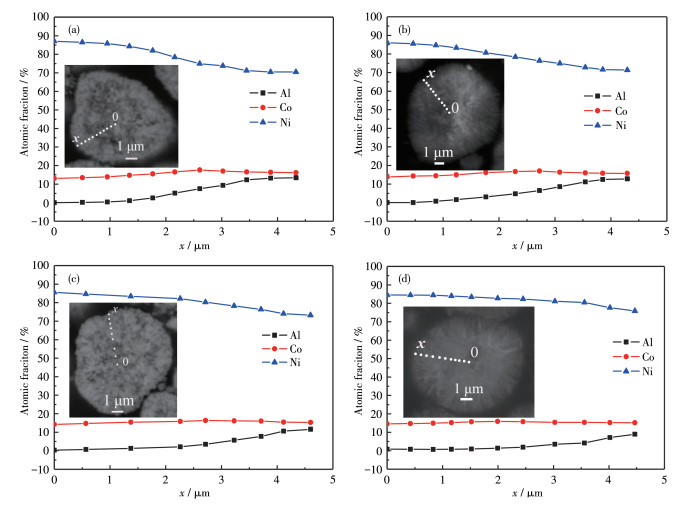
Inset: corresponding cross-section SEM images
As expected, the concentration-gradient NCA showed different concentration charges of Ni, Co, and Al in materials under different calcination times, accurately suggesting that the degree of variation of transition metals for cathode materials was decreased with the extended holding time. The gradual and continuous concentration shifting of Ni (decreasing) and electrochemically inactive Al (increasing) on the surface of NCA gave rise to enhanced layered stability during the cycling process[3-6]. The time for the calcination process should not be too long or the concentration-gradient NCA will turn into a homogeneous material.
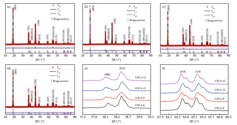
XRD patterns of cathode powders, as well as the corresponding refinement calculated data performed with the GSAS software package, are displayed in Fig. 4. All the peaks could be indexed based on the layered α-NaFeO2 (PDF No.09-0063) structure with an R3m space group. As shown in Fig. 4e and 4f, the clear splits in (006)/(102) and (108)/(110) peaks confirmed a well-developed layer structure[11]. The I(003)/I(104) values were 1.726 for GNCA-15, 1.725 for GNCA-12, 1.709 for GNCA-9, and 1.656 for GNCA-6 respectively, implied that GNCA-12 and GNCA-15 had a lower degree of cation mixing. To obtain a well-developed layer structure, the calcination time should be at least 12 h at 700 ℃.
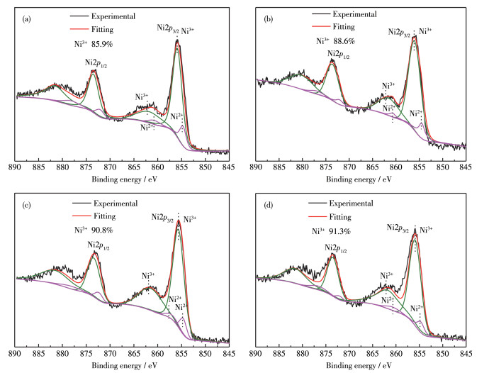
The valence states of transition metal ions were detected by XPS, and the valence states distribution of Ni, Co, and Al are exhibited in Fig. 5 and Fig.S2. As shown in Fig.S2, Ni, Co, Al, O, and C elements were observed in the materials. C1s peak at 284.5 eV corresponded to the absorbed carbon dioxide, which comes from the surface CO32- [2, 15]. The binding energy for the Ni2p and the oxidation states of the corresponding Ni ions were presented in Fig. 5. The Ni2p3/2 peak was fitted with two contributing peaks: one around 854.5 eV, corresponding to the Ni2+, and the other at 855.8 eV, consistent with Ni3+, respectively. For the Ni2p1/2 peak, the peaks with a binding energy of 872.2 and 873.9 eV corresponded to Ni2+ and Ni3+ [22]. Stronger vibration peaks suggested that most of the nickel in the crystal structure was oxidized to Ni3+. The contents of Ni2+ and Ni3+ were semi-quantitative analyzed by fitted to their relative peak area[23]. As expected, the relative content of Ni3+ increased from 85.9% to 91.3% in original samples with extended calcination time. When the sintering time was 12 h, most of Ni2+ was oxidized to Ni3+. With the further prolongation of calcination time, the Ni3+ content remained almost constant, meaning that the degree of Li+/Ni2+ mixing in samples had no significant improvement. This is well consistent with XRD analysis.
Fig. 6 presents the SEM images of the prepared gradient NCA. All particles were spherical, and the diameter of the particle was 6-8 µm. Each secondary particle was composed of an agglomerate of primary particles. With the increase of sintering time, the secondary particles were more compact and rarely contained spaces between grains. In another word, the powders had a higher tap density. The tap densities of GNCA-6, GNCA-9, GNCA-12, and GNCA-19 were 1.48, 1.55, 1.73, and 1.84 g·cm-3, respectively. Particles with little gaps could improve the energy density and enhance the cycle performance of the battery. That is due to decreased contact area with electrolytes and reduced attack of HF[24].
Fig. 7a and 7b show charge-discharge curves of cathodes between 2.8 and 4.3 V after the 2nd and 8th. As seen from the graphs, all cathodes did not exhibit a brief voltage platform at around 4.2 V, following kinds of literature[10, 19] reported. The discharge capacity of NCA electrodes increased with increasing calcination time, which was the main redox species with values of 182.5 mAh·g-1 for GNCA-6, 190.0 mAh·g-1 for GNCA-9, 201.3 mAh·g-1 for GNCA-12, and 204.9 mAh·g-1 for GNCA-15 at 0.2C. The GNCA-6, GNCA-9, GNCA-12, and GNCA-15 electrodes delivered a discharge capacity of 142.2, 164.7, 183.1, and 183.2 mAh·g-1 at 1C respectively. GNCA-12 and GNCA-15 had a slightly lower capacity than homogeneous NCA (205.8 mAh·g-1 at 0.2C and 184.2 mAh·g-1 at 1C)[19]. The composition of these samples was the same, but they displayed different charge-discharge performances. As for the NCA cathode, Ni2+ ions occupied in Li+ inter-slabs (cation mixing) could lead to a smaller Li2O interlayer distance, which impedes Li+ diffusivity[25-27]. The chemical composition of samples was near to LiNi0.80Co0.15Al0.05O2, but the composition charge in particles was very different, especially for Ni and Al contents in the core and surface. For concentration-gradient samples, the core had a higher cation mixing than the homogeneous NCA due to a Ni-rich composition. In addition, an Al-rich surface layer might have a high impedance of electrodes because of the electrochemical inactivity of Al. In comparison with concentration-gradient cathode materials, GNCA-6 and GNCA-9 had a higher Ni content in the core and Al in the out-layer, leading to a low Li+ diffusion rate and high impedance upon cycling. Therefore, GNCA-6 and GNCA-9 delivered much lower capacities than GNCA-12 and GNCA-15. GNCA-6 material displayed too low capacity to provide the required energy density for EV batteries. The property of GNCA-6 was not studied. Similarly, GNCA-15 showed a better rate performance than other concentration-gradient materials. In Fig.S3b, GNCA-15 displayed a discharge capacity of 129.2 mAh·g-1 at 10C, in comparison with 122.4 mAh·g-1 for GNCA-12 and 92.5 mAh·g-1 for GNCA-9.
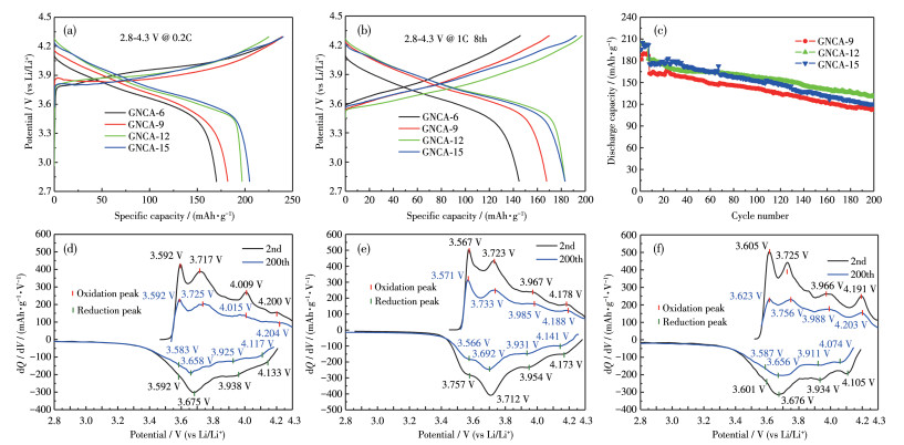
The comparison of cycle performance for GNCA-9, GNCA-12, and GNCA-15 is shown in Fig. 7c. As shown in Fig. 7b and Fig.S3a, GNCA-9, GNCA-12, and GNCA-15 delivered a capacity retention of 68.2%, 71.6%, and 65.7% after 200 cycles, whereas the homogeneous one faded quickly to 54.6%[17-19]. Noteworthy, the markedly enhanced cyclic performance of NCA can be attributed to the improved stability of the cathode-electrolyte interphase benefited from the concentration-gradient layer. Then phase transformation would be restrained during the cycling process[8, 19]. The Ni-deficient composition layer can efficiently block electrolyte attacks of the Ni-rich composition. As a result, concentration-gradient NCA showed better cycle stability than homogeneous ones. Secondary particles of GNCA-9 composed of primary particles had many spaces and were increased attack of electrolyte because of increased contact area with electrolyte. In comparison, the surface composition of GNCA-12 (LiNi0.732Co0.153Al0.115O2) with the one of GNCA-15 (LiNi0.759Co0.152Al0.089O2), a more Al-deficient and Ni-rich layer could reduce cycling stability. The rate capability of cathodes which was denoted by the normalized discharge capacity versus discharge rate is exhibited in Fig.S3c. GNCA-12 and GNCA-15 presented commendable rate capabilities. An appropriate concentration gradient structure leads to an excellent dynamic process.
Moreover, the corresponding differential capacity vs voltage profiles derivative (dQ/dV) curves are shown in Fig. 7d-7f. In the voltage platform, little voltage fluctuations of LIB will cause a great capacity, which shows a peak in the dQ/dV curve, corresponding to an electrochemical reaction[8]. So, dQ/dV curves are used to analyze the phase transitions and polarization degree in the gradient electrodes. The dQ/dV curves showed a series of phase transitions. It was obvious that the dQ/dV curve of the Li/GNCA-9 cell displayed four distinct redox peaks: three significant oxidation peaks at 3.592, 3.717, and 4.009 V and a weak peak at 4.200 V during charging, corresponding to multiphase transitions of hexagonal 1 (H1) to monoclinic M (H1/M), subsequently to hexagonal 2 (H2) and hexagonal 3 (H3); the corresponding reduction peaks were present at 3.592, 3.675, 3.938, and 4.133 V. The four distinct redox peaks characteristic of Li/GNCA-12 and Li/ GNCA-15 cells are shown in Fig. 7d-7f. However, for the NCA materials with Ni atomic fraction at least 0.8, the intensity of the H2-H3 redox peak at around 4.18 V was not observed, suggesting that the cathode retained a substantial of the H2 phase even after being fully charged to 4.3 V[19, 23]. This was consistent with the results of charge-discharge curves (Fig. 7a and 7b), which did not exhibit a brief voltage platform at around 4.2 V. The oxidation peak intensity at around 4.2 V in dQ/dV curves could be used to judge the degree of H2 ⇌ H3 phase transformations, which correlates closely with the unit cell volume contraction (H2 → H3) and expansion (H2 ← H3)[10-11]. During charge-discharging, the volume charge of the unit cell would lead to an accumulation of anisotropic lattice strain, and finally cause a micro-crack on the electrode surface, resulting in the collapse of the secondary particle. As the cycling proceeded, more micro-cracks developed an active material, and then the electrolyte easily infiltrated into the core of the particle, leading to a capacity fading and polarization increasing of the cell[10-11]. The Ni content in the cathode material is related to the degree of the H2 ⇌ H3 phase. Generally, the intensity of oxidation peak at around 4.2 V increases as the Ni content on the surface of NCA increases[11]. However, the extent of the detrimental phase transition was substantially suppressed for the GNCA-9 and GNCA-12 cathode compared to GNCA-15, which was due to lower Ni content in the out-layer of GNCA-12 and GNCA-9. As the cycling proceeded, the oxidation peaks shifted to high voltage, while the reduction peaks moved to low voltage after 200 cycles. It suggested that the electrodes generated polarization upon cycling, demonstrating that electrochemical performance was degraded[27]. To further compare the shift values of the redox peak potential of different cells, the voltage difference of Li/GNCA-9, Li/GNCA-12, and Li/GNCA-15 is listed in Table S2. Li/GNCA-12 with the smallest voltage difference exhibited weak polarization and good reversibility. The dQ/dV curves result in evidence that GNCA-12 has excellent structural stability and capacity retention.
Amounts of cracks generate on the surface of particles, which finally make the structure collapse and result in a high impedance[11-12]. Therefore, EIS for gradient cathode electrodes was investigated to discuss the reason for the upgrade of the cycling performance of the NCA electrodes. In Fig. 8, the Rct values of GNCA-9, GNCA-12, and GNCA-15 based electrodes at the first cycle were 54, 52, and 50 Ω, and increased to 298, 193, and 255 Ω after 200 cycles. The Rct differences of GNCA-9, GNCA-12, and GNCA-15 were 244, 141, and 205 Ω, respectively. It demonstrates that GNCA-12 shows a promoted electrochemical performance.
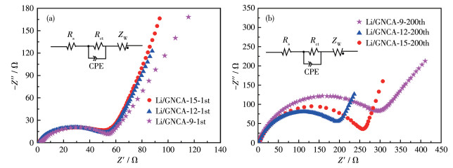
Inset: equivalent circuit diagrams, where Rs is system resistance, CPE is constant phase element, Rct is charge transfer resistance, ZW is Warburg impedance
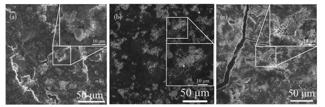
Fig. 9 shows that cracks and loose aggregates of collapsed secondary particles were concentrated on the white color area of the electrode surface. The electrode surfaces of GNCA-9 and GNCA-15 were seriously destructed due to numerous cracks and collapsed secondary particles, while the electrode surface of GNCA-12 remained complete with no obvious cracks observed. The result was according to the dQ/dV curve results. This might be the combination of microtopography and a well-designed Ni-deficient composition layer of GNCA-12. For GNCA-9, the electrolyte easily infiltrated into the spaces of particles and caused the formation of cracks. In comparison to GNCA-15, GNCA-12 with a well-designed Ni-deficient composition layer could significantly reduce the volume stress, which restrained electrolyte attacks of the Ni-rich core and prevented the formation and propagation of micro-cracks at the particle surface. The results show that a well-concentration-gradient NCA can restrain structural degradation and presents better cycling stability.
The concentration-gradient NCA materials have been successfully prepared via co-precipitation by adjusting the Al solution at three flow rates. The EPMA on the cross-section of samples analysis reveals that this precursor had a core-shell structure, and the cathode materials sintered for different calcination times showed different concentration gradient distributions of Ni, Co, and Al. The NCA sintered for 12 h had a full well-designed concentration-gradient structure: The atomic fraction of Ni decreased (0.855 to 0.732) from the core to particle surface, while Al content increased steadily from 0.003 to 0.115 and Co content firstly increased and then decreased to 0.153. This full gradient material displayed a capacity of 201.3 mAh·g-1 at 0.2C and also presented improved capacity retention of 71.6% at 1C after 200 cycles. This NCA had a low cation mixing and efficiently blocks electrolyte attacks of the Ni-rich composition, as well as reduced anisotropic volume variations caused by the H2 ⇌ H3 phase transformation. The composition charge of NCA can be designed accurately by the calcination process, which is stable and controllable in comparison to the co-precipitation process. This is helpful to synthesize NCA materials with nearly the same concentration gradient variation particles and make them commercially viable.
Supporting information is available at
Hwang S, Chang W Y, Kim S M, Su D, Kim D H, Lee J Y, Chung K Y, Stach E A. Investigation of changes in the surface structure of LixNi0.8Co0.15Al0.05O2 cathode materials induced by the initial charge[J]. Chem. Mater., 2014, 26(2): 1084-1092. doi: 10.1021/cm403332s
Li Y J, Wang S L, Chen Y X, Lei T X, Deng S Y, Zhu J, Zhang J P, Guo J. Achieving superior electrochemical performances on LiNi0.8Co0.15Al0.05O2 cathode materials by cadmium oxide modification[J]. Mater. Chem. Phys., 2020, 240: 1220299.
Mohammad M L, Hossein M M, Rahim E. Y2O3-decorated LiNi0.8Co0.15Al0.05O2 cathode material with improved electrochemical performance for lithium-ion batteries[J]. J. Electroanal. Chem., 2019, 848: 113326. doi: 10.1016/j.jelechem.2019.113326
苏岳锋, 张其雨, 陈来, 包丽颖, 卢赟, 陈实, 吴锋. ZrO2包覆高镍LiNi0.8Co0.1Mn0.1O2正极材料提高其循环稳定性的作用机理[J]. 物理化学学报, 2021,37,(3): 110-117. SU Y F, ZHANG Q Y, CHEN L, BAO L Y, LU Y, CHEN S, WU F. Effects of ZrO2 coating on Ni-rich LiNi0.8Co0.1Mn0.1O2 cathodes with enhanced cycle stabilities[J]. Acta Phys.-Chim. Sin., 2021, 37(3): 110-117.
Wu G, Zhou Y K. TiP2O7-coated LiNi0.8Co0.15Al0.05O2 cathode materials with improved thermal stability and superior cycle life[J]. J. Energy Chem., 2019, 28: 151-159. doi: 10.1016/j.jechem.2018.01.018
Kim U H, Park N Y, Park G T, Kim H, Yoon C S, Sun Y K. High-energy W-doped Li[Ni0.95Co0.04Al0.01]O2 cathodes for next-generation electric vehicles[J]. Energy Storage Mater., 2020, 33: 399-407. doi: 10.1016/j.ensm.2020.08.013
Wan D Y, Fan Z Y, Dong Y X, Baasanjav E, Jun H B, Jin B, Jin E M, Jeong S M. Effect of metal (Mn, Ti) doping on NCA cathode materials for lithium ion batteries[J]. J. Nanomater., 2018, 2018: 1-9.
王伟东, 仇卫华, 丁倩倩. 锂离子电池三元材料: 工艺技术及生产应用. 北京: 化学工业出版社, 2015: 68-90, 180-187WANG W D, QIU W H, DING Q Q. Nickel cobalt manganese based cathode materials for Li-ion batteries technology production and application. Beijing: Chemical Industry Press, 2015: 68-90, 180-187
胡国荣, 黄金龙, 杜柯, 曹雁冰, 彭忠东. 高容量梯度锂离子电池正极材料Li[Ni0.85Co0.08Mn0.07]O2的制备[J]. 无机化学学报, 2019,35,(7): 1139-1147. HU G R, HUANG J L, DU K, CAO Y B, PENG Z D. Synthesis of high capacity gradient cathode material Li[Ni0.85Co0.08Mn0.07]O2 for lithium ion battery[J]. Chinese J. Inorg. Chem., 2019, 35(7): 1139-1147.
Duan J G, Peng D, Wang D, Li X, Xiao Z W, Zhang Y J, Hu G R. A facile structure design of LiNi0.90Co0.07Al0.03O2 as advanced cathode materials for lithium ion batteries via carbonation decomposition of NaAl(OH)4 solution[J]. J. Alloy. Compd., 2017, 739: 335-344.
Sun Y K, Kim D H, Jung H G, Myung S T, Amine K. A facile structure design concentration-gradient Li[Ni0.67Co0.15Mn0.18]O2 cathode material for lithium-ion batteries[J]. Electrochim. Acta, 2010, 55: 8621-8627. doi: 10.1016/j.electacta.2010.07.074
Yoo G W, Jang B, Son J T. Novel design of core shell structure by NCA modification on NCM cathode material to enhance capacity and cycle life for lithium secondary battery[J]. Ceram. Int., 2015, 41: 1913-1916. doi: 10.1016/j.ceramint.2014.09.077
Park K J, Choi M J, Maglia F, Kim S J, Kim K H, Yoon C S, Sun Y K. High-capacity concentration gradient Li[Ni0.865Co0.120Al0.015]O2 cathode for lithium-ion batteries[J]. Adv. Energy Mater., 2018, 9(8): 1703612.
Hua W B, Schwarz B, Azmi R, Müllers M, Darma M, Knapp M, Senyshyn A, Missyul A, Simonelli L, Binder J R, Indris S, Ehrenberg H. Lithium-ion (de) intercalation mechanism in core-shell layered Li(Ni, Co, Mn)O2 cathode materials[J]. Nano Energy, 2020, 78(3): 105231.
Kasnatscheew J, Evertz M, Streipert B, Wagner R, Klöpsch R K, Vortmann B, Hahn H, Nowak S, Amereller M, Gentschev A C, Lamp P, Winter M. The truth about the 1st cycle coulombic efficiency of LiNi1/3Co1/3Mn1/3O2 (NCM) cathodes[J]. Phys. Chem. Chem. Phys., 2016, 18(5): 3956-3965. doi: 10.1039/C5CP07718D
Venkatraman S, Choi J, Manthiram A. Factors influencing the chemical lithium extraction rate from layered LiNi1-y-zCoyMnzO2 cathodes[J]. Electrochem. Commun., 2004, 6(8): 832-837. doi: 10.1016/j.elecom.2004.06.004
Duan J G, Hu G R, Cao Y B, Tan C P, Wu C, Du K, Peng Z D. Enhanced electrochemical performance and storage property of LiNi0.815Co0.15Al0.035O2 via Al gradient doping[J]. J. Power Sources, 2016, 326: 322-330. doi: 10.1016/j.jpowsour.2016.07.008
Liang M, Sun Y M, Song D W, Shi X X, Han Y, Zhang H Z, Zhang L Q. Superior electrochemical performance of quasi-concentration-gradient LiNi0.8Co0.15Al0.05O2 cathode material synthesized with multi-shell precursor and new aluminum source[J]. Electrochim. Acta, 2019, 300: 426-436. doi: 10.1016/j.electacta.2019.01.125
郭宇, 黄玲, 肖方明, 王英, 唐仁衡. 高镍系Li[(Ni0.88Co0.12)0.90(Ni0.80Co0.15Al0.05)0.10]O2正极材料的制备研究[J]. 电源技术, 2020,44,(1): 13-16. GUO Y, HUANG L, XIAO F M, WANG Y, TANG R H. Preparation of high nickel system Li[(Ni0.88Co0.12)0.90(Ni0.80Co0.15Al0.05)0.10]O2 cathode material[J]. Chinese Journal of Power Sources, 2020, 44(1): 13-16.
广东省稀有金属研究所. 梯度含量正极材料及其制备方法: CN202010548402.0. 2020-10-13.Institute of Rare Metals, Guangdong Academy of Sciences. Gradient content cathode material and preparation method: CN202010548402.0. 2020-10-13.
Huang L, Wang Y, Zhou Q, Xiao F M, Guo Y, Tang R H, Li W C. A facile structure design of concentration-gradient LiNi0.80Co0.15Al0.05O2 cathode material for lithium-ion batteries via controlling the flow rate of Al solution[J]. J. Alloy. Compd., 2021, 857(15): 157528.
Hiroaki K, Masanori Y, Tatsumi K. The effect of thermal stability for high-Ni-content layer-structured cathode materials, LiNi0.8Mn0.1-xCo0.1MoxO2 (x=0, 0.02, 0.04)[J]. J. Power Sources, 2013, 244(15): 23-28.
Lei Y K, Ai J J, Yang S A, Jiang H Y, Lai C Y, Xu Q J. Effect of flower-like Ni(OH)2 precursors on Li+/Ni2+ cation mixing and electrochemical performance of nickel-rich layered cathode[J]. J. Alloy. Compd., 2019, 797: 421-431. doi: 10.1016/j.jallcom.2019.05.065
Noh H J, Youn S, Yoon C S, Sun Y K. Comparison of the structural and electrochemical properties of layered Li[NixCoyMnz]O2 (x=1/4, 1/3, 0.5, 0.6, 0.7, 0.8 and 0.85) cathode material for lithium-ion batteries[J]. J. Power Sources, 2013, 233(1): 121-130.
Lee K K, Kim K B. Electrochemical and structural characterization of LiNi1-yCoyO2 (0≤y≤0.2) positive electrodes during initial cycling[J]. J. Electrochem. Soc., 2000, 147(5): 1709-1717. doi: 10.1149/1.1393422
Yoshizawa H, Ohzuku T. An application of cobalt nickel manganese oxide to high-power and high-energy density lithium-ion batteries[J]. J. Power Sources, 2007, 174(2): 813-817. doi: 10.1016/j.jpowsour.2007.06.153
Wu F, Li N, Su Y F, Shou H F, Bao L Y, Yang W, Zhang L J, An R, Chen S. Spinel/layered heterostructured cathode material for high-capacity and high-rate Li-ion batteries[J]. Adv. Mater., 2013, 25(27): 3722-3727. doi: 10.1002/adma.201300598

Figure 1 (a) PSA data of the precursors, (b) EPMA point scans for core-shell precursor (Inset: cross-section SEM image), and SEM mages for (c) core precursor and (d) core-shell precursor

Figure 3 EPMA point scanning of (a) GNCA-6, (b) GNCA-9, (c) GNCA-12, and (d) GNCA-15
Inset: corresponding cross-section SEM images

Figure 4 XRD patterns of (a) GNCA-6, (b) GNCA-9, (c) GNCA-12, and (d) GNCA-15; Corresponding XRD patterns of (e) (006)/(012) and (f) (018)/(110) peaks

Figure 7 (a, b) Charge-discharge curves and (c) cyclic performance of the samples; dQ/dV curves of charge-discharge curves at 2nd and 200th for (d) GNCA-9, (e) GNCA-12, and (f) GNCA-15

Figure 8 Nyquist plots of bare Li concentration-gradient materials: (a) 1st cycle; (b) 200th cycle
Inset: equivalent circuit diagrams, where Rs is system resistance, CPE is constant phase element, Rct is charge transfer resistance, ZW is Warburg impedance

 扫一扫看文章

扫一扫关注我们
 下载:
下载:
 下载:
下载:


