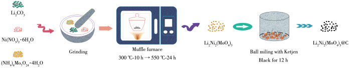
Figure 1.
Synthesis schematic diagram of Li2Ni2(MoO4)3@C

Lithium-ion batteries (LIBs), one of the most promising energy storage devices, have been extensively used in many fields, such as electronic vehicles and portable devices[1-2]. At present, graphite is mainly used to the commercial anode material for LIBs with a theoretical capacity of 372 mAh·g-1[3]. With the growing demand for various electronic products, new anode materials with admirable properties that contain high capacity and safety performance are required. Among those alternative graphite materials, Mo-based bimetallic oxides (such as Li2MoO4, FeMoO4, Bi2MoO6, and Cr3Mo2O12), as conversion reaction materials, benefiting from the high capacity delivered due to the multielectron transfer during the lithiation/delithiation pro-cess, have been investigated intensively for lithium-ion battery anodes[4-7]. However, the inherent low electrical conductivity of these materials and the structural instability during the reaction process shackle its practical application.
In the past ten or twenty years, Na-super-ionicconductor (NASICON) framework type lithiated bimetallic oxides, such as Li3Fe(MoO4)3, Li2Co2(MoO4)3, Li2FeSiO4, and Li3V(MoO4)3, have been systematically studied as cathode materials, and it has been found that they have excellent electrochemical properties, which are mainly attributed to their three dimensional framework structure with the coordination between different metals and many lithium ion channels during the charge/discharge process[8-9]. In recent years, many studies have proved that the above cathode materials can be applied as excellent anode materials for LIBs[10-11]. For example, Chen et al. prepared a pure Li3Fe(MoO4)3 with micro-nanoporous structure. Electrochemical test showed that the charge capacity was 622 mAh·g-1 after 450 cycles at a current density of 100 mA·g-1 [10]. In 2004, Quaternary lithium nickel molybdenum oxide, Li2Ni2(MoO4)3, was first reported by Prabaharan as a novel cathode material for rechargeable lithium batteries[12]. The reversible intercalation capacity of Li2Ni2(MoO4)3 was 115 mAh·g-1 in the voltage range of 1.5 to 4.9 V. When Ni2+ and Mo6+ are completely reduced to the corresponding metallic elementals, it can be expected that Li2Ni2(MoO4)3 has a high theoretical specific capacity (965 mAh·g-1). As far as we know, there is no research on Li2Ni2(MoO4)3 as anode material for LIBs. Therefore, it is of great significance to develop high performance anode materials based on Li2Ni2(MoO4)3.
Herein, Li2Ni2(MoO4)3@C composite was successfully synthesized via a simple method using the conventional solid state process combined with ball milling technique. When first applied as anode material for LIBs, it showed high delithium capacity with high initial coulombic efficiency (85%). Meanwhile, Li 2Ni2 (MoO4)3@C electrode also showed excellent cycling and rate performance, which is attributed to that the addition of carbon not only improves the electrical conductivity of the material, but also as a buffer medium alleviates the large volume changes in the process of charge and discharge. In addition, the lithium storage mechanism of Li2Ni2(MoO4)3@C was preliminarily explored by cyclic voltammetry (CV).
First, Li2CO3, Ni(NO3)2∙6H2O, and (NH4)6Mo7O24∙4H2O were adequately ground in an agate mortar for 30 min with a molar ratio of nLi∶nNi∶nMo being 2∶2∶3, and the mixture was heated in air at 300 ℃ for 10 h and then at 550 ℃ for 24 h to obtain a pure phase of Li2 Ni 2(MoO4) 3. Next, Li2Ni 2(MoO4)3@C was synthesized by planetary ball milling (QM-3SP04, Nanjing NanDa Instrument Plant, China) at 400 r·min-1 for 12 h. The mass ratio of Li2Ni2(MoO4)3 to Ketjen Black (ECP 600JD, Lion Corporation) was 8∶2. The mass ratio of grinding balls to the material was set as 40∶1. For comparison, pure Li2Ni 2(MoO4) 3 without added Ketjen Black was also ball milled under the same condition. The synthesis schematic diagram of Li2Ni2(MoO4)3 and Li2Ni2(MoO4)3@C is shown in Fig.1.
The crystalline structure of the materials was investigated using X-ray diffractometer (XRD, Ultima Ⅳ) with Cu Kα radiation (λ =0.154 nm) at 40 kV and40 mA in a scanning range of 10°~80° (2θ). The surface morphologies were observed by scanning electron microscopy (SEM, JSM-7500F) working at 10 kV and transmission electron microscopy (TEM, JEM-2100F) operated at 200 kV. Thermogravimetric analysis (TG,DTG-60H) was carried out under air atmosphere with a temperature ramp of 10 ℃ ·min-1. The surface valence states of the samples were researched by X-ray photoelectron spectroscopy (XPS, PHI 5000 Versa Probe) with Al Kα radiation (λ=0.835 nm).
The electrochemical performance of Li2Ni2(MoO4)3 and Li2Ni 2(MoO4)3@C was evaluated by a 2016 type coin cell assembled in a MBRAUN glove box filled high-purity argon gas. The working electrode consisted of Li2Ni2(MoO 4)3 (or Li2Ni2(MoO4)3@C), carbon powder (Super p) and adhesive (polyvinylidene fluoride) (mass ratio of 8∶1∶1). Li foil and Celgard-2400 membrane were served as counter electrode and separators, respectively. The electrolyte was constituted by 1.0 mol·L-1 LiPF6 dissolved in ethyl methyl carbonate (EMC), dimethyl carbonate (DMC), and ethylene carbonate (EC) (volume ratio: 1∶1∶1). The CV and electrochemical impedance spectroscopy (EIS) of the as prepared samples were performed on an electrochemical workstation (CHI660e, Chenhua Instrument Co., Ltd., Shanghai, China). Constant current discharge charge tests were completed at a NEWAR CT3008 battery system.
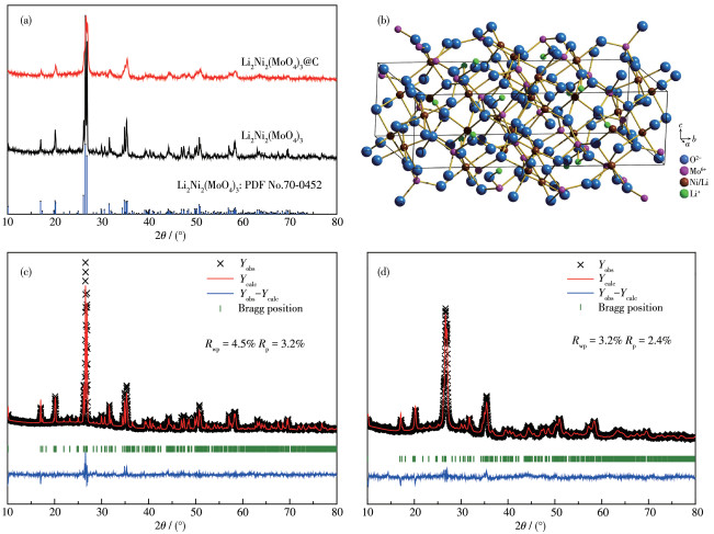
The XRD patterns of Li2Ni2(MoO4) 3 and Li2Ni2 (MoO4)3@C are displayed in Fig. 2a. For comparison, Fig. S1 (Supporting information) illustrates the XRD pattern of ball-milled Li2 Ni2(MoO4)3. All the peak positions are well indexed as PDF card (PDF No.70-0452, an orthorhombic structure with space group Pmcn), indicating that the samples form a well single phase crystalline structure. In addition, the characteristic diffraction peaks of carbon are not found, demonstrating it exists as an amorphous state in Li2Ni2(MoO4)3@C composite after ball milling[13]. In contrast to pristine Li2Ni2 (MoO4)3, the broadening of some diffraction peaks observed in Li2Ni2(MoO4)3@C can be attributed to particle refinement after ball milling[14], which is shown in the SEM measuring results below. Fig. 2b presents the crystal structure of Li2Ni2(MoO4)3 as determined by the Diamond software, where the figure exhibits a three-dimensional framework. What matters is that the open frame structure may allow Li+ to move into and out of the structure easily[5]. In order to obtain accurate structural information, Rietveld refinements of XRD profiles of the as-synthesized samples were performed by the GSAS software. As shown in Fig.2c and 2d, the calculated results are in good agreement with the experimental XRD patterns. Rp and Rwp are collectively referred to as reliability factors, representing profile factor and weighted profile factor, respectively. The Rietveld refinements are credible only if Rp and Rwp values are both under 15%[15]. For Li2Ni2(MoO4)3, the refinement terminates with Rp=3.2% and Rwp=4.5%. The corresponding lattice parameters were calculated to be a= 1.040 69(8) nm, b=1.749 83(1) nm, c=0.507 89(4) nm, and V=0.924 89(2) nm3. These values are very close to standard data (a=1.042 nm, b=1.752 nm, c=0.507 nm), which also corresponds with the conclusion drawn by the above XRD. The detailed structural parameters of Li2Ni2(MoO4)3 and Li2Ni2(MoO4)3@C acquired from the refinement results are summarized in Table 1.
 下载:
导出CSV
下载:
导出CSV
| Sample | Space group | a/nm | b/nm | c/nm | α=β=γ/(°) | V/nm3 |
| Standard | Pmcn | 1.042 | 1.752 | 0.507 | 90 | 0.926 83 |
| Li2Ni2(MoO4)3 | Pmcn | 1.040 69(8) | 1.749 83(1) | 0.507 89(4) | 90 | 0.924 89(2) |
| Li2Ni2(MoO4)3@C | Pmcn | 1.047 95(3) | 1.762 31(5) | 0.511 22(1) | 90 | 0.930 13(5) |
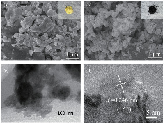
The morphology of Li2Ni2(MoO4)3 prepared by solid state synthesis was revealed by SEM, as shown in Fig. 3a. It is obvious that the sample shows irregular sintered block shape. When Li2Ni2(MoO4)3 was milled with Ketjen Black (Fig. 3b), it displayed irregular agglomeration. It can be seen that the particle sizes of most of Li2Ni2(MoO4)3@C were smaller than that of pure Li2Ni2(MoO4)3 after ball milling. The average particle size was roughly calculated by Image-Pro software from SEM images. The sizes of Li2Ni2(MoO4)3 and Li2Ni2 (MoO4)3@C were ~0.31 and ~0.15 μm, respectively. Further, among various strategies to improve electrochemical behavior, reducing the particle size is an effective method to shorten the diffusion path of ions for LIBs[16]. Digital photographs of Li2Ni2(MoO4)3 and Li2Ni2(MoO4)3@C are displayed in the upper right corners of Fig. 3a and 3b. Li2Ni2(MoO4)3@C powder was black in sharp contrast with the yellow Li2Ni2(MoO4)3 powder, which demonstrates that Li2Ni2(MoO4)3 particles have become a composite with carbon. Fig.3c presents the TEM image of Li2Ni2(MoO4)3@C, where the size of the particles was about 145 nm. The particle size is basically consistent with the SEM measurement result. High-resolution TEM (HRTEM) image (Fig.3d) exhibited a 0.246 nm lattice spacing corresponding to the (161) plane of Li2Ni2(MoO4)3. The perfect lattice fringe indicates the excellent crystal structure of Li2Ni2 (MoO4)3, which is essential for the high-performance anodes of LIBs.
Inset in (a) and (b): powder sample images
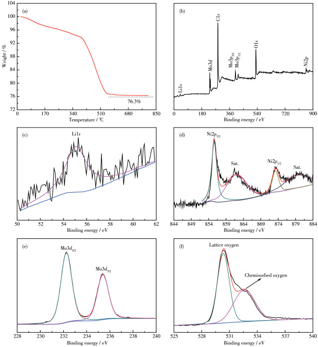
The TG curve of Li2Ni 2 (MoO4)3@C composite under air atmosphere is shown in Fig. 4a. The weight percentage of Li2Ni2(MoO4)3 in the composite was 76.3% at 800 ℃, which is roughly the same as the feed ratio before ball -milling. The electronic state of different elements of Li 2Ni2(MoO4)3@C was verified by XPS, as presented in Fig. 4b~4f. The survey spectrum (Fig.4b) exhibits the existence of Li, Ni, Mo, and O, as well as C from the composite material and the reference electrode. The binding energy observed near 56 eV is in line with the Li1s XPS spectrum (Fig.4c)[12]. As shown in Fig. 4d, the two peaks located at 856.1 and 873.4 eV can be ascribed to Ni2p3/2 and Ni2p1/2, representative of the presence of Ni2+[17]. And there are two satellite peaks with binding energies at 878.8 and 860.9 eV (Fig. 4d). The binding energies of two peaks existed at 232.4 and 235.5 eV are assigned to Mo3d5/2 and Mo3d3/2, respectively, which corresponds to the characteristic of Mo6+ as depicted in Fig.4e[18]. The O1s XPS spectrum for Li2Ni2(MoO4)3@C shows two peaks with binding energies at 530.4 and 532.5 eV, which is attributed to the lattice oxygen and chemisorbed oxygen, respectively (Fig.4f)[8].
The lithium intercalation/de intercalation behavior of pure Li2Ni2(MoO4)3 and Li2Ni2(MoO4)3@C composite was studied by CV and galvanostatic chargedischarge cycling. Fig. 5a shows the first three CV curves of Li2Ni2(MoO4)3@C electrode for LIBs in the voltage range of 0.02~3.0 V (vs Li+/Li) at the scan rate of 0.1 mV·s-1, which is similar to that of NiMoO4 anodes[19]. The initial cathodic scan displays three reduction peaks at 1.46, 0.70, and 0.17 V. The peak at 1. 46 V involves an irreversible transition, possibly due to the insertion of Li+ into the Li2Ni2(MoO4)3. This phenomenon also appears in another molybdenum based material[5, 10-11]. The other two peaks correspond to the transformation of Mo6+ to Mo and Ni2+ to Ni, accompanied by the formation of solid electrolyte interface (SEI) film on the electrode surface. When the scanning direction was reversed, the anodic peak at 1.38 V can be related to the oxidation of Mo to Mo4+, while the peak located 1.80 V represents the overlapping peaks of Mo4+ to Mo6+ and Ni to Ni2+ [19]. It can be visibly seen from the second cycle that three reduction peaks appeared (1.50, 0.64, and 0.15 V). Among them, the peaks located at 1.50 and 0.15 V may be attributed to the multi step reduction of Mo6+ to Mo[10]. Another reduction peak at 0.64 V can be related to the reduction of Ni2+ to Ni[20]. Meanwhile, two peaks at 1.38 and 1.80 V are shown in the anodic process, which is basically consistent with the initial anodic scans. During the scanning process, the changes in the redox potential of Ni2+ and Mo6+ are related to the existence of the polyanion (MoO4)2- in the main frame structure[21]. Clearly, the CV curves of Li2Ni2(MoO4)3@C after the first cycle overlap better than that of pure Li2Ni2(MoO4)3(Fig. 5b), indicating that the former has superior reversibility as an anode material. In short, the reaction processes are as follows:
|
|
(1) |
|
|
(2) |
|
|
(3) |
|
|
(4) |
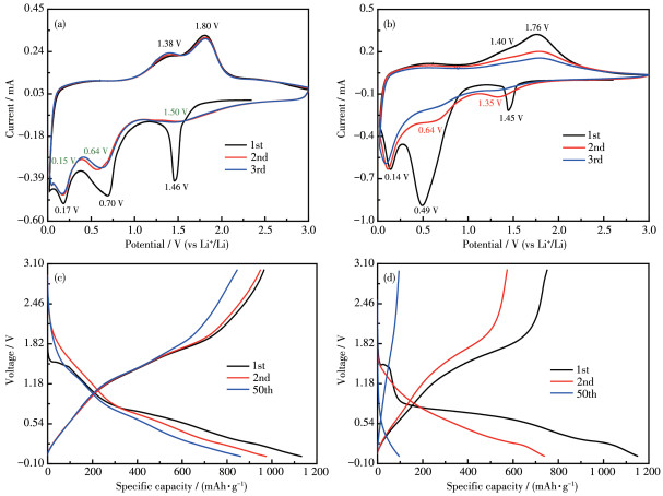
Fig. 5c presents the charge/discharge curves of Li2Ni2(MoO4)3@C electrode for the 1st, 2nd, and 50th cycles at 200 mA·g-1. During the first discharge process, three voltage platforms were recorded, which was also in line with the CV results (Fig.5a). First, a short platform located at 1.5 V (86 mAh·g-1), which corresponded to the intercalation of 2Li+ into Li2Ni2(MoO4)3[21]. When the discharge voltage was below 1 V, the two voltage platforms contribute a capacity sum of 930 mAh·g-1 (21Li+), which is involved in the decomposition of Li2+xNi2(MoO4)3 to produce Ni and Mo as well as the formation of SEI film. It is worth noting that the polarization of Li2Ni2(MoO4)3@C between the discharge platform and the charging platform is smaller than that of Li2Ni2(MoO4)3 (Fig. 5d), indicating that its kinetic characteristics are better than that of Li2Ni2(MoO4)3. The improved kinetics of Li2Ni2(MoO4)3@C can be attributed to the higher electrical conductivity and Li+ ion diffusivity[22-23].
The comparative cycling performance of Li2Ni2(MoO4)3 and Li2Ni2(MoO4)3@C composite electrodes at a current density of 200 mA·g-1 is shown in Fig.6a. For Li2Ni2(MoO4)3@C electrode, the initial discharge and charge capacities were 1 131 and 961 mAh·g-1, respectively, corresponding to the initial columbic efficiency of 85%. It should be noted that such a high coulomb efficiency is very competitive in reported anode materials, which is of great importance for practical applications[11]. Li2Ni2(MoO4)3@C delivered a charge capacity of 845 mAh·g-1 after 50 cycles and exhibited excellent capacity retention (87.5% of the initial capacity). In contrast, pure Li2Ni2(MoO4)3 remained at 95 mAh·g-1 and the capacity retention was only 12.6%. In addition, the cycle properties of ball milled Li2Ni2(MoO4)3 without adding Ketjen Black were also characterized under the same condition. As shown in Fig.S2, the reversible capacity of ball-milled Li2Ni2(MoO4)3 was only 135 mAh·g-1 after 50 discharge-charge cycles. This significantly enhanced electrochemical performance is mainly attributed to the fact that Ketjen Black in Li2Ni2(MoO4)3@C composite protect the electrode from collapse due to volume expansion/contraction during Li+ insertion/extraction process, thus improving the electrode stability[22].
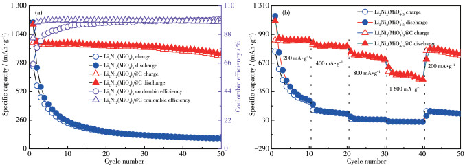
To verify practicality, the rate capabilities of Li2Ni2(MoO4)3 and Li2Ni2(MoO4)3@C electrodes were also studied at different current densities, as shown in Fig. 6b. Li2Ni2(MoO4)3@C electrode showed a superior rate performance with the specific discharge capacity of approximately 936, 876, 760, and 551 mAh·g-1 at 200, 400, 800, and 1 600 mA·g-1, respectively. After 40 cycles, when the current density was restored to 200 mA·g-1, the specific discharge capacity could recover to ~811 mAh·g-1, which is 86% of the first stage capacity. By contrast, Li2Ni2(MoO4)3 only returned to 32% under the same conditions, indicating that Li2Ni2(MoO4)3@C possesses a good structural stability under the large current density changes.
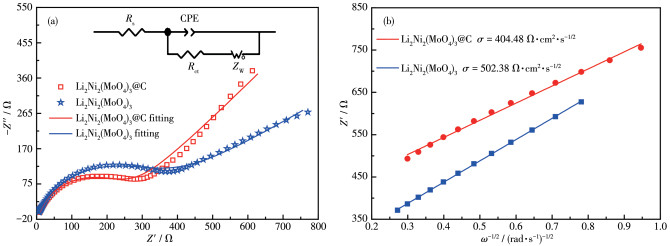
In order to further investigate the reasons for the improved electrochemical properties, comparative alternating current (AC) impedance spectroscopy analyses were performed after the rate performance cycles. There are a semicircle and a sloping line in the Nyquist plot that was fitted using the equivalent circuit acquired by Z-view software (Fig.7a). In the equivalent circuit, Rs, Rct, CPE and ZW stand for ohmic resistance of electrolyte and contact resistance, resistance of charge transfer, double layer capacitance, and Warburg impedance controlled by diffusion, respectively[24]. The diffusion coefficient of lithium ions (DLi) was calculated according to the following equation[25-26]:
|
|
(5) |
Where R, T, A, n, F, c, and σ represent gas constant, absolute temperature, surface area of the anode, number of electrons per molecule during oxidization, Faraday constant, concentration of lithium-ion and Warburg factor, respectively. The σ is relative with Z′:
|
|
(6) |
Fig. 7b presents the linear fitting of Z′ vs ω-1/2, from which the slope σ can be derived. Based on Eq.5, it is possible to calculate DLi of the samples using the σ value. The fitting results of resistance and the values of DLi are tabulated in Table 2. It is obvious that the Rs and Rct for Li2Ni2(MoO4)3@C electrode are smaller than those of pure Li2Ni2(MoO4)3 electrode, demonstrating that Li2Ni2(MoO4)3@C electrode possesses a more stable surface film and a faster charge transfer process. In addition, the DLi values of Li2Ni2(MoO4)3@C and Li2Ni2(MoO4)3 indicate that the electrochemical kinetics for Li2Ni2(MoO4)3@C is easier with Li+ insertion/extraction than Li2Ni2(MoO4)3, which also verifies the enhancement of lithium storage performance of Li2Ni2(MoO4)3@C after compounding with carbon.
下载:
导出CSV
| Sample | Rs/Ω | Rct/Ω | DLi/(cm2·s-1) |
| Li2Ni2(MoO4)3@C | 8.21 | 241.9 | 5.36×10⁻¹³ |
| Li2Ni2(MoO4)3 | 10.21 | 300.2 | 3.48×10⁻¹³ |
In summary, Li2Ni2(MoO4)3@C composite was synthesized using solid-state reaction combined with ball milling and researched as novel anode material for LIBs. In contrast to Li 2Ni2(MoO4)3, Li2Ni2(MoO4)3@C composite exhibited competitive rate performance and cyclic stability. Moreover, Li2Ni2(MoO4)3@C provided a discharge capacity of 861 mAh·g-1 after 50 cycles at 200 mA·g-1 and delivered high initial coulombic efficiency of 85%. The excellent electrochemical performance is due to the reduction of particle size after ball milling, and more importantly, the carbon matrix of Li 2Ni2(MoO4)3@C composite can improve electrode conductivity, buffer massive volume changes, and raise reaction kinetics. All the results highlight that Li2Ni2(MoO4)3@C would become a promising candidate for new anode materials of LIBs.
Lin X T, Qian S S, Yu H X, Yan L, Li P, Wu Y Y, Long N B, Shui M, Shu J. ACS Sustainable Chem. Eng., 2016,4(9):4859-4867 doi: 10.1021/acssuschemeng.6b01137
Zhang Q B, Chen H X, Luo L L, Zhao B T, Luo H, Han X, Wang J W, Wang C M, Yang Y, Zhu T, Liu M L. Energy Environ. Sci., 2018,11:669-681 doi: 10.1039/C8EE00239H
Tian F H, Cheng Y Q, Zhang Y J, Zhao Q Z, Shi Q, Zhang Y, Zhou C, Yang S, Song X P. Mater. Lett., 2021,284:129019 doi: 10.1016/j.matlet.2020.129019
Zhang J Y, Li R L, Chen Q, Zhao G H, Jia J F. Mater. Lett., 2018,233:302-305 doi: 10.1016/j.matlet.2018.09.032
Ju Z C, Zhang E, Zhao Y L, Xing Z, Zhuang Q C, Qiang Y H, Qian Y T. Small, 2015,11(36):4753-4761 doi: 10.1002/smll.201501294
Zhang Y, Zhao G G, Ge P, Wu T J, Li L, Cai P, Liu C, Zou G Q, Hou H S, Ji X B. Inorg. Chem., 2019,58:6410-6421 doi: 10.1021/acs.inorgchem.9b00627
Guo L, Wang Y. J. Mater. Chem. A, 2015,3:15030-15038 doi: 10.1039/C5TA03256C
Prabaharan S R S, Ramesh S, Michael M S, Begam K M. Mater. Chem. Phys., 2004,87:318-326 doi: 10.1016/j.matchemphys.2004.05.041
Mikhailova D, Sarapulova A, Voss A, Thomas A, Oswald S, Gruner W, Trots D M, Bramnik N N, Ehrenberg H. Chem. Mater., 2010,22:3165-3173 doi: 10.1021/cm100213a
Chen S Y, Duan H, Zhou Z Y, Fan Q H, Zhao Y M, Dong Y Z. J. Power Sources, 2020,476:228656 doi: 10.1016/j.jpowsour.2020.228656
Wang J X, Zhang G B, Liu Z M, Li H K, Liu Y, Wang Z X, Li X H, Shih K, Mai L Q. Nano Energy, 2018,44:272-278 doi: 10.1016/j.nanoen.2017.11.079
Prabaharana S R S, Fauzib A, Michael M S, Begam K M. Solid State Ionics, 2004,171:157-165 doi: 10.1016/j.ssi.2004.05.001
Wakayama H, Mizuno J, Fukushima Y, Nagano K, Fukunaga T, Mizutani U. Carbon, 1999,37:947-952 doi: 10.1016/S0008-6223(98)00249-8
Eom J, Cho Y, Kim S, Han D, Sohn D. J. Alloys Compd., 2017,723:456-461 doi: 10.1016/j.jallcom.2017.06.210
Gao H Y, Jiao L F, Peng W X, Liu G, Yang J Q, Zhao Q Q, Qi Z, Si Y C, Wang Y J, Yuan H T. Electrochim. Acta, 2011,56:9961-9967 doi: 10.1016/j.electacta.2011.08.086
Liu P C, Bian K, Zhu K J, Xu Y, Gao Y F, Luo H J, Lu L, Wang J, Liu J S, Tai G. ACS Appl. Mater. Interfaces, 2017,9:17002-17012 doi: 10.1021/acsami.7b01504
Wang L, He Y C, Mu Y L, Liu M J, Chen Y F, Zhao Y, Lai X, Bi J, Gao D J. Front. Chem., 2018,6:492 doi: 10.3389/fchem.2018.00492
Liang H Y, Lin J H, Jia H N, Chen S L, Qi J L, Cao J, Lin T S, Fei W D, Feng J C. J. Power Sources, 2018,378:248-254 doi: 10.1016/j.jpowsour.2017.12.046
Oh S H, Kim J K, Kang Y C, Cho J S. Nanoscale, 2018,10:18734-18741 doi: 10.1039/C8NR06727A
Jiang G X, Li L, Xie Z J, Gao B Q. Ceram. Int., 2019, 45:18462-18470 doi: 10.1016/j.ceramint.2019.06.064
Prabaharan S R S, Michael M S, Ramesh S, Begam K M. J. Electroanal. Chem., 2004,570:107-112 doi: 10.1016/j.jelechem.2004.03.022
Tan Z, Sun Z H, Wang H H, Guo Q, Su D S. J. Mater. Chem. A, 2013, 1:9462 doi: 10.1039/c3ta10524e
Li B, Xiao Z J, Zai J T, Chen M, Wang H H, Liu X J, Li G, Qian X F. Mater. Today Energy, 2017,5:299-304 doi: 10.1016/j.mtener.2017.07.006
Wang F, Fang Z W, Zhang Y. J. Electroanal. Chem., 2016,775:110-115 doi: 10.1016/j.jelechem.2016.05.041
Liu H, Li C, Cao Q, Wu Y P, Holze R. J. Solid State Electrochem., 2008,12:1017-1020 doi: 10.1007/s10008-007-0480-4
Amin K, Meng Q H, Ahmad A, Cheng M, Zhang M, Mao L J, Lu K, Wei Z X. Adv. Mater., 2018,30:1703868 doi: 10.1002/adma.201703868

Figure 2 (a) XRD patterns of Li2Ni2(MoO4)3 and Li2Ni2(MoO4)3@C; (b) Crystal structure of Li2Ni2(MoO4)3; Rietveld refinement results of XRD patterns for (c) Li2Ni2(MoO4)3 and (d) Li2Ni2(MoO4)3@C

Figure 3 SEM images of (a) Li2Ni2(MoO4)3 and (b) Li2Ni2(MoO4)3@C; (c) TEM image and (d) HRTEM image of Li2Ni2(MoO4)3@C
Inset in (a) and (b): powder sample images

Figure 4 (a) TG curve of Li2Ni2(MoO4)3@C in an air atmosphere; XPS spectra of Li2Ni2(MoO4)3@C: (b) survey spectrum, (c) Li1s, (d) Ni2p, (e) Mo3d, and (f) O1s

Figure 5 CV profiles of (a) Li2Ni2(MoO4)3@C and (b) Li2Ni2(MoO4)3 at scan rate of 0.1 mV·s-1; Discharge/charge curves of (c) Li2Ni2(MoO4)3@C and (d) Li2Ni2(MoO4)3 at 200 mA·g-1

Figure 6 (a) Cycling performance at 200 mA·g-1 and (b) rate performance of as-prepared samples

Figure 7 (a) EIS spectra of Li2Ni2(MoO4)3 and Li2Ni2(MoO4)3@C (Inset: simulated equivalent circuit); (b) Relationship between Z′ and the square root of frequency (ω-1/2) in the low frequency region
Table 1. XRD refinement results of as-prepared samples
| Sample | Space group | a/nm | b/nm | c/nm | α=β=γ/(°) | V/nm3 |
| Standard | Pmcn | 1.042 | 1.752 | 0.507 | 90 | 0.926 83 |
| Li2Ni2(MoO4)3 | Pmcn | 1.040 69(8) | 1.749 83(1) | 0.507 89(4) | 90 | 0.924 89(2) |
| Li2Ni2(MoO4)3@C | Pmcn | 1.047 95(3) | 1.762 31(5) | 0.511 22(1) | 90 | 0.930 13(5) |
 下载: 导出CSV
Table 2. Fitted impedance parameters of Li2Ni2(MoO4)3@C and Li2Ni2(MoO4)3
| Sample | Rs/Ω | Rct/Ω | DLi/(cm2·s-1) |
| Li2Ni2(MoO4)3@C | 8.21 | 241.9 | 5.36×10⁻¹³ |
| Li2Ni2(MoO4)3 | 10.21 | 300.2 | 3.48×10⁻¹³ |
下载: 导出CSV

 扫一扫看文章

扫一扫关注我们
