Figure 1.
Abridged general view of the alkaline Zn-air battery

Oxygen reduction reaction (ORR) as the cathodic process is one of the most critical factors in the performance of some electrochemical devices like fuel cells and metal-air batteries. Therefore, it is very significant to develop highly efficient ORR electrocatalysts for the normal operation of the devices[1-3]. Although platinum and platinum- based materials have long been considered as the best catalysts for ORR activity, their commercial application to fuel cells and metal-air batteries on a large scale is greatly limited due to the high cost and scarcity of platinum[4]. In the past decade, intensive research has been carried out to develop low-cost, stable, and efficient ORR electrocatalysts. Recently, the study of non- precious metal and metal- free ORR catalysts as substitutes for noble metal catalysts has attracted much interest[5-6]. As for the metal-free electrocatalyst, the ORR activity can be enhanced by doping with N element. For example, the combination of the lone pair of electrons and nitrogen in the π-conjugated system of graphene leads to its ORR with excellent electrocatalytic activity[7-9]. Transition metals loaded porous carbon materials have been paid much attention as ORR catalysts. However, long-term use of these metal-loaded catalysts will lead to the agglomeration and leaching of the metal particles, and finally the poor stability of the catalysts[10-11]. Instead, there are no such critical issues as metal aggregation and leaching during practical application for the metal-free carbon materials, leading to their better stability for long- term use. Therefore, carbon materials with the structures of multilayer graphene and carbon nanotube prepared by pyrolysis at high temperature are widely studied as electrocatalysts for ORR[12-14]. Further, many studies have shown that doping heteroatoms (such as N, P, S, B) in carbon-based materials can significantly improve the ORR electrocatalytic activity of the materials[15-19]. For heteroatom - doped carbon - based electrocatalysts, the doping elements can modulate the electronic structure of the carbon to change its charge density, and can activate carbon, generating a large amount of oxygen adsorption sites in the carbon-based catalyst to increase the ORR activity[20]. Among heteroatom-doped carbon- based electrocatalysts, N-doped carbon-based electrocatalysts show good catalytic activity towards ORR. The strong electron affinity of the N atom with a high electronegativity gives the adjacent C atom a high positive charge density, which is conducive to the adsorption of O2 and abating of the O—O bond. This promotes the direct reduction of oxygen via the 4e-pathway. There are four types of N - based active sites for ORR active sites on N-doped carbon composites, namely pyridinium nitrogen, pyrrole nitrogen, graphite nitrogen and nitrogen oxides[21]. Despite extensive research, the structure - activity relationship or catalytic mechanism of different nitrogen - containing active sites is still unclear about carbon-based materials. The debates associated with this problem still exist for the catalytic activity of different nitrogen - containing groups[22-23]. There have been many reports on metal-free catalysts for ORR in recent years. Wang and co-authors synthesized pyridinic-N-dominated doped defective graphene, which has superior oxygen reduction performance and ultrahigh energy density in Zn - air batteries[24]. Cao and co-authors prepared nitrogen-doped carbon quantum dots/graphene hybrid nanocomposites, which are effective catalysts for oxygen reduction[25]. Zhang and co-authors synthesized nitrogen-doped carbon nanodots@nanospheres as an effective electrocatalyst support for ORR[26]. Chen discussed surface chemical modification strategies related to surface atom incorporation, defect engineering and surface structure modulation, which can increase intrinsic conductivity, optimize reaction energy barriers and maintain the stability of the main 2D structure, so as to enhance the ORR catalytic activity of the catalyst[27]. Shinde et al developed a facile strategy for fabricating 3D phosphorus and sulfur co- doped carbon nitride sponges sandwiched with carbon nanocrystals (P, S-CNS) that showed excellent performance as the cathode catalysts of Zn-air battery[28].
In this work, we synthesized nitrogen- doped graphene - like nanosheets by a facile pyrolysis of a mixture of dicyandiamide (DCD) and different carbon sources including sucrose, β-cyclodextrin and chitosan. Apart from the simplicity of preparing the samples, the materials required for the preparation in this experiment are readily available and low-cost. The nanosheet characteristics of the as - synthesized C - N composites were well confirmed by field emission scanning electron microscopy (SEM), transmission electron microscopy (TEM), atomic force microscopy (AFM), Raman and X-ray photoelectron spectroscopy (XPS) techniques. The ORR electrocatalytic activity of the prepared samples in an alkaline solution was investigated, and an alkaline Zn - air battery was constructed by applying zinc sheet as the anode and the prepared sample coated on carbon cloth as the cathode (air electrode). The test results show that the prepared catalysts possess the characteristics of high oxygen reduction catalytic activity, and the corresponding Zn-air battery reveals excellent discharge stability, high specific capacitance, large power density and excellent performance stability.
Sucrose, β- cyclodextrin, chitosan, and DCD were obtained from Tianjin Kermel Chemical Reagent Co., Ltd. (Tianjin, China). Benchmark Pt/C (mass fraction of 40%) was gotten from Johnson Mattehey. Other chemicals and agents applied in this study were also purchased from Tianjin Kermel Chemical Reagent Co. Ltd. All chemicals were analytical reagent and used as received without further purification. Nanopure water (18.2 MΩ·cm) was applied in this work.
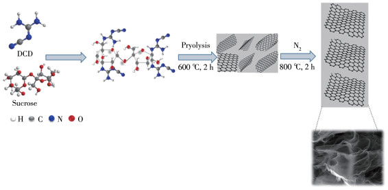
The catalyst was prepared by a facile hightemperature pyrolysis of the mixture that was composed of DCD and different carbon sources. In a typical preparation using sucrose as the carbon source, 3.0 g DCD was firstly dissolved in 50 mL water to form a uniform solution, then 0.32 g sucrose was added under stirring until it was completely dissolved. After stirring for 2 h at 50 ℃, the mixture was placed in an open crucible and heated at 75 ℃ for 24 h. After full grinding, the obtained solid mixture was transferred to the tubular furnace and heated to 600 ℃ at the rate of 4 ℃·min-1 in N2 atmosphere. After keeping 600 ℃ for 2 h, the furnace was then heated up to 800 ℃ and maintained at that temperature for another 2 h. After the temperature dropped to room temperature, the collected samples were recorded as CN-nanosh(suc) where“suc”means sucrose. Similarly, by replacing sucrose with β- cyclodextrin and chitosan, corresponding samples, marked as CN-nanosh(cyc) and CN-nanosh(ch) respectively, were obtained under the same preparation processes. All samples revealed a similar synthetic yield of 47%~50% relative to the mass of carbon source.
SEM and TEM images of the prepared catalysts were obtained with field emission scanning electron microscopy (Zeiss Merlin Compact-61-78) operated at 10 kV and transmission electron microscopy (JEM - 2100F, Japan) operated at 200 kV, respectively. Composition analyses for the samples were carried out by X- ray diffractometer (XRD, Ultima Multipurpose X - Ray Diffraction System Ⅳ, Rigaku, Japan) with Cu Kα radiation (λ=0.154 nm) at a generator voltage of 40 kV and a generator current of 40 mA with a scanning speed of 5 (°) ·min-1 from 10° to 90° and X -ray photoelectron spectroscopy (XPS, K-Alpha 1063). AFM images were obtained on an atomic force microscopy (AFM, Bruker dimension icon). Surface area measurement was performed via Brunauer-Emmett-Teller (BET, 3H-2000PM2, China). Raman spectra were analyzed with Andor SR-500i.
A classic three-electrode test system was applied to perform electrochemical experiments on Autolab PGSTAT30/FRA electrochemical workstation (the Netherland). The working electrode was glassy carbon (GC, 0.125 6 cm2 geometric area) coated with catalyst ink, and the auxiliary and reference electrodes were Pt foil with a large area and Ag/AgCl (saturated KCl) respectively. Potentials on rotating disk electrode (RDE) polarization curves were against the Ag/AgCl. Geometrical area of the working electrode (or air electrode in battery test) was applied to figure up the current density (or power density). Fabrication of the working electrode includes the following steps: (1) polishing of the GC electrode with Al2O3 powder and subsequent washing with pure water, (2) preparation for the fine suspension ink of the catalyst by ultra - sonicating the mixture of 5 mg of catalyst sample, 5 μL of 5%(mass fraction) Nafion and 950 μL ethanol for 1.5 h, and (3) transferring of 20 μL of the ink onto the surface of the GC electrode and drying at room temperature to obtain the working electrode. The catalyst loading on the GC electrode was 0.80 mg·cm2. As comparison, commercial Pt/C loaded GC electrode was also fabricated by using the same process and Pt mass loading on GC was 0.2 mg·cm2. The test of ORR electroactivity of the prepared catalysts was carried out in 0.1 mol·L-1 KOH.
A homemade alkaline Zn - air battery was assembled, which was composed of the cathode (air electrode), the anode (zinc sheet) and the electrolyte (6 mol·L-1 KOH solution). Carbon cloth was used to fabricate the air electrode: the catalyst ink was coated on one side of the carbon cloth. Fig. 1 shows the abridged general view of the battery, where one side of the air electrode coated by the catalyst acted as the catalytic layer (CL) and kept in touch with the electrolyte solution, and another side with no catalyst as the gas diffusion layer (GDL) kept in directly contact with air. A program-controlled battery tester (CT-4008-5V50 mA- 164, NEWARE, China) was used to test and evaluate the performance of the as-made Zn-air battery. All measurements including ORR activity and battery performance were carried out at room temperature.
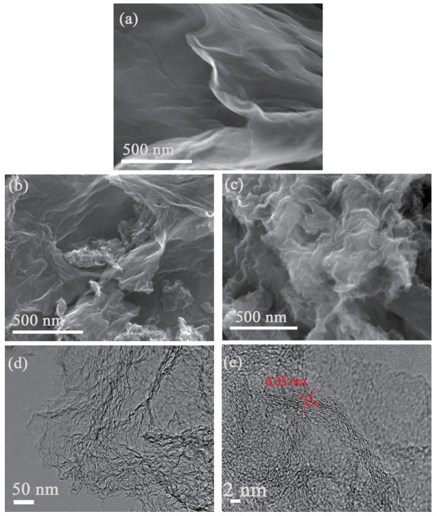
The morphology and microstructure of the obtained catalysts were observed by SEM and TEM. Fig. 2a~2c present the SEM images of the obtained catalysts CN-nanosh(suc), CN-nanosh(cyc) and CN-nanosh (ch). It can be clearly observed from the SEM images that the catalysts exhibit a sheet-like texture analogous to the soft silk. These silk-like nanosheets are formed from typical graphene - like nanolayer particles. Main compositions of the nanosheets are carbon and nitrogen from DCD. Compared with the other two samples, the sheet structure of the catalyst CN-nanosh(suc) in Fig. 2a was clearer and the surface was smoother. The wrinkles on the edges were more obvious. The transparent tulle structure can be more clearly observed from its TEM image (Fig. 2d). It had a layered and pleated structure with more exposed edges, which provides a suitable location for the N-doped carbon matrix[29]. Fig. 2b, 2c also reveals that the edge portions had a small number of wrinkles, which were more stacked together. Especially, there was an obvious agglomeration between the layers of catalyst CN- nanosh(ch) as indicated in Fig. 2c. This reduces the surface area of the catalyst and the results are further verified by the BET surface area data. Fig. 2d displays the TEM image of the catalyst CN - nanosh(suc), which clearly exhibited the transparent tulle-like sheets and took on many wrinkles originated from a layered structure. This will help the catalyst to expose more active sites and ensure the adequate contact between the active sites and the electrolytes, leading to the enhancement of the ORR. The HRTEM image (Fig. 2e) illustrates that the spacing of the discernible lattice fringes was about 0.35 nm, analogous to the (002) plane lattice plane of graphitic carbon.
Pyrolysis preparation of the C- N hybrid composites was achieved by a facile sacrificial template method[30]. Herein, C-N nanosheet composites were obtained by direct pyrolysis of the mixture of DCD and carbon source, which is illustrated in Scheme 1 using sucrose as a typical carbon source, where DCD acts as a nitrogen source and a sacrificial template precursor. After undergoing stepwise thermal decomposition, the g-C3N4 polymers were first formed at the temperature lower than 600 ℃ and the mixture was finally transferred into nanosheet composites with the temperature increasing to 800 ℃[25].
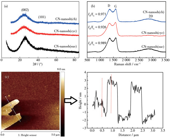
XRD patterns were also recorded and applied to characterize the crystal structure of all samples as indicated in Fig. 3a. The XRD patterns show that two broad peaks at 25.1° and 42.8° can be assigned to the reflection of (002) plane and (101) planes of graphitic carbon, respectively[31-32]. Also, the observed (002) plane diffraction peak was around 25.1°, displaying a slight decline compared to the (002) plane peak of standard graphite (26.6°) (PDF No.47-1743). This negative shift of the (002) plane peak reflects an enlarged interfacial distance. It should be noted from many reports that the (002) plane peak in the expanded carbon material corresponds to amorphous carbon[33-34]. Combined with the above structural features, broadening the (002) plane diffraction peaks of the synthesized catalysts should be explained by their significantly reduced thickness and enlarged interplanar spacing. In addition to the enlarged layer spacing, crystals are imperfect due to the nitrogen doping. The enlarged (002) plane peak reveals that the distribution of the interlayer distance for the catalysts has residual functional groups, which is caused by the abundant surface defects[35]. In addition, a weak peak of (101) plane at 42.8° was observed, indicating the formation of a graphite substrate for catalysts hybrids[36]. Fig. 3b presents Raman spectra of the catalysts under the 532 nm laser. For all the prepared catalysts, there were two significant peaks at around 1 358 and 1 586 cm-1 (Fig. 3b), which is attributed to the D and G band, respectively. The band associated with the E2g vibration mode of the G - band and the sp2 carbon domain can be used to indicate the degree of graphitization, while the D - band is structurally deficient and the disordered structure of the partially related sp2 domain[37]. Their strength ratios in ID/IG are widely used to indicate structural defects in carbon materials and to demonstrate the extent of graphitized carbon materials. The large ratio of ID/IG indicates that carbon materials have abundant surface defects[38-39]. Also, the number of graphene layers can be distinguished according to the position and shape of the 2D peak in the Raman spectrum. In Fig. 3b, the 2D peak appeared near 2 700 cm-1, which was very weak and hardly observable. All samples exhibited broad 2D bands, suggesting low order of carbon. This is common in carbon-based materials prepared by pyrolysis[40]. The results from AFM analyses reveal that the CN-nanosh(suc) sample is composed of a multilayer graphene structure[41]. The ID/IG values of the CN-nanosh(suc), CN-nanosh(cyc) and CN- nanosh(ch) are about 0.989, 0.926 and 0.971 respectively, which demonstrates the presence of certain graphitized carbon structures and defect sites in the material[42]. Generally, the larger ID/IG ratio of the CN- nanosh(suc) composite indicates more defect sites. As the nitrogen atom destroys the carbon layer of the car-bon material and is doped to the carbon surface, the edge plane of the graphene-like sheet structure will be exposed and structural defects arise. Also, more structural defects of the material will be formed if nitrogen with higher content is doped. The results show that these active sites are conducive to the enhancement of ORR electrocatalytic activity. The AFM image in Fig. 3c demonstrated the smooth surface of CN-nanosh (suc), which showed a nanosheet thickness of 3.05 nm for the CN-nanosh(suc), corresponding to about 9 layers of graphene sheets. Such ultra-thin thicknesses can create many exposed active surfaces and provide a powerful way to reduce charge transfer resistance of ORR.
N2 adsorption-desorption isotherms and pore size distribution curves were obtained and analyzed for the prepared samples to evaluate their specific surface area and porosity. As shown in Fig. 4a~4c, a layered porous structure with a high specific surface area showed a typical type Ⅳ isothermal curve with significant hysteresis, indicating the presence of abundant mesopores[42-43]. The specific surface area, average pore size and pore volume of all samples are shown in Table 1. The BET surface area/pore volume of the CN-nanosh (suc), CN- nanosh(cyc) and CN- nanosh(ch) were reck- oned to be 433 m2·g-1/1.5 cm3·g-1, 404 m2·g-1/1.1 cm3· g-1 and 289 m2·g-1/0.7 cm3·g-1, respectively. The high specific surface area and large pore volume of CN - nanosh(suc) help to expose more active sites and facilitate the transfer of reactants and products, which is beneficial to the oxygen reduction reaction. Additionally, the Barrett-Joyner-Halenda (BJH) pore size distribution plots showed a similar trend of pore sizes smaller than 4 nm for the all prepared catalysts, validating that the materials contain massive nanopores and mesopores. Indeed, a porous structure is advantageous for promoting the adsorption of the active species[44-45]. A large surface area of the catalyst will produce more active sites, while a hierarchical porous structure facilitates rapid proximity of the reactant molecules to the active sites, resulting in enhanced electrocatalytic activity.
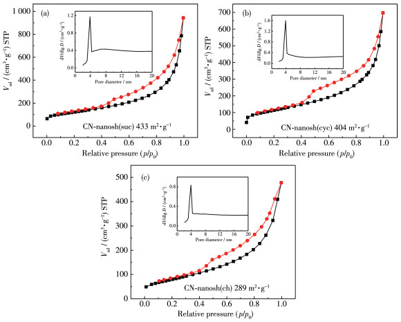
Insets in (a~c) show the corresponding BJH pore size distribution plots
 下载:
导出CSV
下载:
导出CSV
| Sample | Specific surface area / (m2·g-1) | Average pore diameter / nm | Pore volume / (cm3·g-1) |
| CN-nanosh(suc) | 433 | 10 | 1.5 |
| CN-nanosh(cyc) | 404 | 8 | 1.1 |
| CN-nanosh(ch) | 289 | 7 | 0.7 |
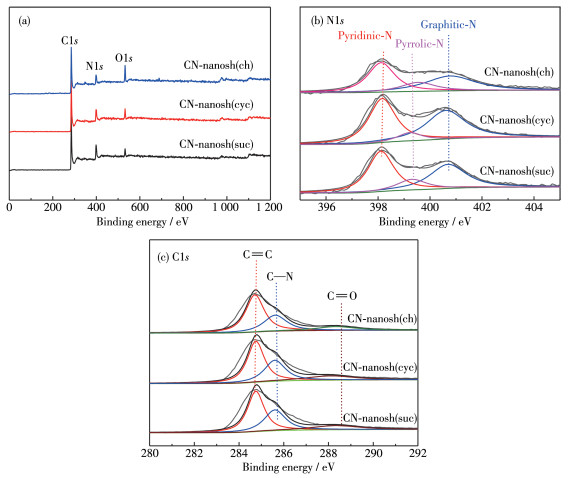
Chemical composition and structure of the pre- pared catalysts were further analyzed by XPS technique. The XPS survey spectra reveal the presence of C, N, O elements as shown in Fig. 5a. The N elemental contents measured by XPS were 16.53%, 11.54% and 13.28% (atomic fraction) for the respective CN-nanosh (suc), CN-nanosh(cyc) and CN-nanosh(ch) catalysts, indicating that N atoms are successfully incorporated into the carbon skeleton to form N-doped carbon (Table 2). The higher N content of the CN-nanosh(suc) can produce more active sites and defects, which is consistent with its Raman analysis (Fig. 3b). The highresolution N1s spectra of the samples shown in Fig. 5b can be deconvoluted into three peaks near 398.16, 399.22 and 400.65 eV, corresponding to pyridine N, pyrrole N and graphite N respectively[46-47]. This means that after calcination at high temperature, the N species exists in a more stable form. Presence of the pyridine-N and graphite-N species further confirm that the heteroatoms are doped in the carbon skeleton by in situ embedding. Among the prepared samples, the catalyst CN-nanosh(suc) exhibited the highest contents of both total N and pyridine N. It is well known that the nitrogen configuration has a large impact on the structure and the activity of the resulting material[48-49] and homol- ogous results are shown in Table 2. High content of pyridine-N can change the electron delocalization effect of carbon atoms and reduce the loss of electron transfer energy, leading to the effective enhancement of the electron transfer. Graphite-N can improve the mobility and conductivity of the catalyst. Further research shows that graphite N contributes to the increase of current density, and pyridine N helps to increase the initial potential of ORR[50-51]. The high resolution C1s XPS spectra are shown in Fig. 5c. The peaks at 284.7, 285.6 and 288.3 eV are related to C=C, C—N and C=O bonds, respectively[52]. The peak at 284.7 eV in C1s spectra corresponds to sp2 hybridized graphite carbon atoms and the peak at 285.6 eV is attributed to the C—N bond, indicating the successful doping of nitrogen into the carbon matrix[53]. Generally, pyridine and pyrrole nitrogen exist on the edge of a graphite layer, and they are usually believed to be presented in the π-conjugated system and make contribution to the aromatic π-conjugated system with one or two electrons. And excess electrons are delocalized in the π - conjugated system, which may lead to the improvement of the electronic conductivity[54-55]. According to the earlier literature, graphite N and pyridine N are active on ORR, which contributes to the oxygen reduction process by enhancing the adsorption of O2 and weakening the O—O bond[56-58]. The uniform distribution of abundant active sites on the mesoporous carbon surface can significantly enhance electron penetration, thereby increasing the ORR catalytic activity. Moreover, the presence of a high proportion of pyridine N and graphite N is generally more helpful in promoting the oxygen reduction reaction[59]. Therefore, the prepared nitrogen doped grapheme-like lamellar composites can be used as the excellent electrocatalysts of ORR.
下载:
导出CSV
| Sample | Atomic fraction / % | |||
| Total N | Pyridine N | Pyrrole N | Graphite N | |
| CN-nanosh(suc) | 16.53 | 46.66 | 14.11 | 39.25 |
| CN-nanosh(cyc) | 11.54 | 43.01 | 16.89 | 40.01 |
| CN-nanosh(ch) | 13.28 | 40.45 | 2.11 | 57.44 |
The ORR activities of the prepared catalysts were assessed using RDE technique in O2-saturated 0.1 mol· L-1 KOH. Results were also compared with the commercial Pt/C catalyst. In the alkaline electrolyte (Fig. 6a), the half-wave potentials of CN - nanosh(suc), CN-nanosh(cyc), CN-nanosh(ch) and Pt/C were -0.20, -0.21, -0.21 and -0.11 V, respectively. Their limiting diffusion current densities at -0.51 V were 5.56, 5.11, 4.46 and 4.77 mA·cm-2, respectively. Also, the CN-nanosh(suc) catalyst presents a lower Tafel slope of 126 mV·dec-1 than the CN - nanosh(cyc) (147 mV· dec-1) and CN - nanosh(ch) (138 mV·dec-1) (Fig. 6b). Results exhibit the better electroactivity of the catalyst CN-nanosh(suc) for ORR than the catalysts CN-nanosh(cyc) and CN-nanosh(ch), which may be related to the higher pyridine N content and BET surface area value of the CN-nanosh(suc). Although the CN-nanosh(suc) presents a less half-wave potential than Pt/C, its diffusion current density is larger than Pt/ C. Further, the CN-nanosh(suc) and Pt/C were investigated for the tolerance of methanol as indicated in Inset of Fig. 6b. Results reveal that ORR on Pt/C was severely depressed in the presence of methanol due to the oxidation of methanol, showing poor methanol tolerance of Pt/C. On the contrary, no significant change was observed on the LSV (linear scan polarization) curve of the CN-nanosh(suc) in absence or presence of methanol, displaying its excellent methanol tolerance.
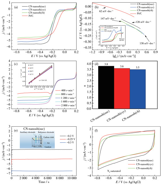
The ORR kinetic polarization curves of CN-nanosh(suc) at different speeds are depicted in Fig. 6c. A well - defined current plateau appeared and the plateau current increased with the rotting speed. The limiting current density at 2 000 r·min-1 reached 5.56 mA·cm-2 in the alkaline solution. Koutecky-Levich (K-L) plots at different potentials can be obtained based on the following K-L equation[60]:
|
$ \frac{1}{j} = \frac{1}{{{j_{\rm{L}}}}} + \frac{1}{{{j_{\rm{K}}}}} = \frac{1}{{B{\omega ^{1/2}}}} + \frac{1}{{{j_{\rm{K}}}}} $ |
(1) |
|
$ B = 0.2nF{c_0}D_0^{2/3}{v^{ - 1/6}} $ |
(2) |
where j is the measured current density, jK is the kinetic current density, jL is the diffusion-limiting current density, ω is the electrode rotation rate (ω unit is r· min-1), n is the transferred electron number, F is the Faraday constant (96 485 C·mol-1), c0 is the bulk concentration of O2 (1.2×10⁻⁶ mol·cm-3 for 0.1 mol·L-1 KOH), D0 is the diffusion coefficient of O2 (1.9×10⁻⁵ cm2·s-1 in 0.1 mol·L-1 KOH), and ν is the kinematic viscosity of the electrolyte (1.0×10⁻² cm2·s-1 for 0.1 mol·L-1 KOH). The corresponding results are shown in the inset of Fig. 6c. According to the K-L equation and the parameters in the literature[60], the n of ORR on CN-nanosh(suc) was calculated to be 3.8 in alkaline medium on the basis of LSVs (LSVs curves) of the CN - nanosh(suc) at differented rotation rates (from 400 to 2 000 r·min-1) (Fig. 6c), indicating that the ORR process on CN-nanosh(suc) is almost a four-electron path in an alkaline medium. The n of ORR on other catalysts are also acquired and shown in Fig. 6d, which exhibited a nearly complete reduction of oxygen on all the prepared catalysts. The stability of the ORR activity of CN - nanosh(suc) in practical Zn - air battery was further studied by chronoamperometry at different potentials as shown in Fig. 6e. The tests were performed in a three-electrode system where the carbon cloth coat- ed with the CN-nanosh(suc) catalyst as the working electrode[21-22]. The rapid decrease of current density in the initial stage is caused by the fast consumption of O2 at the air electrode/electrolyte interface. After about 2 min, the current density remained a nearly constant value. The results show that the prepared sample has excellent stability in alkaline solution and can be used as the cathode of Zn-air battery. Further, the prepared catalysts displayed higher electrical conductivity, indicated by their larger capacitive current background in N2-saturated 0.1 mol·L-1 KOH solution (Fig. 6f)[16]. This could be attributed to the presence of a certain degree of graphitized carbon in the catalysts.
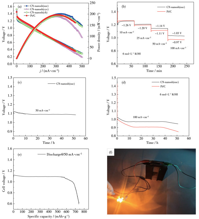
In order to study the potential application of the prepared catalyst in an alkaline electrolyte, a Zn - air battery was constructed with Zn sheet as an anode, a carbon cloth loaded by the prepared catalyst as an air cathode and 6.0 mol·L-1 KOH as an electrolyte (Fig. 7a). As a contrast, Pt/C was also examined as a cathode catalyst. Fig. 7b shows the polarization and power density curves for Zn-air batteries in 6.0 mol·L-1 KOH with different cathode catalysts. When the current density was 333.95 mA·cm-2, the CN-nanosh(suc) battery can deliver a maximum power density of 201.33mW·cm-2. For comparison, Pt/C displayed a maximum power density of 196.34 mW·cm-2. When the test voltage dropped to 0.2 V, the corresponding discharge current density reached 500 mA·cm-2, which shows better performance than those recently reported[61-62]. The open -circuit voltage (OCV) of the CN-nanosh(suc) was 1.46 V, which exceeds Pt/C (1.45 V). In addition, the step discharge curves of the batteries with CN-nanosh(suc) and Pt/C cathodes in 6.0 mol·L-1 KOH were recorded at different current densities of 10, 25, 50 and 100 mA· cm-2 (Fig. 7b). A clear voltage plateau was formed at any discharge current, showing a high discharging stability of the battery. At low current densities of 10 and 25 mA·cm-2, the voltage plateaus of the CN-nanosh (suc) battery were very close to those of the Pt/C battery. Further, when the discharge current densities of the CN - nanosh(suc) battery were higher (50 and 100 mA·cm-2), the corresponding voltage plateaus of the CN-nanosh(suc) battery became higher than those of the Pt/C battery. This is consistent with the ORR electroactivity tests of the catalysts shown in Fig. 6a, where the ORR potential of Pt/C was higher than that of the CN-nanosh(suc) catalyst at low current density. In order to further verify the stability of the air electrode using CN - nanosh(suc) catalyst during longterm operation of the battery, constant current discharge of CN-nanosh(suc) and Pt/C batteries was tested as indicated in Fig. 7c and 7d. At the current density of 50 mA·cm-2 (Fig. 7c), the CN - nanosh(suc) catalyst showed almost no voltage drop with time, and the volt- age remains approximately 1.09 V after the discharging time of 50 h. As for the higher current density like 100 mA·cm-2 (Fig. 7d), the CN-nanosh(suc) and Pt/C cata- lysts assumed an overt voltage decline at the initial 7 and 13 h discharge stages respectively. Subsequently, a highly stable discharge voltage arose, until the discharge time exceeded 40 h. The faster decline of the battery voltage after 40 h would be related to the con- sumption of anode Zn and electrolyte. This is fully sup- ported by keeping the air electrode unchanged and replacing the anode Zn and electrolyte to get similar discharge curves. Results indicate that the alkaline Zn- air battery with the cathode catalyst CN - nanosh(suc) has a long - lasting and stable discharge performance even at a high current density of 100 mA·cm-2. Finally, as shown in Fig. 7e, the specific capacity of the battery equipped with CN-nanosh(suc) can reach to 740 mAh·g-1. Electrochemical performances of the CN-nanosh(suc) and the recently reported catalysts were summarized in Table 3. Compared with the cata- lysts reported, the CN - nanosh(suc) reveals similar or even superior electroactivity. Further, the prepared CN- nanosh(suc) was applied to a battery to investigate its practical performance. As shown in Fig. 7f, two alkaline CN - nanosh(suc) batteries can easily illuminate two LEDs (LED 3V) for a long time. The high ORR catalytic activity and stability of CN-nanosh(suc) makes it an advanced cathode catalyst for alkaline Zn - air battery and other related fuel cells.
 下载:
导出CSV
下载:
导出CSV
| Catalysta | OCV / V | Power density /(mW·cm-2) | Specific capacity /(mAh·g-1) | Stable discharge time / h(Current density / (mA·cm-2)) | Reference |
| CN-nanosh(suc) | 1.46 | 201.33 | 740 | 50 (50) | This work |
| FeCo@MNC | 1.41 | 115 | — | 24 (20) | [63] |
| CoNi/BCF | 1.44 | 155.1 | 710.9 | 30 (10) | [64] |
| 1100-CNS | 1.49 | 151 | — | 55 (10) | [65] |
| NDGs-800 | 1.45 | 115.2 | 750.8 | 78 (10) | [66] |
| Mn/Fe-HIB-MOF | 1.48 | 195 | 769 | 1 000 (10) | [67] |
| TARC-N | 1.47 | 241 | — | 100 (10) | [68] |
| S-C2NA | 1.49 | 300 | 863 | 750 (10) | [69] |
| NGM-Co | 1.44 | 152 | 750 | 60 (2) | [70] |
| NPCTC-850 | 1.47 | 74 | 730 | 60 (5) | [71] |
| P, S-CNS | 1.51 | 198 | 830 | 100 (2) | [28] |
| PS-CNF | 1.49 | 231 | 698 | 120 (2) | [72] |
| a FeCo@MNC: mesoporous Fe/Co-N-C nanofibers with embedding FeCo; CoNi/BCF: CoNi supported by a butterfly wing-derived carbon framework; 1100-CNS: carbon nano-sheet pyrolyzed at 1 100 ℃; NDGs-800: pyridinic-N-dominated graphene pyrolysis at 800 ℃; Mn/Fe-HIB- MOF: Mn/Fe-hexaiminobenzene MOFs; TARC-N: trithiocyanuric acid (TA) after pyrolysis; S-C2NA: hierarchical three-dimensional sulfur-mod- ulated holey C2N aerogels; NGM-Co: Co/N/O tri-doped graphene mesh; NPCTC-850: N, P co-doped carbon nanotube cluster at 850 ℃; P, S- CNS: P and S-codoped carbon nitride sponge; PS-CNF: P and S-codoped carbon nitride interconnected nanofibers. | |||||
In summary, we have developed a simple and costeffective method for preparing layered porous C-N nanocomposites by directly pyrolyzing a mixture of DCD and various carbon sources like sucrose, β- cyclodextrin and chitosan. The nanocomposites exhibit a porous and graphene-like pleated structure. Also, they possess ultra-high specific surface areas and large contents of both active pyridinic-N and graphitic-N, ensuring their superior ORR electroactivity. Benefiting from its excellent ORR activity, the prepared CN-nano(suc) catalyst exhibits better performance than commercial Pt/C in alkaline Zn-air batteries at different discharge current densities. The Zn-air battery with cathode catalyst CN- nanosh(suc) provided the highest power density of 201.33 mW·cm-2, and it can discharge steadily over 50 h at the high current density of 100 mA·cm-2. Also, the specific capacity of the battery equipped with the cathodic catalyst CN-nanosh(suc) can reach to 740 mAh·g-1. Compared with Pt/C bat- tery, CN-nanosh(suc) battery had higher power density, discharge current density, discharge voltage plateau and stability. The simple method and scalability for synthesizing metal-free N-doped graphene-like carbon nanosheets provide a promising way for developing effective cathodic catalysts of various fuel cells and metal -air batteries.
Yuan W J, Li J H, Xie A J, Chen P, Li S K, Shen Y H. Electrochim. Acta, 2015, 165:29-35 doi: 10.1016/j.electacta.2015.02.242
Zhang J T, Zhao Z H, Xia Z H, Dai L M. Nat. Nanotechnol., 2015, 10(5):444-452
Zheng Y, Jiao Y, Chen J, Liu J, Liang L, Du A J, Zhang W M, Zhu Z H, Smith S C, Jaroniec M. J. Am. Chem. Soc., 2011, 133(50):20116-20119 doi: 10.1021/ja209206c
Zhan W C, Guo Y, Gong X Q, Guo Y L, Wang Y Q, Lu G Z. Chinese J. Catal., 2014, 35(8):1238-1250 doi: 10.1016/S1872-2067(14)60189-3
Chen Z, Higgins D, Chen Z G. Carbon, 2010, 48:3057-3065 doi: 10.1016/j.carbon.2010.04.038
Zhu H Y, Zhang S, Huang Y X, Wu L H, Sun S H. Nano Lett., 2013, 13(6):2947-2951 doi: 10.1021/nl401325u
Yi Q F, Zhang Y H, Liu X P, Xiang B L, Yang Y H. J. Mater. Sci., 2014, 49:729-736 doi: 10.1007/s10853-013-7754-2
Yi Q F, Zhang Y H, Liu X P, Yang Y H. Sci. China Chem., 2014, 57:739-747 doi: 10.1007/s11426-013-5027-1
Yu L, Yi Q F, Yang X K, Li G. Chemistry Select, 2018, 3:12603-12612
Wang Y C, Zhou T, Jiang K, Da P M, Zheng G F. Adv. Energy Mater., 2014, 4(16):1400696 doi: 10.1002/aenm.201400696
Fan X J, Peng Z W, Ye R Q, Zhou H Q, Guo X. ACS Nano, 2015, 9(7):7407-7418 doi: 10.1021/acsnano.5b02420
Ma T Y, Dai S, Jaroniec M, Qiao S Z. Angew. Chem., 2014, 126(28):7409-7413 doi: 10.1002/ange.201403946
Deng Z L, Yi Q F, Zhang Y Y, Nie H D. J. Electroanal. Chem., 2017, 803:95-103 doi: 10.1016/j.jelechem.2017.09.025
Gong K P, Du F, Xia Z H, Durstoch M, Dai L. Science, 2009, 323(5915):760-764 doi: 10.1126/science.1168049
Yu P P, Zhang Z M, Zheng L X, Teng F, Hu L F, Fang X S. Adv. Energy Mater., 2016, 6(20):1601111 doi: 10.1002/aenm.201601111
Lin Z Y, Song M K, Ding Y, Liu Y, Liu M L, Wong C P. Phy. Chem. Chem. Phy., 2012, 14(10):3381-3387 doi: 10.1039/c2cp00032f
Jin J T, Pan F P, Jiang L H, Fu X G, Sun G Q. ACS Nano, 2014, 8:3313-3321 doi: 10.1021/nn404927n
Preuss K, Kannuchamy V K, Marinovic A, Isaacs M, Wilson K, Abrahams I, Titirici M M. J. Energy Chem., 2016, 25:228-235 doi: 10.1016/j.jechem.2016.01.001
Wu H H, Wang J, Wang G X, Cai F, Ye Y F, Jiang Q K, Sun S C. Nano Energy, 2016, 30:801-809 doi: 10.1016/j.nanoen.2016.09.016
Zheng Y, Jiao Y, Li L H, Xing T, Chen Y, Jaroniec M, Qiao S Z. ACS Nano, 2014, 8:5290-5296 doi: 10.1021/nn501434a
Yang X K, Yi Q F, Sheng K, Wang T. Ionics, 2019, 25:4817-4830 doi: 10.1007/s11581-019-03022-4
Yu L, Yi Q F, Yang X K, Chen Y. Sci. China Mater., 2019, 62(9):1251-1264 doi: 10.1007/s40843-019-9439-9
Sheng K, Yi Q F, Hou L F, Chen A L. J. Electrochem. Soc., 2020, 167:070560 doi: 10.1149/1945-7111/ab8646
Wang Q C, Ji Y J, Lei Y P, Wang Y B, Wang Y D, Li Y Y, Wang S Y. ACS Energy Lett., 2018, 3(5):1183-1191 doi: 10.1021/acsenergylett.8b00303
Cao J Y, Hu Y, Chen L J, Xu J, Chen Z D. Int. J. Hydrogen Energy, 2017, 42(5):2931-2942 doi: 10.1016/j.ijhydene.2017.01.029
Zhang H M, Chen J Y, Li Y B, Liu P R, Wang Y, An T C, Zhao H J. Electrochim. Acta, 2015, 165:7-13 doi: 10.1016/j.electacta.2015.02.240
Chen D W, Zou Y Q, Wang S Y. Mater. Today Energy, 2019, 12:250-268 doi: 10.1016/j.mtener.2019.01.006
Shinde S S, Lee C H, Sami A, Kim D H, Lee S U, Lee J H. ACS Nano, 2017, 11(1):347-357 doi: 10.1021/acsnano.6b05914
Lai L F, Potts J R, Zhan D, Wang L, Poh C K, Tang C H, Gong H, Shen Z X, Lin J Y, Ruoff R S. Energy Environ. Sci., 2012, 5(7):7936-7942 doi: 10.1039/c2ee21802j
Meng Y, Gu D, Zhang F Q, Shi Y F, Zhao D Y. Angew. Chem. Int. Ed., 2005, 44(43):7053-7059 doi: 10.1002/anie.200501561
Deng Z L, Yi Q F, Li G, Chen Y, Yang X K, Nie H D. Electrochim. Acta, 2018, 279:1-9 doi: 10.1016/j.electacta.2018.05.069
Wei C T, Wang H J, Eid K, Kim J, Kim J H, Alothman Z A, Wang L. Chem.-Eur. J., 2016, 23:637-643
Yang J Q, Zhou X L, Wu D H, Zhao X D, Zhou Z. Adv. Mater., 2016, 29(6):1604108
Qie L, Chen W M, Xiong X Q, Hu C C, Zou F, Hu P, Huang Y H. Adv. Sci., 2015, 2(12):1500195
Tamilarasan P, Ramaprabhu S. J. Mater. Chem. A, 2015, 3(1):101-108
Xue H R, Wang T, Guo H, Fan X L. RSC Adv., 2014, 4(101):57724-57732 doi: 10.1039/C4RA09939G
Qu K, Zheng Y, Dai S, Qiao S Z. Nanoscale, 2015, 7(29):12598-12605 doi: 10.1039/C5NR03089G
Cong H P, Wang P, Gong M, Yu S H. Nano Energy, 2014, 3:55-63 doi: 10.1016/j.nanoen.2013.10.010
Ferrari A, Basko D M. Nat Nanotechnol., 2013, 8(4):235-246
Zhang N F, Zhou Y M, Yang X Y, Tang C L, Wu H, Zhong N S. RSC Adv., 2014, 4(34):17549-17554 doi: 10.1039/c3ra47853j
Yang C, Xu Y Y, Zhang C, Sun Z C, Chen C S, Li X H, Jiang S Z, Man B Y. Nanoscale Res. Lett., 2014, 9(1):394 doi: 10.1186/1556-276X-9-394
Yu H J, Shang L, Bian T, Shi R, Waterhouse G I N, Zhao Y F, Zhou C, Wu L Z, Tung C H, Zhang T R. Adv. Mater., 2016, 28(25):5140 doi: 10.1002/adma.201670178
Gupta S, Qiao L, Zhao S, Xu H, Lin Y, Devaguptapu S V, Wang X L, Swihart M T, Wu G. Adv. Energy Mater., 2016, 6(22):1601198 doi: 10.1002/aenm.201601198
Wang M, Yang Z Z, Wang J Q, Li H, Gu L, Yu Y. Small, 2015, 11(40):5330 doi: 10.1002/smll.201570245
Raccichini R, Varzi A, Passerini S, Scrosati B. Nat. Mater., 2014, 14(3):271-279
Ning R, Ge C J, Liu Q, Tian J Q, Asiri A M, Alamry K A, Li C M, Sun X P. Carbon, 2014, 78:60-69 doi: 10.1016/j.carbon.2014.06.048
Li J C, Zhao S Y, Hou P X, Fang R P, Liu C, Liang J, Cheng H M. Nanoscale, 2015, 7(45):19201-19206 doi: 10.1039/C5NR05998D
Wasalathilake K C, Galpaya D G, Ayoko G A, Yan C. Carbon, 2018, 137:282-290 doi: 10.1016/j.carbon.2018.05.036
Dettlaff A, Sawczak M, Klugmann-Radziemska E, Czylkowski D, Miotk R, Wilamowska-Zawłocka M. RSC Adv., 2017, 7(51):31940-31949 doi: 10.1039/C7RA04707J
Liu G, Li X G, Ganesan P, Popov B N. Electrochim. Acta, 2010, 55(8):2853-2858 doi: 10.1016/j.electacta.2009.12.055
Rao C V, Cabrera C R, Ishikawa Y. J. Phys. Chem. Lett., 2010, 1(18):2622-2627 doi: 10.1021/jz100971v
Tang C, Wang B, Wang H F, Zhang Q. Adv. Mater., 2017, 29(37):1703185 doi: 10.1002/adma.201703185
Wan K, Long G F, Liu, M Y, Du L, Liang Z X, Tsiakaras P. Appl. Catal. B, 2015, 165:566-571 doi: 10.1016/j.apcatb.2014.10.054
Choi C H, Park S H, Woo S I. Green Chem., 2011, 13(2):406-412
Sahraie N R, Paraknowitsch J P, Göbel C, Thomas A, Strasser P. J. Am. Chem. Soc., 2014, 136(41):14486-14497
Zhu C Z, Li H, Fu S F, Du D, Lin Y H. Chem. Soc. Rev., 2016, 45:517-531
Ai K, Liu Y L, Ruan C P, Lu L H, Lu G M. Adv. Mater., 2013, 25(7):998-1003
Yang Z, Yao Z, Li G F, Fang J Y, Nie H G, Liu Z, Zhou X M, Chen X A, Huang S M. ACS Nano, 2012, 6(1):205-211
Chen Z, Yu A P, Higgins D, Li H, Wang H J, Chen Z W. Nano Lett., 2012, 12:1946-1952
Fu G T, Cui Z M, Chen Y F, Li Y T, Tang Y W, Goodenough J B. Adv. Energy Mater., 2016, 7:1601172
Liu L Z, Zeng G, Chen J X, Bi L L, Dai L M, Wen Z H. Nano Energy, 2018, 49:393-406
Xu N N, Zhang Y X, Zhang T, Liu Y Y, Qiao J L. Nano Energy, 2019, 57:176-185
Li C L, Wu M C, Liu R. Appl. Catal. B, 2019, 244:150-158
Wan W J, Liu X J, Li H Y, Peng X Y, Xi D S, Luo J. Appl. Catal. B, 2019, 240:193-200
Pei Z X, Hong F, Huang Y, Xue Q Z, Yang C Y, Zhu M S, Wang Z F. Energy Environ. Sci., 2017, 10(3):742-749
Wang Q C, Ji Y J, Lei Y P, Wang Y B, Wang Y D, Li Y Y, Wang S Y. ACS Energy Lett., 2018, 3(5):1183-1191
Shinde S S, Lee C H, Jung J Y, Wagh N K, Kim S H, Kim D H, Lin C, Lee S U, Lee J H. Energy Environ. Sci., 2019, DOI: 10.1039/c8ee02679c
Tang Z J, Pei Z X, Wang Z F, Li H F, Zeng J, Ruan Z H, Huang Y, Zhu M S, Xue Q, Yu J, Zhi C Y. Carbon, 2018, 130:532-543
Shinde S S, Lee C H, Yu J Y, Kim D H, Lee S U, Lee L H. ACS Nano, 2018, 12(1):596-608
Tang C, Wang B, Wang H F, Zhang Q. Adv. Mater., 2017, 29(37):1703185
Li Y M, Yan Z, Wang Q D, Ye H T, Li M L, Zhu L W, Cao X B. Electrochim. Acta, 2018, 282:224-232
Shinde S, Yu J Y, Song J W, Nam Y H, Kim D H, Lee D H. Nanoscale Horiz., 2017, 2(6):333-341

Figure 2 SEM images of CN-nanosh(suc) (a), CN-nanosh(cyc) (b) and CN-nanosh(ch) (c); TEM (d) and HRTEM (e) images of CN-nanosh(suc)

Figure 3 XRD patterns (a) and Raman spectra (b) of the samples, and AFM image of CN-nanosh(suc) (c)

Figure 4 N2 adsorption-desorption isotherms of CN-nanosh(suc) (a), CN-nanosh(cyc) (b) and CN-nanosh(ch) (c)
Insets in (a~c) show the corresponding BJH pore size distribution plots

Figure 6 Linear polarization curves (a) of the prepared catalysts and Pt/C on RDE in O2-saturated 0.1 mol·L-1 KOH at 1 600 r·min-1 at 5 mV·s-1, Tafel plots for ORR catalysis (b), Inset of (b) shows the effect of methanol on ORR performance of CN-nanosh(suc) and Pt/C at 1 600 r·min-1 by rapidly injecting methanol into the solution to reach 0.5 mol·L-1 methanol; RDE polarization curves (c) of CN-nanosh(suc) at different rotation rates in O2-saturated 0.1 mol·L-1 KOH at 5 mV·s-1, Inset of (c) is the corresponding K-L plots for CN-nanosh(suc) at different speeds; Electronic transfer numbers of ORR on the prepared catalysts (d), chronoamperograms (e) of the CN-nanosh(suc) catalyst in 0.1 mol·L-1 KOH in a half-cell system (Inset of (e)) where working electrode was the carbon cloth coated with the CN-nanosh(suc) catalyst. CVs in N2-saturated 0.1 mol·L-1 KOH at a scan rate of 50 mV·s-1 (f)

Figure 7 (a) Polarization and power density curves of the Zn-air battery with the cathodic catalysts of the prepared samples and Pt/C in 6 mol·L-1 KOH; (b) Discharge curves of the CN-nanosh(suc) and Pt/C batteries in 6 mol·L-1 KOH at different current densities; (c) 50 h discharging of the CN-nanosh(suc) battery in 6 mol·L-1 KOH under 50 mA·cm-2 current density; (d) 50 h discharging of the CN-nanosh(suc) and Pt/C batteries in 6 mol·L-1 KOH under 100 mA·cm-2 current density; (e) Constant current discharge curve until full depletion of the anode zinc foil; (f) Photograph of two LED (3 V) connected to two batteries with the cathode catalyst CN-nanosh(suc)
Table 1. BET characterization of all catalyst
| Sample | Specific surface area / (m2·g-1) | Average pore diameter / nm | Pore volume / (cm3·g-1) |
| CN-nanosh(suc) | 433 | 10 | 1.5 |
| CN-nanosh(cyc) | 404 | 8 | 1.1 |
| CN-nanosh(ch) | 289 | 7 | 0.7 |
 下载: 导出CSV
Table 2. Analysis of nitrogen element from XPS data
| Sample | Atomic fraction / % | |||
| Total N | Pyridine N | Pyrrole N | Graphite N | |
| CN-nanosh(suc) | 16.53 | 46.66 | 14.11 | 39.25 |
| CN-nanosh(cyc) | 11.54 | 43.01 | 16.89 | 40.01 |
| CN-nanosh(ch) | 13.28 | 40.45 | 2.11 | 57.44 |
下载: 导出CSV
Table 3. Performance of primary Zn⁃air batteries with various cathodic electrocatalysts
| Catalysta | OCV / V | Power density /(mW·cm-2) | Specific capacity /(mAh·g-1) | Stable discharge time / h(Current density / (mA·cm-2)) | Reference |
| CN-nanosh(suc) | 1.46 | 201.33 | 740 | 50 (50) | This work |
| FeCo@MNC | 1.41 | 115 | — | 24 (20) | [63] |
| CoNi/BCF | 1.44 | 155.1 | 710.9 | 30 (10) | [64] |
| 1100-CNS | 1.49 | 151 | — | 55 (10) | [65] |
| NDGs-800 | 1.45 | 115.2 | 750.8 | 78 (10) | [66] |
| Mn/Fe-HIB-MOF | 1.48 | 195 | 769 | 1 000 (10) | [67] |
| TARC-N | 1.47 | 241 | — | 100 (10) | [68] |
| S-C2NA | 1.49 | 300 | 863 | 750 (10) | [69] |
| NGM-Co | 1.44 | 152 | 750 | 60 (2) | [70] |
| NPCTC-850 | 1.47 | 74 | 730 | 60 (5) | [71] |
| P, S-CNS | 1.51 | 198 | 830 | 100 (2) | [28] |
| PS-CNF | 1.49 | 231 | 698 | 120 (2) | [72] |
| a FeCo@MNC: mesoporous Fe/Co-N-C nanofibers with embedding FeCo; CoNi/BCF: CoNi supported by a butterfly wing-derived carbon framework; 1100-CNS: carbon nano-sheet pyrolyzed at 1 100 ℃; NDGs-800: pyridinic-N-dominated graphene pyrolysis at 800 ℃; Mn/Fe-HIB- MOF: Mn/Fe-hexaiminobenzene MOFs; TARC-N: trithiocyanuric acid (TA) after pyrolysis; S-C2NA: hierarchical three-dimensional sulfur-mod- ulated holey C2N aerogels; NGM-Co: Co/N/O tri-doped graphene mesh; NPCTC-850: N, P co-doped carbon nanotube cluster at 850 ℃; P, S- CNS: P and S-codoped carbon nitride sponge; PS-CNF: P and S-codoped carbon nitride interconnected nanofibers. | |||||
下载: 导出CSV

 扫一扫看文章

扫一扫关注我们