Figure 1.
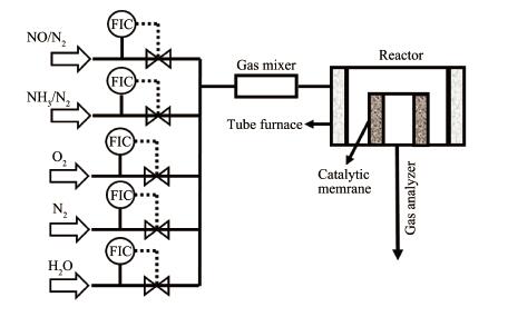
Scheme of the test device for the measurement the performance of the catalytic ceramic filter
Ordered Mesoporous and Complete Amorphous Ce-Ti Catalytic Filter for Particle Separation and NOx Removal
Dan LI , Hui WANG , Liu-Ping CHEN , Na ZHU

Nitrogen oxides (NOx) and particulates, emitted from the industrial combustion of fossil fuels, are main atmospheric pollutants, causing a variety of environ-mentally harmful effects such as acid rain, smog and PM2.5[1-2]. In traditional cleaning systems, the NOx abate-ment and dust removal mainly employ the selective cat-alytic reduction (SCR) and filtration technology, respec-tively, and the dust removal usually performs after the SCR process because the reaction temperature of the catalyst is between 250 and 350 ℃[3-5]. As a result, plugging and poisoning the SCR catalyst are easily occurred under high dust system, decreasing the ser-vice life of the catalyst. To address the problems men-tioned above, highly effective catalysts loaded on the porous ceramic filter was proposed for simultaneous removal of particulates and NOx[6-8]. Generally, the cata-lytic membrane is mainly comprised of separation layer and support layer. The dust removal was attributed to the separation layer and the catalyst was integrated into the support layer for the NOx abatement. To guar-antee the performance of the catalytic membrane, developing highly effective catalyst is of critical impor-tance.
Up to now, the widely used commercial catalyst in SCR is V 2 O5-WO3/TiO2. Nevertheless, there are same inevitable drawbacks, such as the toxicity of vanadium and inferior performance at low temperature, hindering their wide application[9-10]. In this regard, environment-friendly catalysts with wide temperature window were designed for the NOx removal, such as MnO x, CeO2, Fe2O3 and CuO[11-14]. Among that, CeO2 based catalyst attracts increasing attention because of their excellent reducibility and oxygen storage capacity[15-17]. Neverthe-less, pure CeO2 catalyst can facilitate the side reaction of NH3 oxidation and thereby decrease the SCR catalyt-ic activity. Recent studies have indicated that the Ce-Ti oxides catalyst presented excellent NOx conversion efficiency in a wide temperature range, especially the amorphous Ce-Ti oxides with the formation of new Ce-O-Ti active site[18-19]. Apart from the composition, the per-formance of the catalyst is also highly related to the microstructure. For instance, the Ce-Mn oxide nano-sphere catalyst demonstrated higher SCR performance than that of Ce-Mn oxide catalyst with a particle struc-ture[20]. The Mn-Fe catalyst with a nanocage structure delivered a superior SCR performance[21]. Moreover, ordered mesoporous catalysts have also attracted great attentions owing to the open pore framework and high surface area. It has demonstrated that the mesoporous catalyst can enhance the catalytic activity and broaden the temperature range for the SCR catalyst[22]. Herein, it is a great potential for cerium based SCR catalyst by combining the titanium oxides with ordered mesopo-rous structure.
In this work, complete amorphous Ce-Ti oxide series catalyst with highly ordered mesoporous struc-ture for the SCR of NOx with ammonia was synthesized via a template assisted sol-gel route. The catalyst microstructure and morphology was investigated in de-tail. The obtained catalyst exhibited approximately 100% NO conversion efficiency in a wide temperature range and excellent resistance to SO2. Subsequently, the catalyst was integrated into the support layer of a rigid ceramic membrane by a wet impregnation proce-dure for simultaneous removal of particulates and NOx.
A series of Ti-Ce mixed catalysts was obtained via a template assisted sol-gel process. Hydrochloric acid (HCl) was added drop wise to tetraethyl titanate (Ti(OC2H5)4) under vigorous stirring at 30 ℃. A solution of n-butyl alcohol (C4H9OH) with tri-block copolymer F127 and certain concentrations of Ce(NO3)3·6H2O was then added into it and the stirring was maintained for 2 h to obtain a transparent sol. The molar ratio of nTi(OC2H5)4: nC4H9OH:nHCl:nF127:nCe(NO3)3·6H2O was 1:6:9:0.005:(0~0.2) (denoted as CeaTiOx, where a was the Ce molar fraction). Subsequently, the sol was poured into the Petri-dishes and dried at 20 ℃ and 80%RH for 24 h to form a thin gel layer. The gel was then calcined in air for 450 ℃ for 4 h with the heating and cooling rate of 0.5 ℃·min-1 to obtain the catalyst. For comparison, the CeaTiOx catalyst without adding template F127 was also prepared and denoted as Bla-CeaTiOx.
An unsymmetrical SiC-SiO2 based porous ceramic with a dimension 60/40 nm×100 mm (outer/inner diam-eter×length) and an average pore size of 20 μm was provided by Jiulang High-technology company (Nanjing China). The Ce0.2TiOx sol was employed as cat-alyst precursor solution. The catalytic ceramic filter was prepared by a vacuum suction dip-coated method. To guarantee the catalytic activity, the coating procedure was repeated to increase the catalyst loading amount, denoted as CeaTiOx-M-N (N was coating times), and the loading catalyst was detected by a weighing method.
The crystal phase of the catalysts were determined by X-ray diffraction (XRD) test using a Bruker D8 Advance X-ray diffractometer with Cu Kα radiation (λ= 0.154 nm) at 40 kV and 30 mA between 20° to 80°. Small-angle X-ray diffraction (SAXRD) patterns of the catalysts were obtained from X-ray diffractometer at 40 kV and 200 mA between 0.5° to 5° (Ultima IV/PSK with Cu Kα radiation, λ=0.154 nm). The pore structure of the samples was measured by the transmission elec-tron microscopy (TEM) on a JEOL JEM-2100 electron microscope at an accelerating voltage of 200 kV. The surface area, pore volume and pore size of the catalysts were obtained using a BELSORPII N2 adsorption/ desorption apparatus at 77 K. The catalyst chemical composition was analyzed by X-ray photoelectron spec-troscopy (XPS, AXIS-Ultra, Al Kα 1 486.6 eV photons, 15 mA, 15 kV). The surface morphology of the catalytic membrane was obtained by a Hitachi S4800 field emis-sion scanning electron microscope (FE-SEM) with an accelerating voltage of 3 kV.
The gas permeation of the catalytic membrane with a length of 100 mm was investigated using a home-made equipment. The SCR activity of the catalytic membrane with a length of 20 mm was examined on a laboratory test device (Fig. 1). The model gas was used for the examinations containing 500 mg·L-1 NH3, 500 mg·L-1 NO, 3% (volume fraction) O2, 5% (volume frac-tion) H 2O and N2 as carrier gas, with a temperature ranged from 25 to 400 ℃ at a gas filtration velocity range of 4~10.6 cm·s-1. In addition, the NO concentra-tions was analyzed by a FTIR analyzer, and the NO conversion (XNO) was calculated according to the Eq. 1 Where cNO-in and cNO-out were the concentrations of NO in the inlet and outlet, respectively.
|
$ {X_{{\rm{NO}}}} = \frac{{{c_{{\rm{NO - in}}}} - {c_{{\rm{NO - out}}}}}}{{{c_{{\rm{NO - in}}}}}} \times 100\% $ |
(1) |
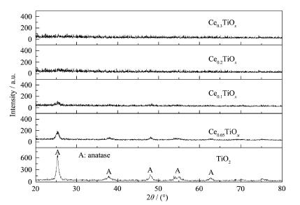
Fig. 2 shows the XRD patterns of Ce-Ti mixed oxides after calcination at 450 ℃. As observed, the dif-fraction peaks at 25.3°, 38.3°, 48.2°, 54.5°, 62.5° were a typical anatase for the pure TiO2 material (PDF No.21-1272). In the presence of Ce, no diffraction peak related to CeO2 crystalline phase was found, indicating that Ce species were well dispersed on the surface of anatase TiO2 existed as amorphous phase[22]. Further-more, the peaks of anatase TiO2 became weaker with the increase of Ce/Ti molar ratio. No obvious diffrac-tion peak was observed for Ce0.2TiOx and Ce0.3TiOx, indi-cating the phase transformation of TiO2 was suppressed and a complete amorphous structure was formed. The possible reason was attributed to the larger ion radii of Ce3+/Ce4+ (RCe3 + =0.103 nm, RCe 4 +=0.092 nm, RTi 4 +=0.065 nm), when the Ce ions replaced the Ti ions to form the Ti-O-Ce species, causing the distortion of TiO2 lattice and thereby hindering the anatase phase transforma-tion[23-26]. Furthermore, the electronegativity of Ti (1.54) was larger than that of Ce (1.12), the strength of Ti-O bond and thermal stability of the mesostructured were enhanced by the partial electron transfer, and thus in-hibited the anatase phase transformation of TiO2 materi-al[27]. Notably, the short-order Ce-O-Ti species has dem-onstrated to be active sites for the SCR, the occurrence of Ce-O-Ti species could be conducive to improve the SCR performance[18].
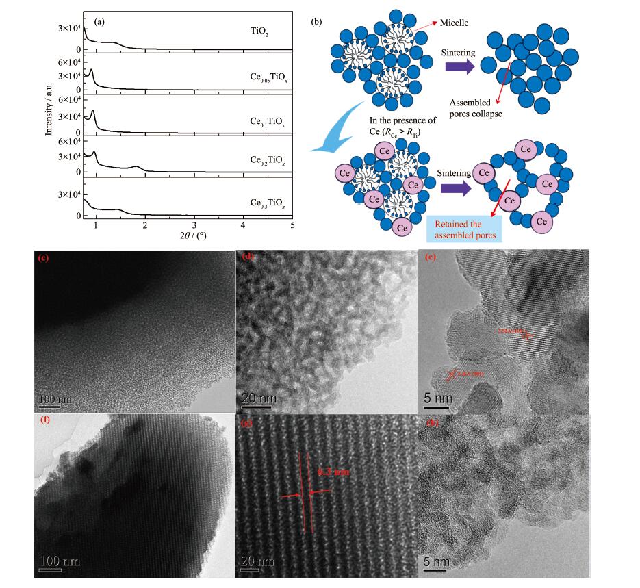
In this study, the ordered mesoporous structure was fabricated via a template assisted sol-gel process. Nevertheless, the assembled ordered pore was prone to collapse with the removal of template and grain growth during the sintering process. To insight into the pore structure, the SAXRD was conducted (Fig. 3a). An obvi-ously diffraction peak for CeaTiOx catalyst was observed and enhanced with the increase in the Ce/Ti molar ratio, except the Ce0.3TiOx, indicating the ordered pore structure well retained. In contrast, pure TiO2 cat-alyst exhibited a weak diffraction peak, manifesting the ordered pore structure collapsed seriously. The possi-ble reason was that the crystal grain growth was suppressed by the presence of the Ce species. Further-more, the large Ce species entered into and consolidated the pore framework, so the thermal stability of ordered pore structure was improved (Fig. 3b). Never-theless, too high a level of Ce doping, Ce0.3TiOx, the continuity of the TiO2 framework can be disturbed and harmed the alignment of mesopores[28]. Further evi-dence for the pore structure of the catalyst is provided in the TEM images (Fig. 3c~h)). As expected, a disor-dered wormlike structure and a high degree of crystalli-zation was observed for pure TiO2 catalyst. In contrast, the Ce0.2TiOx presented highly ordered hexagonal pore structure with a pore size of ~6.3 nm and no nanocrys-tal structure was observed, manifesting the ordered pore structure was stabilized by the inhibition of the grain growth with the presence of Ce.
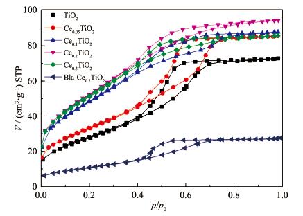
To further explore the microstructure, the porosity and surface area of the catalyst was investigated by the N2 adsorption-desorption isotherms (Fig. 4 and Table 1). All the catalysts showed a type Ⅵ gas adsorption isotherm, which was a typical mesoporous structure. In the presence of Ce species, the assembled ordered pore was well retained, a dramatic increase of the BET (Brunauer-Emmett-Teller) surface area of the CeaTiOx catalysts was observed. With the increase of the Ce amount, the surface area was increased from 103 to 195 m2·g-1, especially the Ce0.2TiOx catalysts with high-ly ordered pore structure delivered the largest surface area. The surface area of Bla-Ce0.2TiOx catalysts with-out template hugely decreased to 40 m2·g-1. Further-more, the pore size of the catalyst was slightly decreased with the increase of the Ce amount because the larger Ce ion entered into the TiO2 pore framework.
 下载:
导出CSV
下载:
导出CSV
| Catalyst | Pore size / nm | BET surface area / (m2·g-1) | Pore volume / (cm3·g-1) | Porosity / % |
| TiO2 | 4.19 | 103 | 0.116 | 30.87 |
| Ce0.05TiOx | 4.55 | 123 | 0.128 | 32.65 |
| Ce0.1TiOx | 3.28 | 179 | 0.124 | 32.45 |
| Ce0.2TiOx | 3.28 | 195 | 0.134 | 33.97 |
| Ce0.3TiOx | 3.34 | 190 | 0.125 | 31.71 |
| Bla-Ce0.2TiOx | 3.71 | 40 | 0.046 | 26.62 |
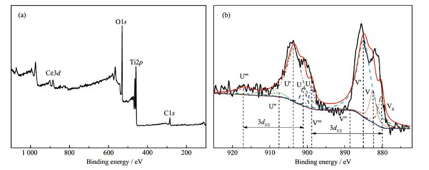
Subsequently, the catalyst was analyzed by XPS to determine its main elements and chemical states (Fig. 5), the detailed atomic fraction of the catalyst is summarized in Table 2. As observed, four elements, namely, Ti, Ce, O and C, were present together on the Cea TiOx surface. With the increase of the Ce content, the content of oxygen slightly was decreased and the content of carbon was increased. For the Ce3d XPS spectrum, it was complicated as a result of the hybrid-ization of the Ce4f with ligand orbitals and partial occu-pation of the 4f orbitals. It was reported that the Ce3d spectra was consisted of two sets of spin-orbital multi-plets, Ce3d5/2 and Ce3d3/2, denoted as V and U, respec-tively. The U‴ (916.7 eV), U″ (907.5 eV), U (901.0 eV), V‴ (898.4 eV), V″ (888.2 eV) and V (882.5 eV), were corresponding to the Ce4+, while the U' (903.5 eV), U0 (898.8 eV), V' (884.9 eV) and V0 (880.3 eV) were cor-responding to the Ce3+ [29]. For the SCR catalyst, the Ce3+ was conducive to the adsorption of NH3 to form NH4+, contributing to the low-temperature SCR activi-ty[30-31]. Based on the fitting calculation of peak area, the Ce0.2 TiOx catalyst delivered the highest Ce3+/Ce4+ ratio, and may delivered desirable low-temperature SCR activity.
 下载:
导出CSV
下载:
导出CSV
| Catalyst | Atomic fraction / % | Atomic ratio of Ce3+ to Ce4+ | |||
| Ti | O | C | Ce | ||
| TiO2 | 21.34 | 74.68 | 3.98 | ||
| Ce0.1TiOx | 21.02 | 72.71 | 4.56 | 1.71 | 2.31 |
| Ce0.2TiOx | 20.76 | 69.05 | 6.27 | 3.98 | 2.40 |
| Ce0.3TiOx | 20.15 | 65.86 | 8.34 | 5.55 | 1.92 |
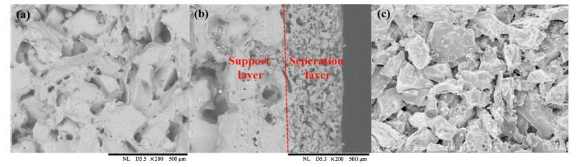
Fig. 6 shows the surface morphology of the catalytic membrane. As observed, the catalytic membrane was consisted of a support layer and a homogeneous and integrated separation layer with a thickness of ~320 μm. The support layer was constructed by a large SiC particles packed, thus the catalyst nanoparticles with small size can be permeated into the pore of the sup-port membrane. It is a prerequisite for the catalytic membrane with a relatively low differential pressure. However, it is inevitable to enlarge the pressure drop with the catalytic particle permeating in the support layer. Fig. 7a shows the pressure drop of the membrane versus the filtration velocity. The pressure drop of the reactor linearly increased with the increasing of the fil-tration velocity. When the filtration velocity increased from 2.6 to 10.6 cm·s-1, the differential pressure was increased from 780 to 3 290 Pa. After loading the cata-lyst, the differential pressure increased with the num-ber of coating times due to the permeation of the cata-lytic particle into the pore of the support membrane. However, the increase degree of the differential pres-sure was not significant, indicating that the prepared catalytic filter could fulfil the criteria for its economic use in the hot gas purification[8].
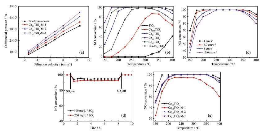
Before the SCR performance of the catalytic mem-brane test, the activity of the unsupported catalysts were evaluated (Fig. 7b~d). Among all of the catalysts, the pure TiO2 presented the lowest SCR activity and the CeaTiOx catalyst exhibited significant enhancement of the SCR activity. Notably, the ordered mesoporous Ce0.2 TiOx exhibited approximately 100% NO conver-sion in a wide temperature range of 175~350 ℃ and demonstrated the highest SCR activity. In contrast, Bla-Ce0.2TiOx catalyst showed an obvious decrease in the SCR activity, suggesting the ordered pore structure with the large surface area and open pore framework was contributing to the SCR performance. Meanwhile, the completed amorphous Ce0.2TiOx could induce a Ce-O-Ti species because of the strong interactions between Ce and Ti, thus the ordered mesoporous Ce0.2TiOx catalyst exhibited a superior SCR catalytic activity[19, 32-33]. Furthermore, the Ce0.3TiOx catalyst pres-ent relative low SCR activity in the low-temperature range was mainly attributed to the collapse of ordered pore structure and the formation of Ce-O-Ce.
Fig. 7c shows the NO conversions over Ce0.2TiOx catalyst under different filtration velocity. The increase of the filtration velocity made the 100% NO conversion in a narrow temperature range. For practical applica-tion, SO2 tolerance was an important factor and the SO2 tolerance over Ce0.2 TiOx catalyst is showed in Fig. 7d. The NO conversion decreased slightly, then reached a steady state, and the NO conversion decreased with the increase of the SO2 concentration. After switching SO2 off, the NO conversion recovered quickly and remained unchanged, manifesting the high sulfur resistance of the Ce0.2TiOx catalyst. It has been demonstrated that the Ce-Ti catalyst, in the presence of SO2, did not re-duce the amount of coordinated NH 3, even promoted the formation of NH4+, and thereby slightly hindered the NO adsorption[19, 34-36]. It can concluded that the Ce 0.2TiOx catalyst with high SCR activity and satisfacto-ry SO 2 tolerance can be a promising catalyst for devel-oping the catalytic membrane.
Herein, the Ce0.2TiOx catalyst was employed to pre-pare the catalytic membrane and the NO conversion of the catalytic membrane was investigated (Fig. 7e). As observed, the Ce0.2TiOx-M-1 presented relative low NO conversion in a temperature range of 150~400 ℃. The Ce 0.2TiOx-M-2 and Ce0.2TiOx-M-3 presented almost simi-lar SCR activity, indicating the Ce0.2TiOx-M-2 obtained the optimum catalyst loading amount, corresponding to a mass fraction of 2.17%. Comparing with the powder catalyst, the catalytic membrane exhibited a slightly low NO conversion due to the inhomogeneous gas velocity in the pore channel of the membrane.
In this study, a template assisted sol-gel method was employed to prepare highly ordered Ce-Ti catalyst with high SCR activity. In the presence of Ce species, the phase transformation of the catalysts were sup-pressed to form an amorphous phase and the assem-bled ordered pore structure were well retained. Mean-while, the BET result showed that the surface area was significantly improved by the additive of Ce species. After the SCR test, the amorphous and ordered pore structure of the Ce 0.2TiOx catalyst presented high SCR activity in a wide temperature range of 175~350 ℃. Subsequently, the Ce0.2TiOx catalyst was loaded on the filter and delivered an almost similar SCR activity with the catalyst powder.
Khalil N M, Hassan E M, Shakdofa M M E, et al. J. Ind. Eng. Chem., 2014, 20:2998-3008 doi: 10.1016/j.jiec.2013.11.034
Hua S B, Tiana H Z, Wang K, et al. Atmos. Environ., 2016, 128:1-9 doi: 10.1016/j.atmosenv.2015.12.056
Beale A M, Gao F, Lezcano-Gonzalez I, et al. Chem. Soc. Rev., 2015, 44:7371-7405 doi: 10.1039/C5CS00108K
Liu F D, Yu Y B, He H. Chem. Commun., 2014, 50:8445-8463 doi: 10.1039/C4CC01098A
Heidenreich S, Haag W, Manfred S. Fuel, 2013, 108:19-23 doi: 10.1016/j.fuel.2011.03.007
Yang B, Huang Q, Chen M D, et al. J. Rare Earths, 2019, 37(3):273-281 doi: 10.1016/j.jre.2018.05.023
Kia J H, Choi J H, Phule A D. Powder Technol., 2018, 327:282-290 doi: 10.1016/j.powtec.2017.12.081
Nacken M. Appl. Catal. B[J]. , 2007, 70: 370-376.
Li X, Li X S, Zhu T, et al. Environ. Sci. Technol., 2018, 52:8578-8587 doi: 10.1021/acs.est.8b00746
Zheng L, Zhou M J, Huang Z W, et al. Environ. Sci. Technol., 2016, 50:11951-11956 doi: 10.1021/acs.est.6b03203
Han L P, Cai S X, Gao M, et al. Chem. Rev., 2019, 119(19):10916-10976 doi: 10.1021/acs.chemrev.9b00202
Zha K W, Feng C, Han L P, et al. Chem. Eng. J., 2020, 381:122764 doi: 10.1016/j.cej.2019.122764
Wang P L, Yan L J, Gu Y D, et al. Environ. Sci. Technol., 2020, 10:6396-6405
Yan L J, Gu Y, Han L P, et al. ACS Appl. Mater. Interfaces, 2019, 11:11507-11517 doi: 10.1021/acsami.9b01291
Li F, Zhang Y B, Xiao D H, et al. ChemCatChem, 2010, 2:1416-1419 doi: 10.1002/cctc.201000179
Gao X, Jiang Y, Fu Y C, et al. Catal. Commun., 2010, 11:465-469 doi: 10.1016/j.catcom.2009.11.024
Maa L, Seoa C Y, Nahataa M, et al. Appl. Catal. B, 2018, 232:246-259 doi: 10.1016/j.apcatb.2018.03.065
Li P, Xin Y, Li Q, et al. Environ. Sci. Technol., 2012, 46:9600-9605 doi: 10.1021/es301661r
Zhang Z P, Chen L Q, Li Z B, et al. Cata. Sci. Technol., 2016, 6:7151-7162 doi: 10.1039/C6CY00475J
Li L L, Sun B, Sun J F, et al. Catal. Commun., 2017, 100:98-102 doi: 10.1016/j.catcom.2017.06.019
Zha K W, Kang L, Feng C, et al. Environ. Sci.:Nano, 2018, 5:1408-1419 doi: 10.1039/C8EN00226F
ZHU Xue-Cheng( 朱学诚). Thesis for the Doctorate of Zhejiang University(浙江大学博士学位论文), 2019.
Yuan S, Sheng Q, Zhang J. Microporous Mesoporous Mater., 2008, 110(2/3):501-507
Periyat P, Baiju K, Mukundan P, et al. J. Sol-Gel Sci. Technol., 2007, 43:299-304 doi: 10.1007/s10971-007-1583-1
Liu C, Tang X H, Mo C H, et al. J. Solid State Chem., 2008, 181:913-919 doi: 10.1016/j.jssc.2008.01.031
Rodriguez-Talaverra R, Vargas S, Aarroyo-Murillo R, et al. J. Mater. Res., 1997, 12(3):439-442
Cao X P, Li D, Jing W, et al. J. Mater. Chem., 2012, 22:15039-15315
Zhang Y, Yuwono A H, Wang J. J. Phys. Chem. C, 2009, 113:21406-21412 doi: 10.1021/jp907901k
Chang L H, Sasirekha N, Chen Y W, et al. Ind. Eng. Chem. Res., 2006, 45(14):4927-4935 doi: 10.1021/ie0514408
Chen L, Li J H, Ge M F. Environ. Sci. Technol., 2010, 44:9590-9596 doi: 10.1021/es102692b
Guan B, Liu H, Zhu L. J. Phys. Chem. C, 2011, 115:12850-12863 doi: 10.1021/jp112283g
Xiao X, Xiong S, Shi Y, et al. J. Phys. Chem. C, 2016, 120:1066-1076 doi: 10.1021/acs.jpcc.5b10577
Yang S J, Guo Y, Chang H Z, et al. Appl. Catal. B, 2013, 137:19-28
Kang L, Han L, He J, et al. Environ Sci Technol., 2019, 53:938-945 doi: 10.1021/acs.est.8b05637
Han L P, Gao M, Feng C, et al. Environ Sci Technol., 2019, 53(10):5946-5956 doi: 10.1021/acs.est.9b01217
Han L P, Gao M, Hasegawa J, et al. Environ Sci Technol., 2019, 53(11):6462-647 doi: 10.1021/acs.est.9b00435

Figure 1 Scheme of the test device for the measurement the performance of the catalytic ceramic filter

Figure 3 (a) SAXRD patterns of the Ce-Ti mixed oxides; (b) Mechanism graph of the Ce stabilizing the ordered mesoporous structure; (c~e) TEM images of TiO2; (f~h) TEM images of Ce0.2TiOx (sintering temperature: 450 ℃)

Figure 5 (a) XPS spectrum of Ce0.2TiO2; (b) High-resolution XPS spectrum of Ce3d (sintering temperature: 450 ℃)

Figure 6 (a) Support layer surface, (b) cross section and (c) seperation layer surface of catalytic membrane

Figure 7 (a) Relationship between differential pressure and filtration velocity; (b) NO conversion of the unsupported catalysts at various temperatures (v=4 cm·s-1); (c) NO conversion of the Ce0.2TiOx catalyst at various velocities; (d) SO2 tolerance of the Ce0.2TiOx catalyst (v=4 cm·s-1, T=250 ℃); (e) NO conversion of the prepared catalytic membrane (v=4 cm·s-1)
Table 1. Microstructure of the catalysts (450 ℃)
| Catalyst | Pore size / nm | BET surface area / (m2·g-1) | Pore volume / (cm3·g-1) | Porosity / % |
| TiO2 | 4.19 | 103 | 0.116 | 30.87 |
| Ce0.05TiOx | 4.55 | 123 | 0.128 | 32.65 |
| Ce0.1TiOx | 3.28 | 179 | 0.124 | 32.45 |
| Ce0.2TiOx | 3.28 | 195 | 0.134 | 33.97 |
| Ce0.3TiOx | 3.34 | 190 | 0.125 | 31.71 |
| Bla-Ce0.2TiOx | 3.71 | 40 | 0.046 | 26.62 |
 下载: 导出CSV
Table 2. Atomic fraction of Ti, O, C and Ce
| Catalyst | Atomic fraction / % | Atomic ratio of Ce3+ to Ce4+ | |||
| Ti | O | C | Ce | ||
| TiO2 | 21.34 | 74.68 | 3.98 | ||
| Ce0.1TiOx | 21.02 | 72.71 | 4.56 | 1.71 | 2.31 |
| Ce0.2TiOx | 20.76 | 69.05 | 6.27 | 3.98 | 2.40 |
| Ce0.3TiOx | 20.15 | 65.86 | 8.34 | 5.55 | 1.92 |
下载: 导出CSV

 扫一扫看文章

扫一扫关注我们