Table 1.
Physical properties of MoS2 and PEP
Citation:
QI Yu-Cong, SHEN Xiao-Quan, LIU Jia-Hao, XIAO Xuan-Zhong, SHEN Qun-Dong. Photo-Thermoelectric Generation in MoS2/Pyroelectric Polymer Nanocomposites for Collection of Near-Infrared Light Energy[J]. Chinese Journal of Inorganic Chemistry,
2019, 35(12): 2364-2372.
doi:
10.11862/CJIC.2019.268

利用光热电效应收集近红外光能的二硫化钼和热释电高分子纳米复合物
摘要:
设计合成了一种基于二硫化钼(MoS2)/热释电聚合物的柔性薄膜光热电纳米发电机(PTENG)。过渡金属硫族化合物作为薄层纳米薄片,可以捕获近红外(NIR)光,并将其转化为热能。同时,热释电聚合物将无机纳米片所收集的热能转化为电能。在近红外辐照下,PTENG可以瞬间产生电压和光电流,且输出长期保持在较高水平。通过光热效应与热释电效应的有效耦合,该体系具有较高的热电转换系数。我们还通过理论模拟分析了MoS2在聚合物纳米复合材料中的作用。MoS2的存在显著提高了热释电聚合物薄膜的温度变化率,提高了器件的光电响应。
English
Photo-Thermoelectric Generation in MoS2/Pyroelectric Polymer Nanocomposites for Collection of Near-Infrared Light Energy
Abstract:
We design a photo-thermoelectric nanogenerator (PTENG) based on a flexible film of molybdenum disulfide (MoS2) dispersed in a pyroelectric polymer. The transition-metal dichalcogenide as thin-layered nanosheets can harvest the incident near-infrared (NIR) light and convert it into thermal energy. The pyroelectric polymer subsequently transduced the thermal energy collected by the inorganic nanosheets into electric energy. Under NIR irradiation, the PTENG can generate voltage and photocurrent instantly, and the output kept at high level for a long time. High thermoelectric conversion coefficient was obtained, which arised from efficient coupling between photothermal and pyroelectric effects. Theoretical simulation distinguished the contribution of MoS2 in the polymer nanocomposite. MoS2 significantly increased the temperature change rate in pyroelectric polymer films, leading to enhanced photoelectric response in the device.
-
0. Introduction
Molybdenum disulfide (MoS2) as one of the transition-metal dichalcogenides and two-dimensional layer materials has recently shown promising potential for modern electronics and optoelectronics. Due to high carrier mobility and low power consumption, such semiconducting material could be fabricated into field-effect transistors with sub-5-nanometer gate length in atomically thin integrated circuitry[1-4]. MoS2 presents two-dimensional Ising superconductivity, as well as tunable resistance states in multi-terminal memtransis-tors for data storage and neuromorphic computing purpose[5-6]. Optoelectronic performance of MoS2 is also attractive, which enable it for building block of electroluminescence device and high-sensitive picosecond-responsive photodetectors in the visible to near-infrared wavelength rang[7-12].
Energy collection is of vital importance for wearable or implantable electronics. Single-layer MoS2 with nanoscale pore has been utilized as power generator based on osmotic pressure of electrolyte solution[13], thus has the capability of operating in the physiological environment. Single-layer MoS2 has strong piezoelectricity, i.e., generation electric energy in response to applied mechanical energy that is readily available during our physical movement. A power density of 2 mW·m-2 and a 5% energy conversion efficiency is found when the MoS2 sheets undergo cyclic bending[14]. Thermoelectric power generators by single-layer or few-layer MoS2 are also demons- trated[15-16]. It provides a way of utilizing thermal energy, which is abundant in our living environment. Most recently, MoS2 nanosheet as narrow bandgap semiconductor can efficiently convert near-infrared (NIR) light energy into thermal energy, and is promising photothermal materials for cancer therapy. The MoS2 sheet has a photothermal conversion efficiency up to 60%[17-19].
For portable or implantable electronics, polymer materials that are flexible in nature and biocompatible with biological tissue is attracting great attention. Poly(vinylidene fluoride) (PVDF) and its copolymers are versatile functional materials that have both piezoelectricity and pyroelectricity[20]. These properties make them exporter in harvesting electric energy from physiological environment[21-22]. Here we design a photo-thermoelectric nanogenerator (PTENG) based on a flexible film of the MoS2 sheets dispersed in a pyroelectric polymer (PEP), P(VDF-TrFE-CFE), i.e. a ternary copolymer of vinylidene fluoride (VDF), trifluoroethylene (TrFE), and chlorofluoroethylene (CFE). The polymer has weak absorption in the visible and NIR regions, thereby preventing effective conversion of light energy into thermal energy. The MoS2 thin-layered nanosheets in the polymer matrix can harvest the incident NIR light and convert it into thermal energy. The pyroelectric polymer subsequently can transduce the thermal energy collected by the inorganic nanosheets into electric energy.
1. Materials and methods
1.1 Materials
P(VDF-TrFE-CFE), i.e. a ternary copolymer of VDF, TrFE, and CFE with molar ratio of 62.6:29.4:8, was purchased from Arkema Piezotech. Molybdenum(Ⅳ) sulfide was provided by Energy Chemical. Indium tin oxide (ITO)-coated glass with sheet resistance less than 7 Ω was obtained from Zhuhai Kaivo Optoelec-tronic Technology. The glass was cleaned ultrasoni-cally in acetone, ethanol, and isopropyl alcohol for 10 min sequentially. N, N-dimethylformamide (DMF) was analytically pure and obtained from Sinopharm Chemical Reagent. Other reagents were used as received without further treatment.
1.2 Methods
1.2.1 Preparation of photo-responsive nanocomposite film
The P(VDF-TrFE-CFE) powder was dissolved in DMF (40 mg·mL-1) by stirring magnetically at room temperature overnight. The MoS2 powder with different mass fractions (10% and 25%(w/w)) was mixed with the P(VDF-TrFE-CFE) solutions by a magnetic stirrer followed by ultrasonication. Then, the mixed solution was cast onto a pre-cleaned ITO-coated glass. After removal of the solvent at 80 ℃ overnight, the MoS2/PEP nanocomposite films were annealed at 120 ℃ for 4 hours and naturally cooled to room temperature.
The absorption spectroscopy of the PEP and MoS2/PEP films was measured by using Mapada UV-1800PC spectrophotometer. The particle size distribu-tion measurement was performed on a Brookhaven Nano Brook Omni dynamic light scattering instrument with a red laser beam at 640 nm. The sample was dissolved in DMF. The transmission electron micros-copy (TEM) photograph of the MoS2/PEP nanocom-posite was obtained by a JEOL JEM-2100 transmiss-ion electron microscope with the accelerating voltage of 200 kV. The sample was prepared by dropping the dispersion onto a carbon film supported by a copper mesh, followed by naturally drying in the air. The X-ray diffraction pattern of the pyroelectric polymer and MoS2/PEP nanocomposite was collected by Bruker D8 Advance X-ray diffractometer using Cu Kα radiation (λ=0.154 nm) with operating voltage of 40 kV and current of 40 mA. The scan range was 10°~65°. The film was fabricated by solution-cast on a glass slide, dried at 80 ℃, and then thermal annealed at 120 ℃ for 4 hours.
1.2.2 Photothermal measurement and theoretical simulation
The photothermal response of the MoS2/PEP nanocomposite films was collected by a Fotric 226S thermal infrared imager. LWIRL-915-1W-F near infrared laser (Beijing Laserwave Optoelectronics) was used to irradiate the sample. The laser beam oriented perpendicularly and had a wavelength of 915 nm. The temperature change was recorded 30 times per second.
For electrical measurement, the MoS2/PEP nano-composite film was cast on ITO glass with electrode area of 2.25 cm2. Then, silver electrode with area of 0.8 cm2 was applied to top side of the film by physical vapor deposition using PVD75 PRO Line EB (Kurt J. Lesker Co.) thin film deposition system. The data were captured by using an electrochemical workstation (CHI 800B, CH Instruments, Inc.). The infrared light was incident from the ITO side. Dependence of the photocurrents on the incident power density was obtained with fixed irradiation time of 10 s for MoS2(10%)/PEP and 20 s for MoS2(25%)/PEP.
COMSOL multiphysics software was utilized to theoretically study photothermal effect and spatial distribution of the temperature change rate, which employed finite element method (FEM) to analyze heat absorption and temperature increase. The parameter of MoS2 and the pyroelectric polymer for simulation was listed in Table 1. The length, width, and thickness of the film was 100, 100, and 40 μm, respectively. The incident light power density was 124 mW·cm-2 with irradiation time 10 s. The real part of the refractive index was 1.4, and the imaginary part was 0.1.
Table 1
 下载:
导出CSV
下载:
导出CSV
2. Results and discussion
2.1 MoS2/PEP nanocomposite for light harvesting
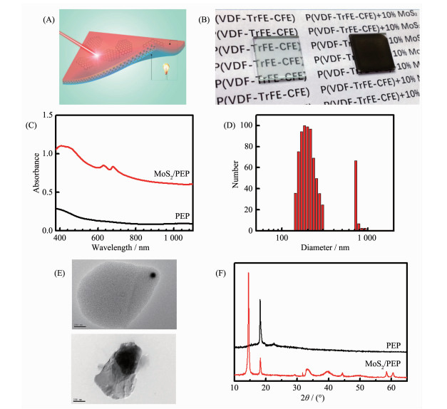
We prepared the light-harvesting polymer film by dispersion of inorganic MoS2 sheet into P(VDF-TrFE-CFE) polymer (Fig. 1A). The MoS2 sheet has high photothermal conversion efficiency. P(VDF-TrFE-CFE) is one of the pyroelectric materials that change their electric polarization in response to the ambient temperature change, and then generate temporary voltage or electric current when connected to an external circuit. Thus, the pyroelectric polymer (PEP) can transduce the thermal energy collected by the MoS2 sheet into electric energy. The polymer can be readily available as optical transparent thin film with large area and has low thermal conductivity.
Figure 1
 Figure 1. MoS2/PEP nanocomposite for light harvesting: (A) Structure and (B) photograph of the 10%MoS2/PEP film, where the MoS2 sheet is photothermal and PEP film is thermoelectric; (C) Absorbance profiles of the PEP and 10%MoS2/PEP films in the visible and NIR regions; (D) Size distribution of the MoS2 sheet dispersion with PEP in DMF solution; (E) TEM images of the MoS2 sheets in the MoS2/PEP nanocomposite; (F) X-ray diffraction patterns of the PEP and 25%MoS2/PEP films
The MoS2 sheet is evenly dispersed in the polymer matrix, resulting in a black opaque film (Fig. 1B). The MoS2/PEP nanocomposite film absorbed light over a wide range, i.e. from 380 to 1 100 nm (Fig. 1C). Thus, it can efficiently collect light energy covering a large part of the solar spectrum. For comparison, the PEP film presented rather weak and featureless absorption curve extending to red and NIR region. The peak with wavelength of 410 nm was from direct electron transition through bandgap; and other two peaks at 630 and 680 nm arised from exciton transition[26]. All of them are typical for MoS2. For the thin film of the nanocomposite, the MoS2 sheet led to remarkably enhanced light absorption, which reached 80%~92% in the visible range and 75%~80% in the NIR region.
The dispersion of the MoS2/PEP has one major component with particle size of 150~300 nm and other minor component with size 700~900 nm when measured by dynamic light scattering (Fig. 1D). The transmission electron microscope (TEM) observation shows that the small MoS2 particle was thin-layer nanosheet, while the large one composes of highly corrugated and stacked sheet (Fig. 1E). The MoS2 nanosheet was thereby arising from ultrasonication-assisted exfoliation from the large sheet with weak interlayer forces. Fig. 1F shows the X-ray diffraction pattern of the MoS2/PEP nanocomposite film. The narrow peak at 18.2° (crystal lattice parameter of 0.487 nm) came from (110) and (200) reflection of PEP. The strong peak at 14.5° was assigned to (002) reflection of the MoS2[27]. Other peaks above 30o were related to the diffraction from high-order planes of MoS2.
2.2 Photothermal properties
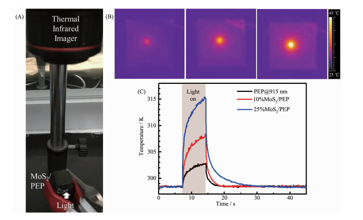
The MoS2 sheets show high absorption of the visible and near infrared light. We investigated the MoS2 mediated light-to-heat conversion in PEP film (Fig. 2A). After irradiation by 915 nm light, IR thermal image of the PEP film shows the heat signal almost identical to the background, indicating its weak photothermal conversion ability. In contrast, the MoS2 sheet in the polymer could efficiently convert the light energy into local heat (Fig. 2B). Photothermal capacity of the MoS2 was evaluated by temperature change. When irrdiated by 915 nm light for 7 s, the temperature of PEP film with 10%(w/w) of MoS2 quickly rose by 10 ℃ (Fig. 2C). During the same irradiation time, the temperature of the nanocomposite film with 25%(w/w) of MoS2 increased by 17 ℃, while the PEP film only experienced a 4 ℃ increase in temperature. It is intriguing that the photothermal effect is dependent on light wavelength. When irradiated by red light (660 nm), the maximum photothermal temperature of the MoS2(10%)/PEP nanocomposite film was 15 ℃, 10-fold higher than that of the PEP film. For comparison, at 915 nm light irradiation, the maximum photothermal temperature increased only 2 times when the MoS2 sheet was incorporated into PEP films. It suggests that photothermal conversion efficiency of the nano-composite relies on both on electron absorption and phonon transportation of the MoS2 sheet[28].
Figure 2
 Figure 2. Photothermal properties: (A) Infrared thermal imaging experimental setup; (B) IR thermal images of the PEP, 10%MoS2/PEP, and 25%MoS2/PEP films under 915 nm laser irradiation with a power density of 124 mW·cm-2; (C) Temperature profiles of PEP and MoS2/PEP nanocomposite films under illumination with a power density of 124 mW·cm-2
2.3 Photo-thermoelectric nanogenerator (PTENG)
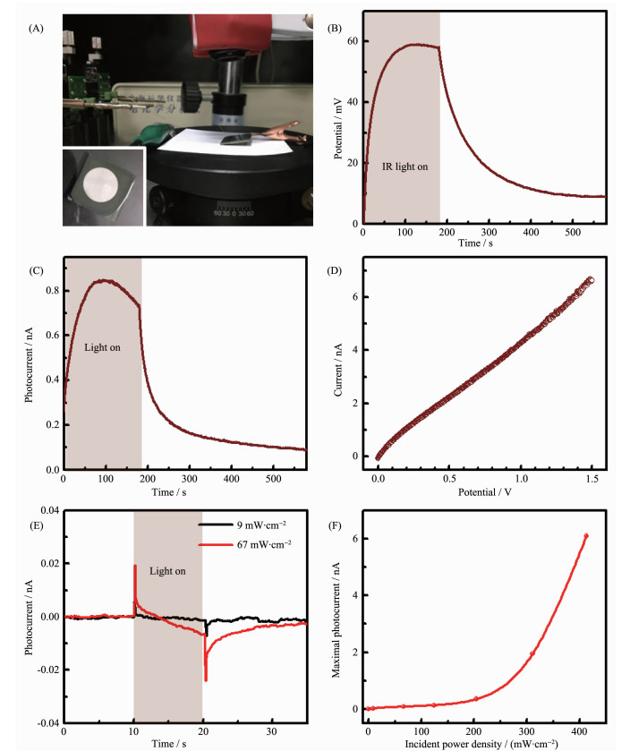
We fabricated the PTENG based on the MoS2/PEP film by solution-cast on ITO glass, followed by deposition of silver electrode on the film surface. The device is connected to the probe station by copper wires for electrical measurement (Fig. 3A). When the infrared light irradiated on the surface of the nanogenerator, a voltage was instantly created across the 10%MoS2/PEP film sandwiched between two electrodes, and increased rapidly within 10 s and gradually reached saturation after 120 s (Fig. 3B). The peak output voltage could reach 59 millivolts under light irradiation. The open-circuit voltage of the device decays after removing the incident light. By fitting the voltage response curve under infrared irradiation or removal of light using a single exponential function, typical rise and decay time (τ) were found to be 22 and 68 s, respectively. The decay time of MoS2 phototransistors is 9 s[29], while it takes much time for the response of the PTENG device. It suggests that pyroelectric effect, instead of electron-hole pair generation, is responsible for the observed photo-electric response.
Figure 3
 Figure 3. PTENG: (A) Experimental setup and the device under infrared light irradiation (Inset: the nanocomposite film with electrode); (B) Open-circuit voltage and (C) short-circuit photocurrent of the PTENG based on the 10%MoS2/PEP film (Incident power density was 124 mW·cm-2); (D) I-V characteristics of the device; (E) Photocurrent response of the device based on the 10%MoS2/PEP film (Irradiation time was 10 s); (F) Dependence of the maximal photocurrent of the device based on the 25%MoS2/PEP on light power density (Irradiation time was 20 s)
Considering the temperature rise (10.1 K) in the 10%MoS2/PEP film under infrared light illumination, the thermoelectric coefficient was estimated to be 5.8 mV·K-1. The Seebeck coefficient, which measures induced voltage in response to a temperature gradient across the hot and cold terminal, of the MoS2/polyurethane film is found to be 0.042 mV·K-1 [16]. Other flexible thermoelectric nanogenerators have Seebeck coefficient of 0.1~0.3 mV[16, 30-31]. This result indicates that the coupling between photothermal and pyroelectric effects plays a significant role in increasing the output voltage of the nanogenerator.
The time-dependence short-circuit current had the trend as that of output voltage (Fig. 3C). By fitting the photocurrent curves, the characteristic time of rising and falling part were 26 and 30 s, respectively. The current-voltage curve of the PTENG displayed an ohm behavior (Fig. 3D). It is noteworthy that, in the case of short irradiation time, the photocurrent increased rapidly, and then decreased in a very short time (Fig. 3E). The photocurrent acquired at different incident power density is shown in Fig. 3F. Nearly linear response is found at power density lower than 150 mW·cm-2. Under high illumination intensity, the photocurrent showed a steep increase with the increase of power density. For 25%MoS2/PEP film, the maximal photocurrent reached 6.1 nA at light power density of 400 mW·cm-2. Therefore, the output of the nanocomposite is highly correlate with the light absorption of the MoS2 sheet.
2.4 Theoretical study on photo-thermoelectric effect
Then, we investigated the mechainsm that determined the promising photoelectric behavior of the PTENG. The temperature change rate of the 10%MoS2/PEP nanocomposite film showed dramatic increase or decrease under infrared irradiation or removal light source (Fig. 4A). Correspondingly, the photocurrent of the device changed instantly when the light was switched on and off. According to the theory, the pyroelectric current (I) can be expressed as: I=pAdT/dt, where p is the pyroelectric coefficient; A is the surface area of the sample; dT/dt is the temperature change rate of the material[32]. Since both p and A remained unchanged in our case, the short-circuit current was proportional to dT/dt. In other words, the change of photocurrent should have the same trend as the change rate of temperature, which is in good agreement with the experimental results. Thus, the coupling between the photothermal and pyroelectric effect is critical for the observed device behavior.
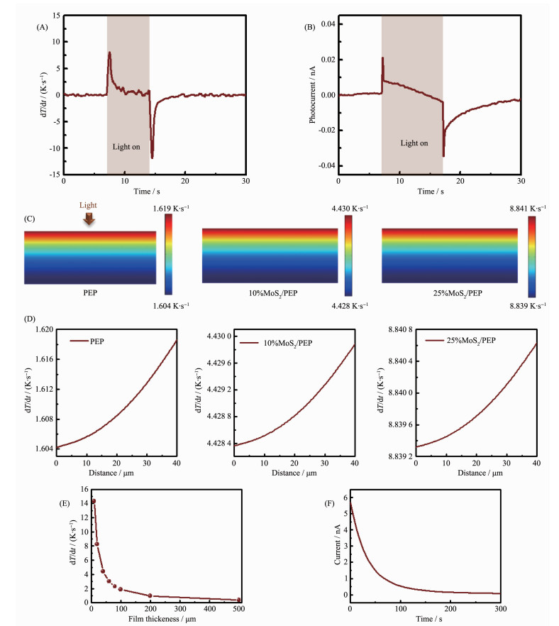
Figure 4
 Figure 4. (A) Temperature change rate of the 10%MoS2/PEP film and (B) photocurrent of the PTENG (Incident power density was 124 mW·cm-2; Theoretical simulated (C) distribution of temperature change rate within the films and (D) along vertical direction of the film (Film thickness was 40 μm); (E) Maximum temperature change rate of the 10%MoS2/PEP film with different thickness; (F) Shirt-circuit current of the device during natural cooling from 50 ℃ to room temperature (22 ℃)
It is worthwhile to distinguish the contribution of the photothermal MoS2 sheets in the PEP film. It is difficult to measure the temperature distribution within the thin films of pyroelectric polymer and its nanocomposites. Alternatively, we used theoretical simulation by finite element method to afford the spatial distribution of temperature change rate (Fig. 4D). The physical parameters of MoS2 and PEP are shown in Table 1.
When the infrared light illuminated from the top of the film, the temperature gradient quickly built up. The maximal temperature change rate was found on the top side due to poor thermal conductivity of the PEP film. For the MoS2/PEP nanocomposite films, the rate of temperature change increased significantly. The calculated temperature change rate of the 10%MoS2/PEP film was very close to the observed value. It intuitively supports the origination of high photothermal effect brought about by the MoS2 sheets. The simulated result also showed that maximum temperature change rate of the 10%MoS2/PEP nanocomposite decreased with the increase of the film thickness (Fig. 4E). We also find that the electrical current change of the device during natural cooling to room temperature (Fig. 4F) resembled photoelectric response curve when the light was turned off. This suggests that the photoelectric response is indeed closely related with the thermal effect.
3. Conclusions
In summary, we fabricated a photothermal pyro-electric nanogenerator based on the MoS2 and a pyroelectric polymer. The transition-metal dichalcog-enide as thin layered nanosheet has high efficiency on conversion of the NIR light energy into the thermal energy. The pyroelectric polymer subsequently transduces the thermal energy collected by the inorganic nanosheet into electric energy. Under light irradiation, the device can generate voltage and photocurrent instantly, and the output maintains high level for a long time. High thermoelectric coefficient is found, which is ascribed to efficient coupling between photothermal and pyroelectric effects. Theoretical simulation distinguishes the contribution of the photothermal MoS2 in the nanocomposite. Our research provides strategy for developing novel photoelectric devices and nanogenerators for wear and implantable electronics.
Acknowledgements: This work was supported by the National Key Research and Development Program of China (Grant No.2017YFA0701301), National Natural Science Foundation of China (Grant No.21875101), and Natural Science Foundation of Jiangsu Province (Grant No.BK20171336). -
-
[1]
Kang K, Xie S, Huang L, et al. Nature, 2015, 520(7549):656-660 doi: 10.1038/nature14417
-
[2]
Sarkar D, Xie X, Liu W, et al. Nature, 2015, 526(7571):91-95 doi: 10.1038/nature15387
-
[3]
Chee S S, Seo D, Kim H, et al. Adv. Mater., 2019, 31(2):1804422 doi: 10.1002/adma.201804422
-
[4]
Ko C, Lee Y, Chen Y B, et al. Adv. Mater., 2016, 28(15):2923-2930 doi: 10.1002/adma.201504779
-
[5]
Lu J M, Zheliuk O, Leermakers I, et al. Science, 2015, 350(6266):1353-1357 doi: 10.1126/science.aab2277
-
[6]
Sangwan V K, Lee H S, Bergeron H, et al. Nature, 2018, 554(7693):500-504 doi: 10.1038/nature25747
-
[7]
Li D H, Cheng R, Zhou H L, et al. Nat. Commun., 2015, 6:7509 doi: 10.1038/ncomms8509
-
[8]
Cheng R, Li D H, Zhou H L, et al. Nano Lett., 2014, 14(10):5590-5597 doi: 10.1021/nl502075n
-
[9]
Eginligil M, Cao B C, Wang Z L, et al. Nat. Commun., 2015, 6:7636 doi: 10.1038/ncomms8636
-
[10]
Lien D H, Uddin S Z, Yeh M, et al. Science, 2019, 364(6439):468-471 doi: 10.1126/science.aaw8053
-
[11]
Wang H N, Zhang C J, Chan W M, et al. Nat. Commun., 2015, 6:8831 doi: 10.1038/ncomms9831
-
[12]
Wu J Y, Chun Y T, Li S P, et al. Adv. Mater., 2018, 30(7):1705880 doi: 10.1002/adma.201705880
-
[13]
Feng J D, Graf M, Liu K, et al. Nature, 2016, 536(7615):197-200 doi: 10.1038/nature18593
-
[14]
Wu W Z, Wang L, Li Y L, et al. Nature, 2014, 514(7523):470-474 doi: 10.1038/nature13792
-
[15]
Arab A, Li Q. Sci. Rep., 2015, 5:13706 doi: 10.1038/srep13706
-
[16]
He M, Lin Y J, Chiu C M, et al. Nano Energy, 2018, 49:588-595 doi: 10.1016/j.nanoen.2018.04.072
-
[17]
Chou S S, Kaehr B, Kim J, et al. Angew. Chem. Int. Ed., 2013, 52(15):4160-4164 doi: 10.1002/anie.201209229
-
[18]
Fu C H, Tan L F, Ren X L, et al. Chem. Commun., 2018, 54(99):13989-13992 doi: 10.1039/C8CC08279K
-
[19]
Yin W Y, Yu J, Lv F T, et al. ACS Nano, 2016, 10(12):11000-11011 doi: 10.1021/acsnano.6b05810
-
[20]
Chen X, Han X, Shen Q D. Adv. Electron. Mater., 2017, 3(5):1600460 doi: 10.1002/aelm.201600460
-
[21]
Han X, Chen X, Tang X, et al. Adv. Funct. Mater., 2016, 26(21):3640-3648 doi: 10.1002/adfm.201600008
-
[22]
Chen X, Pan S, Feng P J, et al. Adv. Mater., 2016, 28(48):10684-10691 doi: 10.1002/adma.201603618
-
[23]
Jo I, Pettes M T, Ou E, et al. Appl. Phys. Lett., 2014, 104(20):201902 doi: 10.1063/1.4876965
-
[24]
Iguchi C Y, dos Santos W N, Gregorio R. Polym. Test., 2007, 26(6):788-792 doi: 10.1016/j.polymertesting.2007.04.009
-
[25]
Levesque M, Cote M, Lelievre S, et al. Proc. SPIE, Infrared Technology XX, 1994, 2269:124-130 doi: 10.1117/12.188629
-
[26]
Benavente E, Santa Ana M A, Mendizábal F, et al. Coord. Chem. Rev., 2002, 224(1/2):87-109 http://www.sciencedirect.com/science/article/pii/S0010854501003927
-
[27]
Visic B, Dominko R, Gunde M K, et al. Nanoscale Res. Lett., 2011, 6:593 doi: 10.1186/1556-276X-6-593
-
[28]
Tan S J R, Sarkar S, Zhao X, et al. ACS Nano, 2018, 12(5):5051-5058 doi: 10.1021/acsnano.8b02649
-
[29]
Lopez-Sanchez O, Lembke D, Kayci M, et al. Nat. Nanotechnol., 2013, 8(7):497-501 doi: 10.1038/nnano.2013.100
-
[30]
Jung Y S, Jeong D H, Kang S B, et al. Nano Energy, 2017, 40:663-672 doi: 10.1016/j.nanoen.2017.08.061
-
[31]
Yang Y, Lin Z H, Hou T, et al. Nano Res., 2012, 5(12):888-895 doi: 10.1007/s12274-012-0272-8
-
[32]
Whatmore R W. Rep. Prog. Phys., 1986, 49(12):1335-1386 doi: 10.1088/0034-4885/49/12/002
-
[1]
-
Figure 1 MoS2/PEP nanocomposite for light harvesting: (A) Structure and (B) photograph of the 10%MoS2/PEP film, where the MoS2 sheet is photothermal and PEP film is thermoelectric; (C) Absorbance profiles of the PEP and 10%MoS2/PEP films in the visible and NIR regions; (D) Size distribution of the MoS2 sheet dispersion with PEP in DMF solution; (E) TEM images of the MoS2 sheets in the MoS2/PEP nanocomposite; (F) X-ray diffraction patterns of the PEP and 25%MoS2/PEP films
Figure 2 Photothermal properties: (A) Infrared thermal imaging experimental setup; (B) IR thermal images of the PEP, 10%MoS2/PEP, and 25%MoS2/PEP films under 915 nm laser irradiation with a power density of 124 mW·cm-2; (C) Temperature profiles of PEP and MoS2/PEP nanocomposite films under illumination with a power density of 124 mW·cm-2
Figure 3 PTENG: (A) Experimental setup and the device under infrared light irradiation (Inset: the nanocomposite film with electrode); (B) Open-circuit voltage and (C) short-circuit photocurrent of the PTENG based on the 10%MoS2/PEP film (Incident power density was 124 mW·cm-2); (D) I-V characteristics of the device; (E) Photocurrent response of the device based on the 10%MoS2/PEP film (Irradiation time was 10 s); (F) Dependence of the maximal photocurrent of the device based on the 25%MoS2/PEP on light power density (Irradiation time was 20 s)
Figure 4 (A) Temperature change rate of the 10%MoS2/PEP film and (B) photocurrent of the PTENG (Incident power density was 124 mW·cm-2; Theoretical simulated (C) distribution of temperature change rate within the films and (D) along vertical direction of the film (Film thickness was 40 μm); (E) Maximum temperature change rate of the 10%MoS2/PEP film with different thickness; (F) Shirt-circuit current of the device during natural cooling from 50 ℃ to room temperature (22 ℃)
-


 下载:
下载:


 扫一扫看文章
计量
- PDF下载量: 12
- 文章访问数: 955
- HTML全文浏览量: 202
