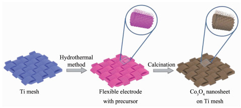
Figure 1.
Typical fabrication process of flexible layered Co3O4 nanosheet electrodes
Layered Co3O4/Ti Nanosheet Flexible Electrode with Low Transfer Resistance for Supercapacitor
Dan-Dan HAN , Yuan ZHAO , Ye SHEN , Yuan-Sheng DING , Zhen-Yu CHENG , Xiao-Yan JING , Xue-Yi ZHANG

The urgent demand for wearable electronic devices has attracted increasing interests in flexible and lightweight energy storage devices[1-2]. Supercapacitors emerge from other candidates because of the high power density, charge/discharge rate and efficient cycle stability[3-4]. In accordance with the energy storage mechanisms, supercapacitors can be divided into electrochemical double-layer capacitors (EDLCs) which store energy physically at the electrodes surface within electrolyte and pseudocapacitors which store energies by fast redox reactions[5-7]. Conventional supercapacitors are usually based on activated carbon electrodes which have high power density, long cycle life, and rapid charging/discharging rate[8]. However, among the series of pseudocapacitors electrode materials for supercapacitor applications, transition metal oxides are widely studied due to variable oxidation states of metal ions which facilitate redox transitions and higher charge storage within the potential range of water decomposition[9-10]. Generally, the metal oxides with the following characteristics could be a super candidate as supercapacitor electrode materials[11-16]: (1) Metal may coexist in two or more oxidation states without phase transition in a continuous range and without modification of an irreversible three-dimensional structure; (2) The transition metal oxide should be electronically conductive; (3) The protons can be freely released and inserted into the oxidation lattice during the redox. Co3O4 is considered to be one of the better alternate materials because of their rich oxidation states, low cost, high theoretical specific capacitances, and environment friendly nature. Since charge storage is directly related to surface properties, controlling the surface morphology of electrode materials has a great influence on their electrochemical properties. Although various structures have been demonstrated to be quite feasible for high performance and stable electrodes, the design of the layered structure plays a more critical role for high performance supercapacitor applications, because layered structures can be flake-off resistant and better tolerant to high rate redox reactions[17-21].
As a method to improve the conventional process, the in situ growth of active materials on a flexible substrate has attracted extensive attention, because they can be used as the finished electrode directly[22-23]. As expected, this method improves the performance of the electrodes. Some progress has been made in foam, fiber and paper substrate. The general method of fabricating 3D arrays structures involves chemical preparation of Co3O4 and assembly of various architectures[24-26]. These processes, however, always bring in some defects and impurities resulting in poor conductivity.
Based on the survey above, a convenient and scalable hydrothermal based approach to deposit layered Co3O4 nanosheets directly grown on flexible titanium mesh substrate as a binder-free electrode for low ion-transfer resistance has been designed. The layered Co3O4 was composed of uniform rectangular and micrometer length 2D flakes. These highly layered Co3O4 materials with nanostructures were functioned directly as supercapacitors electrodes without further treatment delivered lower ion-transfer resistance and good cycle stability.
All reagents were purchased from the Aladdin Chemical Reagent Company and were used without further purification. Generally, 2.5 mmol Co(NO3)2 and 12.5 mmol CO(NH2)2 were dissolved in 30 mL distilled water with constant stirring to obtain a settled solution. Then, the pre-treated titanium mesh (1 cm×1 cm) and the settled solution were transferred into a Teflon-lined stainless steel autoclave. The stainless steel autoclave was maintained at 95 ℃ for 8 h, and then cooled to room temperature. Finally, the samples were treated at 350 ℃ for about 3.5 h.
The crystalline information of the as-prepared products was analyzed by X-ray diffraction (XRD, DX-2700 Dandong Haoyuan, Cu Kα, λ=0.154 05 nm, operating voltage=40 V, operating current=30 mA, the scan rate=0.33°·s-1, 2θ=30°~85°). The structural investigation of the layered Co3O4 samples were deter-mined using a scanning electron microscope (SEM, JSM-6480A, Japan Electronics, operating voltage=20 V) and high-resolution transmission electron micros-copy (HRTEM, FEI, Tecnai G2 F20, 120 kV).
The electrochemical tests were performed by a three-electrode system with a 2.0 mol·L-1 KOH elec-trolyte. Pt foils and a saturated calomel electrode (SCE) were used as the counter electrode and the reference electrode. The loaded weight of the active materials was controlled to be approximately 3.1 mg·cm-2.
The specific capacitance (Cs) of the Co3O4 sample was calculated from the cyclic voltammetry (CV) curves according to Equation (1)[10, 27]:
|
$ {C_{\rm{S}}} = (\int {I{\rm{dV}}} )/(\mathit{vmV}) $ |
(1) |
where I is the current (A), m is the mass of active material (g), v and dV are the potential scan rate and the differential of potential.
The Cs was also calculated by discharge curves[28-29]:
|
$ {C_{\rm{S}}} = I\Delta \mathit{t}/(\mathit{m}\Delta \mathit{V}) $ |
(2) |
Where I is applied current density (A), m is the mass of the sample (g), Δt is discharge time (s), and ΔV is operating potential (V).
Fig. 1 illustrates the fabrication procedure of the layered Co3O4 nanosheets on Ti mesh. Firstly, urea broken down into HCO3-, and then the major precursor of Co2(OH)2CO3 were prepared by the reaction of Co2+ with CO32- and OH- in the mixed solution. The purple precursor on Ti mesh appeared after the reactions and rinsed with distilled water several times. After calcinations at 350 ℃ for 3.5 h, layered Co3O4 electrode was obtained. The advantage of the integrative Co3O4 directly grown on flexible substrate is that it can avoid the traditional volume loss caused by the process of mixing active materials with conductive additives and polymer binder[30-31].
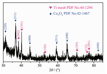
The XRD pattern of the layered Co3O4 nanosheets on Ti mesh is shown in Fig. 2. Except for some diffraction peaks originating from Ti mesh, the well-defined peaks of The peak of Co3O4 nanosheet at 31.3°, 36.9°, 44.8°, 59.4°, 65.2° and 82.6° could be indexed to (220), (311), (400), (511), (440) and (444) plane of the layered Co3O4 crystalline, respectively, which is in accord with the standard XRD pattern of cubic Co3O4 (PDF No.42-1467). No other crystalline phases could be detected, suggesting that the high purity of the obtained Co3O4 nanosheet.
The morphologies of the layered Co3O4 nanosheets on Ti mesh were investigated by SEM. It was clear that Co precursor could be grown uniformly at large scale on skeletons of Ti mesh (Fig. 3). The sample showed the layered morphology with well-arranged 2D microsheets. A detailed observation revealed that the bunches of Co3O4 were vertically and regularly distributed but leaving a highly open interspace which endowed fast transport of the electrolyte. These nanosheets had an edge length of 2~3 μm and a uniform thickness of less than 20 nm.
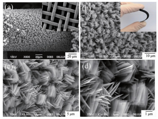
Inset of (a) and (b) were the low resolution SEM images of Co3O4 and the Ti mesh substrate respectively
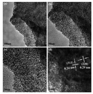
The detailed structure of the single Co3O4 nanosheets was further investigated by TEM, as shown in Fig. 4. It can be seen that Co3O4 nanosheet possessed the abundant pores on its surface, which could be attributed to the gas ejection during the themal transformation from precusor to Co3O4 nanosheets. The nanosheet was composed of numerous interconnected nanoparticles with diameters of 5~10 nm, and showed a mesoporous structure with a pore size of 2~5 nm. Accordingly, the electrolyte can easily pass in and out of the porous structure and transfer between the layers, forming a shorter diffusion path. The high-resolution TEM (HRTEM) image in Fig. 4d revealed the inter-planar spacing of ~0.24 and ~0.29 nm, corresponding to the (311) and (220) plane of Co3O4 given in the standard files. Moreover, the SEM images further proved the flexible nature of the Ti mesh substrate, as shown in Fig. 3(b).
In order to evaluate the electrochemical characteristics of the layered Co3O4 samples, the electrochemical measurements were carried out using a three-electrode system in a 2 mol·L-1 KOH solution.
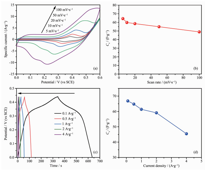
Fig. 5a shows the CV curves of the layered Co3O4 electrode at different scan rates of 5~100 mV·s-1. One pair of redox peaks at various scan rates was clearly observed. Well-fined redox peaks were clearly displayed in all the curves, suggesting the capacitive characteristics of Faradic redox reaction in the electrodes. The possible redox reactions might be described as follows[32]:
|
$ \text{C}{{\text{o}}_{\text{3}}}{{\text{O}}_{\text{4}}}\text{+O}{{\text{H}}^{\text{-}}}\text{+}{{\text{H}}_{\text{2}}}\text{O}\rightleftharpoons \text{3CoOOH+}{{\text{e}}^{\text{-}}} $ |
(3) |
|
$ \text{CoOOH+O}{{\text{H}}^{\text{-}}}\rightleftharpoons \text{Co}{{\text{O}}_{2}}\text{+}{{\text{H}}_{\text{2}}}\text{O+}{{\text{e}}^{\text{-}}} $ |
(4) |
The Cs at different scan rates in the CV measure-ments were calculated using the Equation (1) (Fig. 5b). At scan rates of 5~100 mV·s-1, the Cs for layered Co3O4 samples are found to be 64~49 F·g-1. The higher Cs and ~25% capacitance loss when the scan rate increased from 5 to 100 mV·s-1 attributee to the larger electroactive surface area of the layered morphology and easy accessibility of OH- ions for highly feasible redox reactions. Galvanostatic constant current charge-discharge curves at various current densities at the electrochemical window of 0~0.45 V are shown in Fig. 5c. The linear slopes and presence of triangular symmetry with respect to the charging/discharging curves confirmed a good electrochemical performance. At a current density of 0.1 A·g-1, Cs of Co3O4 sample was 67 F·g-1, and found that the Cs decreased with increasing current density. The decrease in Cs at high current densities was due to an increase in the internal diffusion resistance within the pseudoactive material, which decreased the efficiency of utilization of the active material.
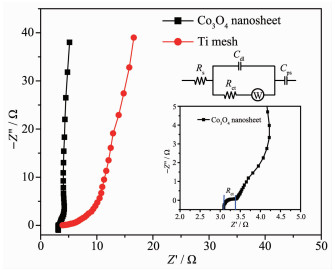
To further evaluate the electrochemical behavior of the electrode material, electrochemical impedance spectroscopy (EIS) was also collected with a frequecy ranging from 100 kHz to 0.1 Hz at open circuit potential, and the corresponding Nyquist plots are exhibited in Fig. 6. The inset in Fig. 6 was the equivalent circuit fitted by ZSimpWin. The EIS data can be fitted by internal resistance (Rs), charge transfer resistance (Rct), double layer capacitor (Cdl), Warburg impendence (Zw), and Cps for the limited pseudo-faradic reaction, as shown in the inset in Fig. 6. In the high frequency region, the spectra of layered Co3O4 electrode showed a semicircle, and the intercept of arc on the x-axis was represented the Rs with a value of 3.09 Ω, which included intrinsic resistance of ionic resistance of electrolyte, and contact resistance with current collector. The Rct related to the semicircle was estimated as 0.29 Ω, which demonstrated much lower resistance to many other Co3O4 electrode reported before (Table 1)[19, 33-40]. The high-rate capability and excellent reversibility were attributed to the following reasons[41-42]: (1) layered structures can be resisted structural collapse and spalling, which better tolerant to high rate redox reactions during the electrochemical process; (2) layered morphology provided favourable long-range, uniform, stable and smooth oxide conductivity paths; (3) proper porosity of the material is beneficial to the penetration of electrolyte, thus reducing charge transfer resistance.
 下载:
导出CSV
下载:
导出CSV
| Electrode | Electrolyte | Rct/Ω | Reference |
| Layered Co3O4 nanosheet | KOH (2 mol·L-1) | 0.29 | This work |
| Ultrathin Co3O4 nanosheets | KOH (6 mol·L-1) | ≈0.3 | [33] |
| Ultrathin Co3O4 nanomeshes | KOH (2 mol·L-1) | ≈3 | [19] |
| Co3O4/graphene | KOH/polyvinyl alcohol | 20.66 | [34] |
| Co3O4 nanosheet | KOH (2 mol·L-1) | 0.06 | [35] |
| Co3O4@carbon nanotube | KOH (0.5 mol·L-1) | ≈2.5 | [36] |
| NiO nanosheet arrays | KOH (1 mol·L-1) | 0.66 | [37] |
| ZnO/Co3O4 nanorod | KOH (1 mol·L-1) | 87.9 | [38] |
| Co3O4@MnO2 nanosheet | KOH (1 mol·L-1) | ≈50 | [39] |
| Tremella-like NiO@Co3O4@MnO2 | KOH (6 mol·L-1) | ≈ 1 | [40] |
The cycle life is another important factor for evaluating the performance of supercapacitor. The cyclic performance of layered Co3O4 sample for 1 000 cycles at current density of 100 mA·g-1 is presented in Fig. 7.
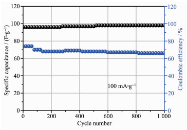
During the 1 000 charge-discharge processes, the corresponding coulombic efficiency approached 98%, which confirmed that the material possesseed good reversibility. A capacitance retention of 91.8% was observed after 1 000 charge-discharge cycles, indicating the excellent stability of the 2D porous layered nanosheets electrode.
In summary, layered Co3O4 on Ti mesh have been synthesized by a facile route as flexible supercapacitor electrode. The prepared layered Co3O4 nanosheets possessed long-range 2D conductivity paths with high surface area and porous nature, which exhibited excellent electrochemical performance towards the EIS, such as lower charge transfer resistance (Rct). This layered Co3O4 with the excellent structural and electrochemical stability with 98% coulombic effeciency may be very useful for the flexible electrode for the energy storage devices.
Guo D, Luo Y Z, Yu X Z, et al. Nano Energy, 2014, 8:174-182 doi: 10.1016/j.nanoen.2014.06.002
Nishide H, Oyaizu K. Science, 2008, 319:737-738 doi: 10.1126/science.1151831
Simon P, Gogotsi Y. Nat. Mater., 2008, 7:845-854 doi: 10.1038/nmat2297
Wang G P, Zhang L, Zhang J J. Chem. Soc. Rev., 2012, 41:797-828 doi: 10.1039/C1CS15060J
Chen L F, Huang Z H, Liang H W, et al. Adv. Funct. Mater., 2014, 24:5104-5111 doi: 10.1002/adfm.201400590
Ling M, Qian X Y, Zhu D Z, et al. Chin. Chem. Lett., 2019, https://doi.org/10.1016/j.cclet.2019.03.010.
Kumbhar V S, Kim D H. Electrochim. Acta, 2018, 271:284-296 doi: 10.1016/j.electacta.2018.03.147
Xue D F, Zhu D Z, Xiong W, et al. ACS Sustainable Chem. Eng., 2019, 7:7024-7034 doi: 10.1021/acssuschemeng.8b06774
Hu Q Q, Gu Z X, Zheng X T, et al. Chem. Eng. J., 2016, 304:223-231 doi: 10.1016/j.cej.2016.06.097
Zhang Z Y, Liu S S, Xiao F, et al. ACS Sustainable Chem. Eng., 2017, 5:529-536 doi: 10.1021/acssuschemeng.6b01879
Jiang J, Liu J P, Huang X T, et al. Cryst. Growth Des., 2010, 10:70-75 doi: 10.1021/cg9001835
Qiu K, Lu Y, Cheng J, et al. Electrochim. Acta, 2015, 157:62-68 doi: 10.1016/j.electacta.2014.12.035
Wang X H, Yao S W, Wu X X, et al. RSC Adv., 2015, 5:17938-17944 doi: 10.1039/C4RA14450C
Liu T, Zhang L Y, You W, et al. Small, 2018, 14:1702407 doi: 10.1002/smll.201702407
Li Z P, Yu X Y, Paik U. J. Power Sources, 2016, 310:41-46 doi: 10.1016/j.jpowsour.2016.01.105
Qorbani M, Naseri N, Moshfegh A Z. ACS Appl. Mater. Interfaces, 2015, 7:11172-11179 doi: 10.1021/acsami.5b00806
Meher S K, Rao G R. J. Phys. Chem. C, 2011, 115:15646-15654 doi: 10.1021/jp201200e
Xu Y Q, Wang Z L, Tan L, et al. Ind. Eng. Chem. Res., 2018, 57:5259-5267 doi: 10.1021/acs.iecr.8b00170
Wei G J, Zhou Z, Zhao X X, et al. ACS Appl. Mater. Interfaces, 2018, 10:23721-23730 doi: 10.1021/acsami.8b04026
Chen D H, Peng L L, Yuan Y F, et al. Nano Lett., 2017, 17:3907-3913 doi: 10.1021/acs.nanolett.7b01485
Sennu P, Aravindan V, Lee Y S. J. Power Sources, 2016, 306:248-257 doi: 10.1016/j.jpowsour.2015.12.029
Wang Y, Huang J, Xiao Y J, et al. Carbon, 2019, 147:146-153 doi: 10.1016/j.carbon.2019.02.082
Yu L Y, Hu L F, Anasori B, et al. ACS Energy Lett., 2018, 3:1597-1603 doi: 10.1021/acsenergylett.8b00718
Aloqaylia S, Ranaweeraa C K, Wanga Z, et al. Energy Storage Mater., 2017, 8:68-76 doi: 10.1016/j.ensm.2017.05.006
Xu R, Lin J M, Wu J H, et al. Appl. Surf. Sci., 2018, 434:861-870 doi: 10.1016/j.apsusc.2017.10.174
An K L, Zheng Y, Xu X X, et al. J. Solid State Chem., 2019, 270:539-546 doi: 10.1016/j.jssc.2018.12.021
Shakir D, Shahid M, Rana U A, et al. Electrochim. Acta, 2014, 129:28-32 doi: 10.1016/j.electacta.2014.02.082
Saray M T, Hosseini H. Electrochim. Acta, 2016, 222:505-517 doi: 10.1016/j.electacta.2016.11.003
Chen C, Zhou J J, Li Y L, et al. J. Solid State Chem., 2019, 271:239-245 doi: 10.1016/j.jssc.2018.12.060
Luo G X, Teh K S, Xia Y, et al. J. Alloys Compd., 2018, 767:1126-1132 doi: 10.1016/j.jallcom.2018.07.188
Feng C, Zhang J F, He Y, et al. ACS Nano, 2015, 9:1730-1739 doi: 10.1021/nn506548d
Pan G X, Xia X H, Cao F, et al. Electrochim. Acta, 2015, 173:385-392 doi: 10.1016/j.electacta.2015.05.078
Xiao Z Y, Fan L L, Xu B, et al. ACS Appl. Mater. Interfaces, 2017, 9:41827-41836 doi: 10.1021/acsami.7b10309
Liao Q Y, Li N, Jin S X, et al. ACS Nano, 2015, 9:5310-5317 doi: 10.1021/acsnano.5b00821
Rakhi R B, Chen W, Hedhili M N, et al. ACS Appl. Mater. Interfaces, 2014, 6:4196-4206 doi: 10.1021/am405849n
Wang X W, Li M X, Chang Z, et al. ACS Appl. Mater. Interfaces, 2015, 7:2280-2285 doi: 10.1021/am5062272
Huang M, Li F, Ji J Y, et al. CrystEngComm, 2014, 14:2878-2884 https://www.researchgate.net/publication/272263709_Facile_synthesis_of_single-crystalline_NiO_nanosheet_arrays_on_Ni_foam_for_high-performance_supercapacitors
Gao M, Wang W K, Rong Q, et al. ACS Appl. Mater. Interfaces, 2018, 10:23163-23173 doi: 10.1021/acsami.8b07082
Guo W, Hou L L, Hou B, et al. J. Alloys Compd., 2017, 708:524-530 doi: 10.1016/j.jallcom.2017.02.276
Wang H, Ren Q, Brett D J L, et al. J. Power Sources, 2017, 343:76-82 doi: 10.1016/j.jpowsour.2017.01.042
Wu X, Han Z C, Zheng X, et al. Nano Energy, 2017, 31:410-417 doi: 10.1016/j.nanoen.2016.11.035
Ouyang Y, Huang R J, Xia X F, et al. Chem. Eng. J., 2019, 355:416-427 doi: 10.1016/j.cej.2018.08.142

Figure 3 (a, b) Low and (c, d) high magnification SEM images of Co3O4 sample
Inset of (a) and (b) were the low resolution SEM images of Co3O4 and the Ti mesh substrate respectively

Figure 4 (a, b) Low-magnification TEM images of the mesoporous Co3O4 nanosheet; (c, d) HRTEM images of the edge part of the Co3O4 nanosheet

Figure 5 (a, b) Low-magnification TEM images of the mesoporous Co3O4 nanosheet; (c, d) HRTEM images of the edge part of the Co3O4 nanosheet Fig. 5 (a) CV curves of layered Co3O4 nanosheet electrode at different scan rates; (b) Cs as a function of scan rate; (c) Charge and discharge curves of samples at different current densities; (d) Cs as function of discharge current densities of layered Co3O4 electrode

Figure 7 Long cycle performance of Co3O4 nanosheet arrays measured at the current density of 100 mA·g-1
Table 1. Rct for different structured metal oxide
| Electrode | Electrolyte | Rct/Ω | Reference |
| Layered Co3O4 nanosheet | KOH (2 mol·L-1) | 0.29 | This work |
| Ultrathin Co3O4 nanosheets | KOH (6 mol·L-1) | ≈0.3 | [33] |
| Ultrathin Co3O4 nanomeshes | KOH (2 mol·L-1) | ≈3 | [19] |
| Co3O4/graphene | KOH/polyvinyl alcohol | 20.66 | [34] |
| Co3O4 nanosheet | KOH (2 mol·L-1) | 0.06 | [35] |
| Co3O4@carbon nanotube | KOH (0.5 mol·L-1) | ≈2.5 | [36] |
| NiO nanosheet arrays | KOH (1 mol·L-1) | 0.66 | [37] |
| ZnO/Co3O4 nanorod | KOH (1 mol·L-1) | 87.9 | [38] |
| Co3O4@MnO2 nanosheet | KOH (1 mol·L-1) | ≈50 | [39] |
| Tremella-like NiO@Co3O4@MnO2 | KOH (6 mol·L-1) | ≈ 1 | [40] |
 下载: 导出CSV

 扫一扫看文章

扫一扫关注我们