Citation:
HUANG Qing-Li, WANG Li-Li, LI Ting, WU Yong-Ping. Synthesis, Growth Mechanism and Application in Anticancer of CuS Hollow Spheres[J]. Chinese Journal of Inorganic Chemistry,
2019, 35(2): 314-322.
doi:
10.11862/CJIC.2019.032
Received Date:
21 June 2018 Revised Date:
20 November 2018 Available Online:
10 February 2019
Abstract:
Cage-like hollow morphologies of copper sulfide nanostructures have been selectively synthesized using cupric nitrate trihydrate (Cu(NO3)2·3H2O), oxalic acid (H2C2O4) and sodium sulphide nonahydrate (Na2S·9H2O) as starting materials in water solution by a self sacrificing templates hydrothermal method. X-ray diffraction (XRD), field scanning electron microscopy (FESEM), transmission electron microscopy (TEM) and high-resolution transmission electron microscopy (HRTEM) were used to characterize the products. The possible formation mechanism of CuS hollow spheres was proposed. The photo-thermal conversion experiments were also done. The results showed that hollow CuS exhibited high photo-thermal efficiency and high anticancer activity under NIR irradiation.
Cancer is one of the leading causes of death worldwide and the incidence rate is increasing year by year. However, current chemo-and radiation therapies have many well-known disadvantages, including systemic side effects, relatively poor specificity toward malignant tissues, drug resistance and low efficacy. Recently, near-infrared (NIR) photo-thermal therapy (PTT) has gained popularity[1-4]. Various kinds of NIR laser-induced photo-thermal agents have been widely investigated such as noble metal nanostructures[5-6], carbon-based materials[7-8], chalcogenide semiconduc-tors[9-14]. Among these photo-thermal agents, copper chalcogenide semiconductors have attracted increasing attention due to their variations in stoichio-metric composition, valence states and different unique properties[10-18]. The physical/chemical properties of nanomaterials are seriously depended on their morphology, size, composition, phase, structure and so on[18-19]. Over the past decades, considerable efforts have been focused on synthesizing various morpholo-gies of CuS nanomaterials, such as plate-like[4, 15, 20], tubular[21-22], flower-like[23], sphere-like[24-26] and dendrite-like[27] morphologies. However, cage-like hollow CuS structures were not reported.
Hollow structures of inorganic materials have received much attention because of their widespread potential applications in catalysis, drug delivery, chromatography separation, chemical reactors, contr-olled release of various substances, protection of environmentally sensitive biological molecules and cancer therapy[28-32]. Various hollow structures of inorg-anic materials have been prepared by different methods[28-32]. Nevertheless, most of the approaches for hollow structures rely on the use of either hard templates (e.g., polymer latex and mono-dispersed silica) or soft templates (e.g., ionic liquids, surfactants and micelles), which involve the adsorption of nanoparticles or polymerization on modified polymeric or inorganic template surface and subsequent removal of the templates by calcinations or dissolution with solvents. These methods often bring difficulties related to materials compatibility, high cost and complex synthetic procedures, which may prevent them from potential applications. It remains a major challenge to develop a facile, one-pot solution route for the preparation of inorganic hollow nanostructures.
Here, a simple one-pot sacrificing template synthesis of CuS hollow sphere was reported based on a mild and simple reaction between cupric nitrate trihydrate (Cu(NO3)2·3H2O), oxalic acid (H2C2O4) and sodium sulphide nonahydrate (Na2S·9H2O). A possible formation process of this novel hollow structure has been proposed on the basis of experiments. The CuS hollow sphere had the good photo-thermal conversion performance, which could be used as a photo-thermal agent for treating breast cancer and melanoma under NIR irradiation.
1.
Experimetal
1.1
Material
All the chemical reagents used in this work, including Cu((NO3)2·3H2O, H2C2O4 and Na2S·9H2O, Dulbecco′s Modified Eagles medium (DMEM) contain-ing 1%(V/V) penicillin-streptomycin, 10%(V/V) fetal calf serum (FBS), Roswell Park Memorial Institute medium (RPMI 1640) and cell counting kit-8 (CCK-8). All chemicals are analytically pure and were used as received without further purification. Deionized water was used throughout the experiment.
1.2
Methods
CuS cage-like hollow structures were prepared according to the following procedure: Firstly, 1.0 mmol of Cu((NO3)2·3H2O was dissolved in 24 mL of distilled water with magnetic stirring for 5 min and a transparent blue solution was formed. Then, 1.0 mmol H2C2O4 was added into the above solution with stirring and a blue suspension was formed. Finally, 2.0 mmol of Na2S·9H2O was added into the above suspension with magnetic stirring. The mixed solution was transferred into a Teflon-lined autoclave of 30 mL capacity, sealed and heated at 180 ℃ for 6 h, then air-cooled to room temperature. The resulting black products were collected by centrifugation, washed with distilled water and ethanol for several times, and finally dried in air at 70 ℃ for 6 h.
1.3
Characterization
The phase purity of the products was chara-cterized by X -ray diffraction (XRD, German Bruker AXSD8 ADVANCE X-ray diffractometer) using a X-ray diffractometer with Cu Kα radiation (λ=0.154 18 nm), hybrid monochromators, and X accelerator dectector. Corresponding working voltage and current, scan range (2θ) were 40 kV, 40 mA and 10°~70° respectively. Field emission scanning electron micros-copy (FE-SEM) images were taken on a HITACHI S-4800 scanning electron microscope, operating at accelerating voltage of 15 kV. Transmission electron microscopy (TEM) and high resolution transmission electron microscopy (HRTEM) images were obtained on a FEI F-30 instrument (America), using accelerating voltage of 300 kV. A 808 nm laser (2 W, LWIRL808-10W-F, Laserwave Co.) as a selected NIR light was utilized to irradiate copper sulfide aqueous dispersion (3 mL, 1 mg·mL-1) to induce photo-thermal effect. Cytotoxicity assays were conducted on amicroplate reader (Bio-rad, USA) according to a standard CCK-8 method. The relative cell viability was measured by comparing the control well containing only the cells.
1.4
Cell culture and viability assay
Cell culture: breast cancer cell MBA-MD-231 and melanoma cell B16 cells were cultured in DMEM containing 1%(V/V) penicillin-streptomycin, 10%(V/V) FBS, and incubated at 37 ℃ in an atmosphere of 5%(V/V) CO2 for 24 h. The media were changed every two days.
Cell viability assay: cytotoxicity assays were conducted according to a standard CCK-8 method. Cells were seeded in 96-well plates at a density of 1×10⁵ per well in 100 μL of DMEM containing 10%(V/V) FBS, and incubated at 37 ℃ in an atmosphere of 5%(V/V) CO2 for 24 h. Cells were then treated with the medium containing as-prepared samples. All samples were controlled equivalent, at final concentra-tions of 0, 7.8, 15.6, 31.2, 62.5, 125, 250 or 500 μg·mL-1 for 24 h. After addition of 10 μL of CCK-8 in each well, all cells were incubated for another 2 h. The absorbance of the solution at 450 nm was measured using amicroplate reader. The relative cell viability was measured by comparing the control well containing only the cells.
2.
Results and discussion
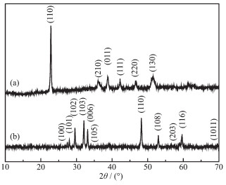
The crystalline phase and purity of the as-prepared samples were determined by XRD, and the obtained results were shown in Fig. 1. The pure monoclinic CuC2O4 (PDF No.21-0297) was prepared only using Cu((NO3)2·3H2O and H2C2O4 at the reaction temperatures of 180 ℃ for 0.1 h (Fig. 1a). Hexagonal phase CuS (PDF No.06-0464) was obtained at the reaction temperatures of 180 ℃ for 6 h by adding Na2S·9H2O (Fig. 1b). The strong and sharp XRD peaks of Fig. 1b indicate that the as-prepared CuS crystals were highly crystalline. No other diffraction peaks were found, indicating that the products were pure CuS (Fig. 1b).
Figure 1
Figure 1.
XRD patterns of (a) CuC2O4 prepared only using Cu(NO3)2·3H2O and H2C2O4 at the reaction temperatures of 180 ℃ for 0.1 h and (b) cage-like CuS hollow spheres prepared using Cu(NO3)2·3H2O, H2C2O4 and Na2S·9H2O at 180 ℃ for 6 h
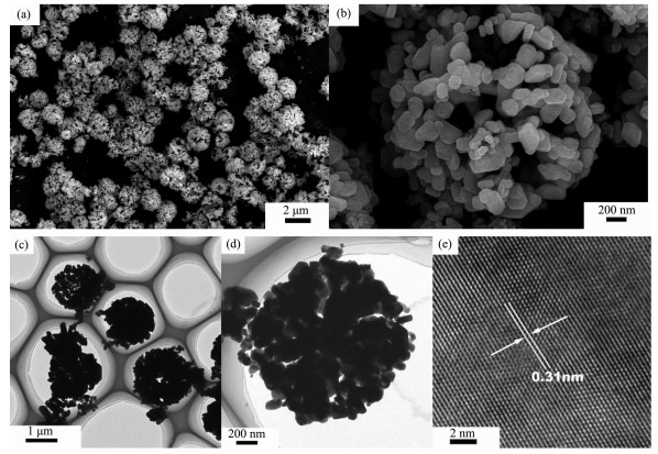
The morphologies and microstructure were studied by FESEM and TEM. Fig. 2a shows that the as-obtained samples were composed of many cage-like hollow architectures ranging from 1 to 2 μm in diameters. High magnification FESEM images revealed that these microspheres were built from small 2D nanoplates with diameter of about 200 nm (Fig. 2b). In addition, the TEM images further convinced that each sphere-like structure was made up of many small 2D nanoplates with the diameter of about 200 nm (Fig. 2(c, d)). In Fig. 2e, the HRTEM image shows sharp lattice fringes with 0.31 nm spacings, correspon-ding to the (102) planes of hexagonal phase CuS crystals. Most of the samples displayed sharp lattice fringes with no lattice defects such as stacking faults, indicating good crystallinity. This was also consistent with the result of their XRD patterns.
Figure 2
Figure 2.
(a, b) SEM, (c, d) TEM and (e) HRTEM images of CuS hollow structures prepared using Cu(NO3)2·3H2O, H2C2O4 and Na2S·9H2O at 180 ℃ for 6 h
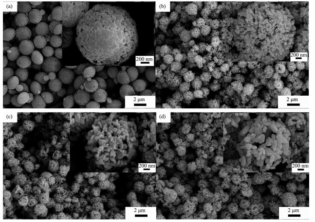
To investigate the formation mechanism of the hollow cage-like CuS sphere, their growth process was followed by examining the products collected at different aging time intervals. Fig. 3 shows the typical FESEM images of the as-prepared products at the reaction temperatures of 180 ℃ at different reaction times. Fig. 3a shows the FESEM images of the precursor (CuC2O4) obtained under hydrothermal condition for 0.1 h at 180 ℃ only using Cu((NO3)2·3H2O and H2C2O4. The resultant products consisted of many microspheres with the diameter of 1~2 μm (Fig. 3a). These spheres were constructed tightly by lots of nanoparticles (100~150 nm). By adding Na2S·9H2O and keeping 180 ℃ for 0.1 h (Fig. 3b), the size of the spheres became a bit small and these spheres were constructed loosely by lots of the smaller nanoparticles (about 50 nm). Some microspheres with hollow interior could be observed (Fig. 3b), indicating that the hollow structures began to form. When the reaction time was prolonged to 1 h, the size of these spheres was hardly changed but the size of the particles which constructed these spheres became larger (ca. 120 nm) and the shells of the spheres became thinner, as shown in Fig. 3c. After reaction for 4 h (Fig. 3d), the size of the spheres still kept unchanged and the size of the small particles which constructed these spheres further became larger (ca. 200 nm). The shells of the spheres further became thinner and all microspheres were hollow structures.
Figure 3
Figure 3.
FESEM images of (a) CuC2O4 prepared only using Cu(NO3)2·3H2O and H2C2O4 at the reaction temperatures of 180 ℃ for 0.1 h and CuS hollow spheres at different reaction times of (b) 0.1, (c) 1 and (d) 4 h
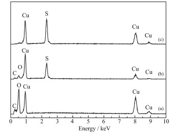
The EDS analysis of the precursor in Fig. 4a shows Cu, C and O elements in the sample, indicating the formation of pure CuC2O4 precursor. Cu, C, O and S elements were included in Fig. 4b, by adding Na2S·9H2O, coupled with a subsequent hydrothermal treatment at 180 ℃ for 0.1 h, indicating the partial transformation from CuC2O4 precursor to CuS crystal. As increasing the aging time to 6 h, only Cu and S elements were determined in Fig. 4c, indicating the complete transformation from CuC2O4 precursor to CuS hollow spheres. It is obviously that the reactions involved in the formation of CuS can be described by the following two equations:
Figure 4
Figure 4.
EDS spretra of (a) CuC2O4 prepared only using Cu(NO3)2·3H2O and H2C2O4 at the reaction temperatures of 180 ℃ for 0.1 h and CuS hollow spheres for different reaction times of (b) 0.1 and (c) 6 h
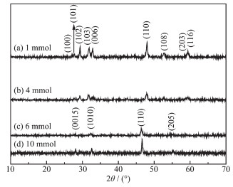
In addition, the amount of Na2S·9H2O was found to play an important role in the microstructures of the products. Fig. 5 shows the diffraction peaks of as-prepared from different amounts of Na2S·9H2O (1, 4, 6 and 10 mmol), respectively. It can be found that the as-prepared samples obtained with 1 and 4 mmol in Fig. 5a and 5b, respectively, were indexed to CuS with the hexagonal structure (PDF No.06-0464). However, with the amount of Na2S·9H2O increasing to 4 mmol, the intensity of some peaks became weak in Fig. 5b. When the addition of Na2S·9H2O reached 6 and 10 mmol, orthorhombic Cu1.8S (PDF No.23-0962) were obtained in Fig. 5c and 5d. Obviously, the phase of copper sulfides depended on the amount of Na2S·9H2O.
Figure 5
Figure 5.
XRD patterns of the samples prepared with different amounts of Na2S·9H2O at 180 ℃ for 6 h and keeping other reaction parameter constant
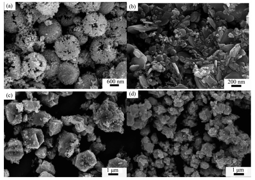
The FESEM was used further to convice the role of Na2S·9H2O. Fig. 6 shows the typical FESEM images of the products prepared with different amounts of Na2S·9H2O, keeping the amount of Cu((NO3)2·3H2O and H2C2O4 constant. When the addition of Na2S·9H2O were 1 mmol, monodispersed and homogeneous hollow spheres with diameters of about 1.5 μm could be found in Fig. 6a. With the inceasing of the addition of Na2S·9H2O to 2 mmol, cage-like hollow structures were obtained as shown in Fig. 2. These cages were built from small nanoplates with diameter of about 200 nm. When the addition of Na2S·9H2O reached 4 mmol, as illustrated in Fig. 6b, a totally different morphology of irregular plates with a diameter of about 300 nm could be observed. When the addition of Na2S·9H2O reached 6 mmol, as shown in Fig. 6c, no plates but only some polyhedrons with a diameter of about 2 μm were fabricated and well distributed in a large area. Fig. 6d indicated that the morphology were the same irregular polyhedrons but a rather smaller diameter of about 1 μm, when the addition of Na2S·9H2O reached 10 mmol. Obviously, the concentration of Na2S·9H2O was responsible for the formation of the as-prepared samples with different morphologies.
Figure 6
Figure 6.
SEM images of the CuS products prepared at 180 ℃ for 6 h with different amounts of Na2S·9H2O and keeping the amount of H2C2O4 being 1 mmol
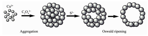
It is reasonable to presume that the formation of cage-like hollow CuS microspheres is based on Kirkendall effect and the Ostwald ripening mechanism, and the schematic illustration was shown in Schematic 1[33-35]. At the first stage, tiny CuC2O4 precursor nano-particles were quickly produced when the C2O42- was added into the solution containing Cu2+ and sponta-neously aggregated to form large spheres to minimize their surface energy. By adding Na2S·9H2O at a low S2- concentration, CuC2O4 behaved as templates in the following process of the reaction. S2- ions reacted with CuC2O4 microspheres to form a thin layer of CuS on the surfaces of the CuC2O4 microspheres. The thin layers were actually composed of many small CuS crystallites. With the aging time increasing, on one hand, the small CuS crystallites grew larger by Ostwald ripening; on the other hand, CuC2O4 gradually dissolved into Cu2+ and C2O42-, and Cu2+ diffused outward to continue the reaction with S2-. In this way, CuS with hollow structures were finally formed. However, high S2- concentration will destroy the sphere-like struc-tures of CuC2O4 and easily result in the formation of copper-rich sulfides, which should be attributed to more easily partial reduction of Cu2+ to Cu+ in the presence of S2- with the higher concentration. Hence, the concen-tration of S2- is a important factor for the preparation of hollow CuS.
Scheme 1
Scheme 1.
Schematic illustration of the growth mechanism of CuS hollow structures
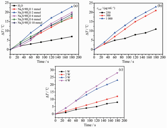
Copper sulfide has good photo-thermal conversion performance, which could be used as photo-thermal agents for treat cancer under NIR irradiation. Photo-thermal performances of copper sulfides nanostruc-tures with different morphologies and phase were investigated in their aqueous dispersion (1 mg·mL-1). Each sample was exposed to the same NIR irradiation (808 nm, continuous wave, 2 W, 180 s) and the temperature change was recorded using a temperature controller model CH702. The cage-like hollow CuS possessed the best photo-thermal efficiency in Fig. 7a (the temperature increased ~23 ℃ after NIR irradia-tion), which are consistent with early reports[36-37]. To be specific, it is noted that an amount incremental of photo-thermal conversion effect was achieved. The as-synthesized hollow CuS microspheres presented a rosy photo-thermal conversion effect due to the approach of constructing a special nanostructure with nanoparticles and cavities. Further studies showed that the photo-thermal performance also depended on the concentration of CuS aqueous suspension and laser power (Fig. 7b and 7c).
Figure 7
Figure 7.
Photo-thermal performance of samples: (a) Pure water and copper sulfides nanostructures prepared with different amount of Na2S·9H2O; (b) Different concentrations of cage-like CuS prepared with 2 mmol Na2S·9H2O upon NIR irradiation; (c) Photo-thermal performance of cage-like CuS (1 mg·mL-1) prepared with 2 mmol Na2S·9H2O with different laser power
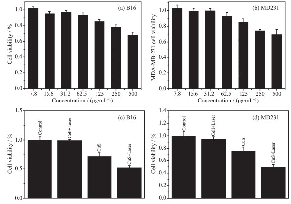
Among the wide range of nanostructures, hollow CuS nanostructures have a large specific surface area, numerous pores and good photo-thermal conversion effect[38]. These features make them have great potential in the application as both photo-thermal agents and drug-delivery carriers. Several groups have reported good anti-cancer effect of hollow CuS nanostruc-tures[38-40]. To test the cell toxicity of unique cage-like hollow CuS, the breast cancer cell MBA-MD-231 and melanoma cell B16 were incubated with a concentra-tion range of CuS prepared with 2 mmol Na2S·9H2O in Fig. 8a and 8b. It can be found that the viability of cells was higher than 70% when the concentration of cage-like CuS was increased to 500 μg·mL-1. This means that cage-like CuS were low toxic to cells. However, these cells were significantly inhibited after NIR light irradiation of low power density (600 mW·cm-2) for 3 min (Fig. 8c and 8d). In contrast, there was almost no change for the pure medium group under the same condition (Fig. 8c and 8d). This means 808 nm activated cage-like CuS, which had a lethal effect on cancer cells.
Figure 8
Figure 8.
Viabilities of (a) B16 and (b) MD231cells incubated with different dosages of cage-like hollow CuS prepared with 2 mmol Na2S·9H2O and viabilities of (c) B16 cells and (d) MD231 cell incubated with cage-like hollow CuS (500 μg·mL-1) prepared with 2 mmol Na2S·9H2O for 24 h after NIR light irradiation for 3 min
CuS as an agent for PTT, the possible mechanism was discussed. The interaction of infrared with nanomaterials, heating is the major effect[41]. It was found that elevated active oxygen species (ROS) generated with elevation of temperature to 37~50 ℃. Absorption of infrared energy stirs up the motion of charged particles and rotation of water molecules, therefore, rising the temperature. Then the formation of ROS and 8-oxoguanine were found[42]. Heat-induced ROS can damage and/or inhibit proteins in several waysone is the direct oxidation of amino acids by ROS. Here, we apply the ROS produced by CuS mediated NIR heating for cancer treatment.
3.
Conclusions
Pure hexagonal phase CuS with hollow sphere-like structures was obtained by a hydrothermal process at 180 ℃, and verified by XRD, SEM, TEM and HRTEM. The possible formation mechanism of CuS hollow spheres was discussed. the cage-like CuS exhibited excellent photo-thermal conversion performance under the irradiation of 808 nm laser, and therefore had the great potential as photo-thermal agent for anticancer. The present method is simple, reliable and can be further developed for the preparation of more metal sulfide nanostructures.
[1]
Gai S L, Yang G X, Yang P P, et al. Nano Today, 2018, 19:146-187
[2]
Shao J D, Xie H H, Wang H Y, et al. ACS Appl. Mater. Interfaces, 2018, 10:1155-1163 doi: 10.1021/acsami.7b17117
[3]
Barabadi H, Ovais M, Shinwari Z K, et al. Green Chem. Lett. Rev., 2017, 10:285-314
[4]
Feng W, Nie W, Cheng Y H, et al. Nanomed. Nanotechnol. Biol. Med., 2015, 11:901-912
[5]
Pugazhendhi A, Edison T N J, Karuppusamy I, et al. Int. J. Pharm., 2018, 539:104-111 doi: 10.1016/j.ijpharm.2018.01.034
Anderson B D, Tracy J B. Nanoscale, 2014, 6:12195-12216
[35]
Zhu H, Wang J, Wu D. Inorg. Chem., 2009, 48:7099-7104 doi: 10.1021/ic900201p
[36]
Wu D X, Duan J F, Zhang C Y, et al. J. Phys. Chem. C, 2013, 117:9121-9128
[37]
Yan C L, Tian Q W, Yang S P. RSC Adv., 2017, 7:37887-37897 doi: 10.1039/C7RA05468H
[38]
Han L, Zhang Y, Chen X W, et al. J. Mater. Chem. B, 2016, 4:105-112
[39]
Han L, Hao Y N, Wei X, et al. ACS Biomater. Sci. Eng., 2017, 12:3230-3235
[40]
Guo L R, Yan D D, Yang D F, et al. ACS Nano, 2014, 8:5670-5681
[41]
Li L H, Rashidi L H, Yao M Y, et al. Photodiagn. Photodyn. Ther., 2017, 19:5-14 doi: 10.1016/j.pdpdt.2017.04.001
[42]
Bruskov V I, Malakhova L V, Masalimov Z K, et al. Nucleic Acids Res., 2002, 30(6):1354-1363
Figure 1
XRD patterns of (a) CuC2O4 prepared only using Cu(NO3)2·3H2O and H2C2O4 at the reaction temperatures of 180 ℃ for 0.1 h and (b) cage-like CuS hollow spheres prepared using Cu(NO3)2·3H2O, H2C2O4 and Na2S·9H2O at 180 ℃ for 6 h
Figure 3
FESEM images of (a) CuC2O4 prepared only using Cu(NO3)2·3H2O and H2C2O4 at the reaction temperatures of 180 ℃ for 0.1 h and CuS hollow spheres at different reaction times of (b) 0.1, (c) 1 and (d) 4 h
Figure 4
EDS spretra of (a) CuC2O4 prepared only using Cu(NO3)2·3H2O and H2C2O4 at the reaction temperatures of 180 ℃ for 0.1 h and CuS hollow spheres for different reaction times of (b) 0.1 and (c) 6 h
Figure 7
Photo-thermal performance of samples: (a) Pure water and copper sulfides nanostructures prepared with different amount of Na2S·9H2O; (b) Different concentrations of cage-like CuS prepared with 2 mmol Na2S·9H2O upon NIR irradiation; (c) Photo-thermal performance of cage-like CuS (1 mg·mL-1) prepared with 2 mmol Na2S·9H2O with different laser power
Figure 8
Viabilities of (a) B16 and (b) MD231cells incubated with different dosages of cage-like hollow CuS prepared with 2 mmol Na2S·9H2O and viabilities of (c) B16 cells and (d) MD231 cell incubated with cage-like hollow CuS (500 μg·mL-1) prepared with 2 mmol Na2S·9H2O for 24 h after NIR light irradiation for 3 min



 下载:
下载:

 下载:
下载: