 Figure Figure1.
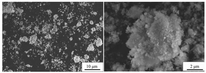
SEM image of Ni(OH)2 particles (impeller line speed 1 m·s-1)
Figure Figure1.
SEM image of Ni(OH)2 particles (impeller line speed 1 m·s-1)
Citation:
TANG Jun-Jie, LIU Yan, TIAN Lei, WANG Dong-Xing, ZHANG Ting-An. Influence of Flow Field Distribution on the Crystallization of Spherical Nickel Hydroxide in Reactor[J]. Chinese Journal of Inorganic Chemistry,
2016, 32(7): 1127-1134.
doi:
10.11862/CJIC.2016.156

反应器内流场分布对球形氢氧化镍生长结晶的影响
English
Influence of Flow Field Distribution on the Crystallization of Spherical Nickel Hydroxide in Reactor
Abstract:
The spherical nickel hydroxide was synthesized by chemical precipitation method under the conditions of the same stay time but different linear velocities of the stirring blades. Then the morphologies of the spherical Ni(OH)2 were characterized by SEM. In the same retention time and chemical condition, it was found that with increasing the linear velocity, the morphology of the spherical Ni(OH)2 changed from amorphous crystals to large near spherical particles at first, and then to regular spherical crystals finally. The flow field distribution in the reactor was simulated by PIV physical model technology. And XRD results show that in the same retention time and chemical condition, more uniform flow field distribution in the reactor and higher velocity vector can lead to more complete Ni(OH)2 crystals, higher relative crystallinity and higher degree of sphericity. Moreover, the crystallization process of spherical Ni(OH)2 was described from the flow field viewpoint.
-
Key words:
- spherical Ni(OH)2
- / flow field distribution
- / relative crystallinity
- / crystallization
-
0 Introduction
Spherical Ni(OH)2 is one of the most important battery materials which has been widely applied in communication, spaceflight, digital and so on. Some problems such as large structure differences in different batches always appear in the manufacture of spherical Ni(OH)2 products. Peng et al. studied the influence of turbine blade and propelled paddle on the crystalliza-tion of spherical Ni(OH)2, and they concluded that in the same energy consumption, the use of turbine blade can get more uniform growth product[1-3]. Shen et al. explained the growth process of spherical Ni(OH)2 crystal by a growth model[4-5]. Al-Hajry et al. studied the growth of flower-shaped Ni(OH)2 crystal, and they suggested that the flower-shaped crystal is consisted of thin nanosheets which are connected each other and they form network-like morphologies[6]. Hironori et al. studied the crystal growth of β-Ni(OH)2 in hydrothermal synthesis process, and the changes of the number and size of crystals with the hydrothermal reaction period were quantitatively analyzed by using the TEM images. Moreover, the crystallization was controlled by the size limit of the nanochannels[7].
The stirring plays a key role in the control of the crystallization process. Sancho et al. studied the characteristics of the mixing layer flow in a cylindrical reactor by PIV and PLIF technology, and they concluded that the rapid irreversible reaction particles with smaller displacement in the flow field cannot significantly increase the reaction rate, but it can improve the mixing degree of the reactants[8-13]. Fukushima et al. used the PIV and PTV technique to investigate the particle dispersion in different regions of the reactor during the mixing process, and get relevant experience for controlling the crystallization which is related to concentration[14-15].
The control of the spherical Ni(OH)2 crystallization has great relationship to the concentration of the material in the reactor and the degree of mixing. To investigate the process of the spherical Ni(OH)2 crystallization, scientists mainly take the temperature, pH value (ammonia content), reactant supersaturation, mixing intensity and paddle type and other aspects into consideration at present. However, the influence of the field distribution inside reactor on the crystal growth of spherical Ni(OH)2 was rarely studied. Therefore, in this study the spherical Ni(OH)2 was synthesized by chemical precipitation method under different linear velocities of the stirring blades. The morphologies and relative crystallinity of the spherical Ni(OH)2 were characterized by SEM and XRD. Then the flow field distribution in the reactor under different linear velocities of the stirring blades was simulated by PIV physical model technology. The relationship between flow flied distribution and Ni(OH)2 crystallization was concluded from the experimental and simulation results. This study provides a theoretical basis and experience, both for reducing the structure difference in Ni(OH)2 industrial products and the structure design of industrial reactor.
1 Experimental
1.1 Reactor design
According to the investigation on the spherical Ni(OH)2 industrial production reactor, and the under-standing of the hydrodynamic conditions such as the velocity field, concentration field, temperature field and residence time distribution in the reactor and the transfer behavior, a 200 L organic glass model reactor was designed by NL=Ns(DS / DL)X similar geometry principle (for this system the magnification factor X=1~3/4, because the industrial chemical precipitation method for the preparation of spherical Ni(OH)2 system is solid-liquid suspension system).
1.2 Preparation of spherical Ni(OH)2
According to the industrial process of spherical Ni(OH)2 preparation, the chemical precipitation method was applied to the preparation of spherical Ni(OH)2 in this experiment. The reaction temperature of the system is controlled at 50~57 ℃, and the pH value is controlled at 11~11.7. A certain concentration of nickel sulfate solution, ammonia, sodium hydroxide solution in a certain proportion was filled to the bottom of the reactor. Under the same residence time, the sample is prepared under the stirring paddle line speed of 1, 3, 5 and 7 m·s-1, and then the sample is filtered and washed to dry, waiting for measurement.
1.3 SEM experiments
When the impeller line speed is 1 m·s-1 and 3 m·s-1, the Ni(OH)2 particles are irregular shape crystals with different size, and the surface of the crystal is formed by the stacking of lamella micro-crystals with attached particles, such as Fig. 1~2. When the impeller line speed is 5 m·s-1, Ni(OH)2 particles formed many near spherical crystals, the surface of which is formed by the accumulation of many well-defined lamellar micro-crystals, such as Fig. 3. When the impeller line speed is 7 m·s-1, Nickel hydroxide particles formed spherical crystals with similar morphology and size, and the surface of these crystals is composed of the accumulation of many micro-crystals with clear stripes, such as Fig. 4.
Figure Figure1.
SEM image of Ni(OH)2 particles (impeller line speed 1 m·s-1)
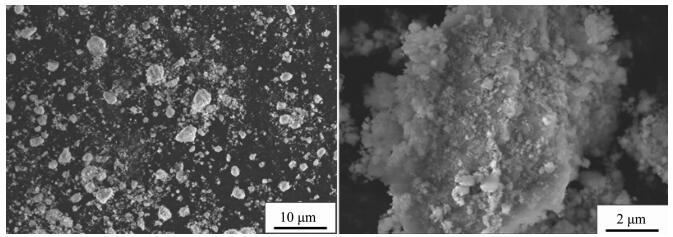 Figure Figure2.
SEM image of Ni(OH)2 particles (impeller line speed 3 m·s-1)
Figure Figure2.
SEM image of Ni(OH)2 particles (impeller line speed 3 m·s-1)
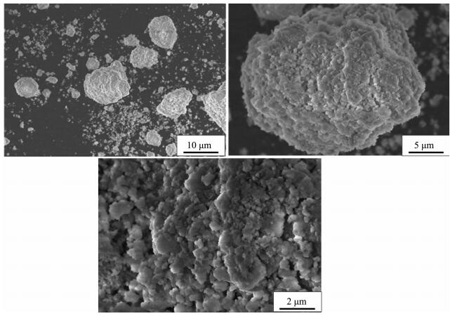 Figure Figure3.
SEM image of Ni(OH)2 particles (impeller line speed 5 m·s-1)
Figure Figure3.
SEM image of Ni(OH)2 particles (impeller line speed 5 m·s-1)
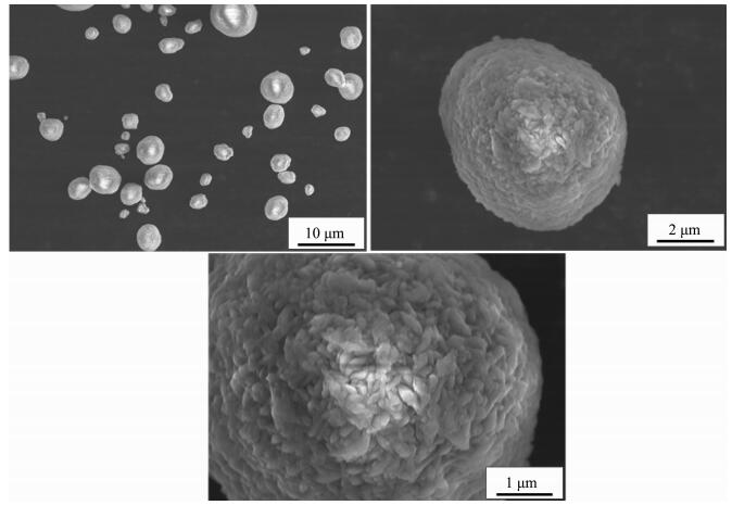 Figure Figure4.
SEM image of Ni(OH)2 particles (impeller line speed 7 m·s-1)
Figure Figure4.
SEM image of Ni(OH)2 particles (impeller line speed 7 m·s-1)
2 Results and discussion
2.1 PIV analysis
The crystallization porcess of spherical Ni(OH)2 crystal can be divided into nucleation and crystal growth. Therefore, if the nucleus formation speed is fast and the crystal growth rate is slow, the nucleus will gradually form amorphous Ni(OH)2 crystal. Ammonia is commonly used as a compounding agent which reacts with nickel ions to lower the concentration of reactants in industry, and the nucleation and growth rate of nickel hydroxide crystal can reach a reasonable reaction rates to form spherical nickel hydroxide (Equation 1). The flow velocity vector and distribution in the reactor determine the mixed uniform rate and state of reagent and ingredient, which also indirectly affects the crystallization, spheri-city, growth uniformity of spherical Ni(OH)2 and other important products indicators.
When the impeller line speed is 1 m·s-1, the cloud image of the absolute velocity vector in the reactor is shown in Fig. 5. It can be seen from the graph that in both sides and the bottom area of the mixing paddle the velocity vector distribution is larger, which is the relatively high velocity zone of the liquid flow, and the direction of the liquid flow is from the bottom to the top. Three stirring circulation appeared in the reactor A, B and C areas, and the velocity vector in A, B and C areas is lower than other areas. When the impeller line speed is 3 m·s-1, the cloud image of the absolute velocity vector in the reactor is shown in Fig. 6. It can be seen from the graph that in both sides and the bottom area of the mixing paddle the velocity vector distribution is larger than before, but in the three circulation flow areas the velocity vector distributions show no significantly change. The area such as A, Band C is named as stirring dead zone. In the above two kinds of flow field distribution, because the velocity vector distribution in the reactor is low, the range of the stirring dead zone increases, which leads to the slowly mixing rate of the reaction materials and cooperation agent ammonia, and to low mixed degree of uniformity, consequently the Ni(OH)2 crystal nucleation rate is fast but crystal growth rate is slow, forming amorphous crystalline with varying sizes (Fig. 1~2).
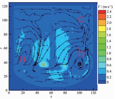 Figure Figure5.
Cloud image of the system (absolute velocity vector 1 m·s-1)
Figure Figure5.
Cloud image of the system (absolute velocity vector 1 m·s-1)
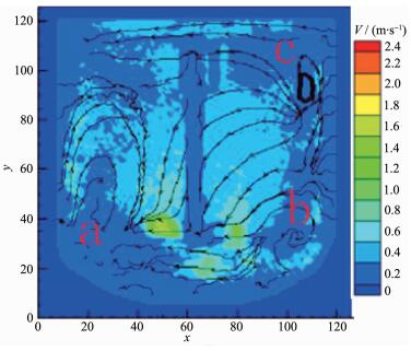 Figure Figure6.
Cloud image of the system (absolute velocity vector 3 m·s-1)
Figure Figure6.
Cloud image of the system (absolute velocity vector 3 m·s-1)
As shown in Fig. 7, when the impeller line speed increases to 5 m·s-1, the fluid flow direction is from bottom to up, which is similar to that when the impeller line speed is 1 and 3 m·s-1. The relatively high liquid flow velocity region at both sides of the shaft and the bottom of the stirring paddle expands and the velocity vector increases. At the A, B and C areas the stirring circulation velocity reactor show little variation with the increase of the stirring paddle line speed, but the mixing circulation range is reduced obviously. Due to increasing the flow velocity vector in the reactor and decreasing the stirring dead zone range, the mixed uniform extent of reactor reactant and cooperation agent raise, same to mixing rate. Ni(OH)2 particles get together and grow into many large spherical crystals (Fig. 7). Since in the reactor flow velocity vector and distribution uniform has not achieved ideal value, the aggregation growth of the spherical crystals does not aggregate, and not collide with each other and break to enter into the secondary crystallization stage, therefore does not form good sphericity of spherical nickel hydroxide crystal.
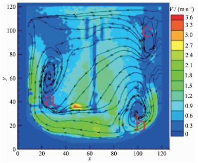 Figure Figure7.
Cloud image of the system (absolute velocity vector 5 m·s-1)
Figure Figure7.
Cloud image of the system (absolute velocity vector 5 m·s-1)
As shown in Fig. 8, when the impeller line speed increases to 7 m·s-1, the relatively high liquid flow velocity region at both sides of the shaft and the bottom of the stirring paddle expands and the velocity vector continues to increase, and at the A, B and C areas the stirring circulation velocity reactor still doesn't increase obviously, but the mixing circulation range gets smaller. Due to the change of the fluid flow distribution in the reactor, the mixed uniform extent of reactor reactant and mixing rate continue to rise. The nucleation rate and growth rate of the Ni(OH)2 crystals reached a relative equilibrium, and under high speed flow field larger crystals formed many crystalline, sphericity, homogeneous volume spherical Ni(OH)2 crystal by collision crushing secondary crystallization (Fig. 8).
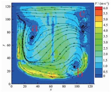 Figure Figure8.
Cloud image of the system (absolute velocity vector 7 m·s-1)
Figure Figure8.
Cloud image of the system (absolute velocity vector 7 m·s-1)
The agglomeration effect of particles plays a key role in the entire process of the crystal growth of spherical Ni(OH)2[1]. When the impeller line speed is 1 or 3 m·s-1, the flow velocity vector is low and flow field distribution is not uniform in the reactor, which leads to the results that the mixed uniformity of the reactant is low, therefore, agglomeration rate of Ni(OH)2 particles is low. So most of the nickel ion and ammonia ions does not occur the complexation reaction, but formed the nickel hydroxide precipitation. When the stirring paddle line speed increases to 5 m·s-1, the flow velocity vector becomes larger in the reactor, and the stirring circulation dead range is narrow, the flow field distribution is more uniform, so the mixed uniformity of the complexing agent and reactant improved, and more nickel ions complexation reacts with ammonia ions, which lead to slow rate of crystal nucleation, and to increasing crystal aggregation rate at the same time, particles agglomerate into many complete crystallization of large crystals with the same residence time. It can be concluded that as increasing flow velocity vector and uniform distribution in the reactor, the nickel hydroxide particles aggregation rate and sphericity also increases. When the stirring paddle line speed is 7 m·s-1, the distribution of flow field in the reactor and uniformity of velocity vector reach an ideal value, and the mixing of the complexing agent and the reactant reach an ideal state, and appropriate complexing reaction balance the crystal nucleation and crystal growth rate. At high speed flow field some large crystal aggregates collide and break to occur the secondary crystallization, and spherical nickel hydroxide crystals with uniform size and high degree form. It is shown that in the reactor only flow velocity vector reach a fixed value, large particles of Ni(OH)2 crystal can lead to aggregation burst into the secondary crystallization, therefore, the crystal growth of uniformity is improved.
2.2 XRD analysis
The XRD instrument used in this experiment is D8 Advance X XBruker ray analyzer produced by German Bruker company. Light tube type is Cu target, ceramic X light tube. λ=0.154 06 nm, scan range is 10°~90°, the scanning speed is 2°·min-1. XRD patterns of the samples which were prepared at different mixing speed is shown in Fig. 9.
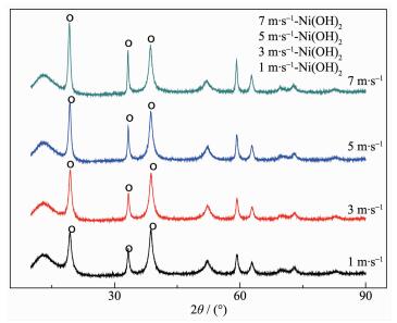 Figure Figure9.
XRD patterns of the samples at different mixing speed
Figure Figure9.
XRD patterns of the samples at different mixing speed
From Fig. 9 it can be found that the main peak is nickel hydroxide, and other crystal items were not observed. When the line speed is 7 m·s-1, the diffrac-tion peak in the XRD spectrum is highest, the half width of the peak is minimum, and the relative crystallinity of the best. If the best relative degree of crystallinity samples prepared at 7 m·s-1 is treated as relative crystallinity of 100%, according to amorphiza-tion formula A=(1-U0Ix / UxI0)×100%, the calculation of amorphous salinity of each sample is plotted in a linear graph, as shown in Fig. 10. Moreover, the rela-tionship between line speed V (m·s-1) and amorphiza-tion: A=1-0.479 4e0.104 1V can be obtained according to Fig. 10.
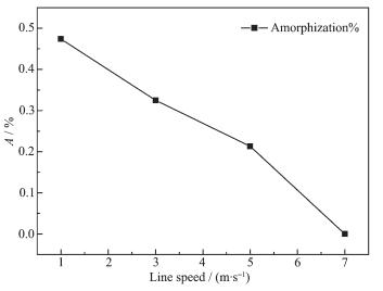 Figure Figure10.
Relationship between line speed and amorphization
Figure Figure10.
Relationship between line speed and amorphization
2.3 Relative particle size difference analysis
The particle size distribution instrument used in this experiment is MASTERSIZER 2000 produced by Malvern Instruments Ltd. The particle size distribution of the sample at different mixing speed is given in Table 1. From Table 1 it can be found that when the line speed is 7 m·s-1, the relative particle size difference F=d0.9-d0.5 is minimum. Moreover, according Table 1 can be obtained Fig. 11. From Fig. 11 can lead to the relationship between relative particle size difference and line speed: F(0.5~0.9)=-15.59lnV+41.172.
 Table 1.
Particle size distribution and size difference
Table 1.
Particle size distribution and size difference
Line speed/(m·s-1) 1 3 5 7 d0.5/μm 8.406 4.505 4.777 11.214 d0.9/μm 50.076 26.781 22.425 21.747 (d0.9-d0.5)/μm 41.670 22.276 17.648 10.533 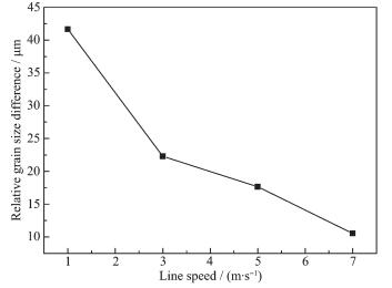 Figure Figure11.
Relative particle size difference at different mixing speed
Figure Figure11.
Relative particle size difference at different mixing speed
2.4 CV analysis
The electrochemical activity is the basic indicator of Ni(OH)2. The Ni(OH)2 samples prepared of different stirring line speeds are compressed with carbon black and adhesive in proportion as 7:2:1 into sheets electrode. CV Scan is tested at the speed of 10 mA·s-1 in the range of 0~0.6 V, while the Hg/HgO is selected as the contrast electrode. The cycle voltammogram is shown in Fig. 12. When the line speed is 7 m·s-1, the area of electrochemical activity and peak current reach the maximum, which show the best electrochemical performance.
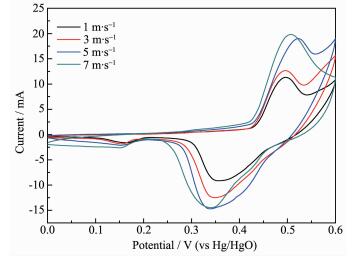 Figure Figure12.
CV curves of Ni(OH)2 samples at different mixing speed
Figure Figure12.
CV curves of Ni(OH)2 samples at different mixing speed
3 Conclusions
(1) In the same retention time and chemical condition, the growth integrity, uniform, crystallization, sphericity and the particles aggregation rate of spher-ical Ni(OH)2 crystals is proportional to the distribution range of the flow velocity vector and uniformity in the reactor.
(2) In the same retention time and chemical condition, large particles of Ni(OH)2 crystals can lead to aggregation burst and the secondary crystallization to form Ni(OH)2 crystals with uniform size when flow velocity vector in the reactor reaches a fixed value. Moreover, from the particle size distribution at different line speed the relationship between relative particle size difference F (μm) and line speed V (m·s-1); F(0.5~0.9)=-15.59lnV+41.172 can be obtained.
(3) In the same retention time and chemical condition, from the XRD characterization it can be obtained that the relative crystallinity of Ni(OH)2 crystals is proportional to the velocity distribution of the flow field size and uniformity in the reactor, and nickel hydroxide is proportional to the distribution range of the flow velocity vector and uniformity in the reactor. But the velocity distribution of the flow field size and uniformity in the reactor does not affect the crystalliz-ation of other crystal items. Moreover, the relationship between line speed V (m·s-1) and amorphization: A=1-0.479 4e0.104 1V can be obtained according XRD.
(4) The electrochemical activity of Ni(OH)2 is proportional to the uniformity of flow distribution and velocity vector in the container when the residence time has no change. Moreover, it is confirmed that the electrochemical activity is proportional to the relative crystallinity and growth integrality of the spherical Ni(OH)2.
-
-
[1]
彭美勋, 沈湘黔, 王零森, 等.中南大学学报, 2005, 12(1):5-8 http://kns.cnki.net/KCMS/detail/detail.aspx?filename=zngy200501001&dbname=CJFD&dbcode=CJFQPENG Mei-Xun, SHEN Xiang-Qian, WANG Ling-Seng, et al. J. Cent. South Univ. Technol., 2005, 12(1):5-8 http://kns.cnki.net/KCMS/detail/detail.aspx?filename=zngy200501001&dbname=CJFD&dbcode=CJFQ
-
[2]
Jiang L B, Zuo S B, Wang W J, et al. J. Cryst. Growth, 2011, 318(1):1089-1094 doi: 10.1016/j.jcrysgro.2010.10.092
-
[3]
Jaewon C, Seo S K, Cho G M, et al. J. Mater. Res., 2012, 27 (14):1-10
-
[4]
Kile D E, Eberl D D, Hoch A R, et al. Geochim. Cosmochim. Acta, 2000, 64(17):2937-2950 doi: 10.1016/S0016-7037(00)00394-X
-
[5]
彭美勋, 沈湘黔.中南大学学报, 2007, 14(3):310-314 http://kns.cnki.net/KCMS/detail/detail.aspx?filename=zngy200703006&dbname=CJFD&dbcode=CJFQPENG Mei-Xun, SHEN Xiang-Qian. J. Cent. South Univ. Technol., 2007, 14(3):310-314 http://kns.cnki.net/KCMS/detail/detail.aspx?filename=zngy200703006&dbname=CJFD&dbcode=CJFQ
-
[6]
Al-Hajry A, Umar A, Vaseem M, et al. Superlattices Micro-struct., 2008, 44(2):216-222 doi: 10.1016/j.spmi.2008.04.008
-
[7]
Orikasa H, Karoji J, Matsui K, et al. Dalton Trans., 2007, 34: 3757-3762 http://europepmc.org/abstract/med/17712441
-
[8]
Kühn M, Ehrenfried K, Bosbach J, et al. Exp. Fluids, 2012, 53(1):91-103 doi: 10.1007/s00348-012-1301-9
-
[9]
Xia Q F, Zhong S. Int. J. Heat Fluid Flow, 2012, 37:64-73 doi: 10.1016/j.ijheatfluidflow.2012.04.010
-
[10]
Zamankhan P. Commun. Nonlinear Sci. Numer. Simul., 2010, 15(6):1511-1525 doi: 10.1016/j.cnsns.2009.06.021
-
[11]
Kosiwczuk W, Cessou A, Trinité M, Lecordier B. Exp. Fluids, 2005, 39:895-908 doi: 10.1007/s00348-005-0027-3
-
[12]
Sancho I, Varela S, Vernet A, et al. Int. J. Heat Mass Transfer, 2016, 93:155-166 doi: 10.1016/j.ijheatmasstransfer.2015.10.011
-
[13]
Fukushima C, Aanen L, Westerweel J. Laser Techniques for Fluid Mechanics. Berlin Heidelberg: Springer, 2002:339-356
-
[14]
Gandhi M S, Sathe M J, Joshi J B, et al. Chem. Eng. Sci., 2011, 66(14):3152-3171 doi: 10.1016/j.ces.2011.02.060
-
[15]
Hua F, Olsen M J, Hill J C, et al. Chem. Eng. Sci., 2010, 65 (11):3372-3383 doi: 10.1016/j.ces.2010.02.038
-
[1]
-
Table 1. Particle size distribution and size difference
Line speed/(m·s-1) 1 3 5 7 d0.5/μm 8.406 4.505 4.777 11.214 d0.9/μm 50.076 26.781 22.425 21.747 (d0.9-d0.5)/μm 41.670 22.276 17.648 10.533  下载: 导出CSV
-


 扫一扫看文章
计量
- PDF下载量: 2
- 文章访问数: 580
- HTML全文浏览量: 116
 下载:
下载:
