Citation:
Hong-ting Pu, Jun-feng Cheng. Orientation of LDPE Crystals from Microscale to Nanoscale via Microlayer or Nanolayer Coextrusion[J]. Chinese Journal of Polymer Science,
2016, 34(12): 1411-1422.
doi:
10.1007/s10118-016-1850-0

Orientation of LDPE Crystals from Microscale to Nanoscale via Microlayer or Nanolayer Coextrusion
English
Orientation of LDPE Crystals from Microscale to Nanoscale via Microlayer or Nanolayer Coextrusion
Abstract:
The microlayer or nanolayer coextrusion of hundreds or thousands of alternating low density polyethylene (LDPE)/polystyrene (PS) microlayers or nanolayers were used to study the orientation of LDPE crystals in the confined quasi-two-dimensional or two-dimensional space. The clear and continuous layer structures from microscale to nanoscale can be found in SEM images. The morphology evolution of LDPE crystals in the confined microlayer or nanolayer can be varied from 3D spherulites, 2D spherulites, stacked edge-on lamellar, to single edge-on lamellar. Due to the orientation of the LDPE crystals, the tensile strength of the films increases obviously when the layer thickness reduces to nanoscale. The 2D small angle X-ray scattering (SAXS) patterns can reflect the average degree of orientation of LDPE in the confined layers. The stacking of LDPE lamellae is suppressed in interlamination and oppositely in parallel to the extrusion direction. The specific orientation function f can be calculated from the patterns. The infrared dichroism further confirms the mutation of the orientation of LDPE crystals from microscale to nanoscale in the confined space.
-
Introduction
Under a certain effect, the constitutional units of a polymer can be orderly oriented in a reference direction. These constitutional units include molecular chains, chain segments, crystalline grains, crystal planes or spherocrystals[1-3]. When a linear poly{Wang, 2009 #1}mer fully extends, its length is hundreds, thousands or millions times to its width. Due to this special geometric asymmetry, it is easy to form preferential arrangement under the action of the external force, and this is the orientation of the polymer[4-6]. For the non-oriented polymeric materials, their chains are randomly entangled. Accordingly, they are isotropic. For the oriented polymeric materials, the chains are aligned and exhibit anisotropy[7]. The covalent bonds act on the direction of molecular chain, whereas the van der Waals force acts on the vertical direction. Consequently, there are prominent changes in mechanical, optical, conductive, and some other properties[8]. For example, the tensile and fatigue strength increase obviously in the direction of the orientation whereas on the contrary, they decrease markedly in the vertical orthogonal[9]. In addition, in optical properties, the birefringence phenomenon can be observed[10, 11].
The characteristic crystalline and orientation morphologies can be observed when the constitutional unit is confined in a nanoscale space, such as the ultrathin films[12]. When a crystallographic polymer is confined in nanoscale, such as the ultrathin layer, the characteristic of isotropic spherulites is prevented and instead, the confined crystallization can produce the unique lamellar crystal orientation[13]. In some cases, the polymer chains are aligned parallel to the layer plane and this style of crystals is defined as edge-on lamellae. Some examples of edge-on lamellae orientation reported in the literature include high density polyethylene (HDPE)[14-16], polypropylene (iPP)[17], poly (ethylene naphthalate) (PEN)[18], poly (ethylene terephthalate) (PET)[19], and polyamide-6 (PA6)[20]. In addition, when the polymer chains are aligned perpendicular to the layer plane, it is known as flat-on lamellae. Some examples of this type include isotactic polystyrene (iPS)[21], syndiotactic polypropylene (sPP)[22], poly (ethylene oxide) (PEO)[13, 23], poly (L-lactide) (PLA)[24], poly (ε-caprolactone) (PCL)[25] and poly (3-hydroxybutyric acid)[26].
Some factors, such as the degree of crystallization, the temperature of crystallizing, the chain flexibility, the substrate-polymer interactions[27-30], and the layer thickness, can impact the lamellae orientation in the confined space[10]. In order to study the polymer crystallization and the orientation in the confined space, some conventional processes are used to create one-dimensional (1D) or two-dimensional (2D) confinement, for examples, the spin-coating[31], the substrate patterning[32], the block copolymerization[33], the blending[34], and the microlayer coextrusion[35]. Due to some unavoidable limitations of other conventional methods, the microlayer coextrusion has its unique advantages. The limitation of the solvents has narrowed down the choice of polymer on spin-coating and substrate patterning; on the other hand, the free surface may affect the properties of a spin-coated thin layer[36].Due to the difficulties of synthesis, the polymers are limited for the methods of the block copolymerization. Moreover, the final products of the block copolymers may not have long-range order and require extra shear alignment to form consistent oriented structure[37]. The miscibility of blended components limits the feasibility of blending. However, the microlayer coextrusion offers a more convenient approach to study the polymer crystallization and orientation in the confined space[38]. Two or three polymers can be combined into a continuous alternating layered structure by the microlayer or nanolayer coextrusion. Due to hundreds or thousands of layers in a film, the range of the individual layer thicknesses can be adjusted from microscale to nanoscale without changing the molecular weight of the components compared with the block copolymers. Compared to other processes, the long-range and almost defect-free confinement structure is offered via this multilayered film to study the confined polymer crystallization and orientation[39]. The overall performance of the multilayered film is multiplied many-fold by the number of independent layers in the film, although the properties of the single layer are inappreciable. This enables the use of microlayer coextrusion to probe the size dependent properties. As an example, in the present study, the orientation of edge-on LDPE lamellae unexpectedly improves the tensile strength of LDPE nanolayers by almost 50%.
Previous workers were focused on crystallization kinetics, crystal structure, and specific crystallographic planes of HDPE in HDPE/PS multilayered film[1, 40, 41]. In the present study, we focus on the crystal orientation of low density polyethylene (LDPE), which is highly branched and different from linear HDPE. The overall crystal orientation function f can be calculated by different methods. The abrupt transition of the orientation of LDPE crystals from microscale to nanoscale will be studied. Normally, the tensile strength of LDPE is relatively lower, and the improvement of the tensile strength is more obvious after the orientation of HDPE crystals. In addition, the orientation of LDPE in the confined space is more obvious due to its better chain flexibility, which can probe the orientation of the LDPE crystals from microscale to nanoscale much more conveniently.
EXPERIMENTAL
Characterization
The morphology of the cross-sections of the layered films, which were fractured in liquid nitrogen, can be observed on scanning electron microscope (SEM) (QUANTA 250FEG, FEI Co.). The actual layer thickness can also be measured by SEM. The spherulites and the lamellae were inspected by polarized optical microscopy (POM), which was performed on an Olympus BH-2 (Lake Success, NY) microscope in the transmission mode.
The tensile strength of the films was measured on WDT30 Universal Material Testing Machine (Kailiqiang Machinery Co.) according to ASTM D882-09, where the stretching rate was 50 mm/min. All the samples were tested five times, and the final results were average values.
The 2D small-angle X-ray scattering (2D SAXS) patterns were recorded on a rotating anode X-ray generator (Nanostar, 30 kW, Bruker Co.) with a highly focused parallel beam monochromatic Cu Kα radiation source (λ=0.154 nm). The entire system was operated in the vacuum environment and the range of 2θ was from 0.2° to 2.8°. The reference direction was chosen to be the extrusion direction (ED) and the normal direction (ND). The scattering profiles, which were extracted from 2D patterns, can be used to calculate Herman's orientation function f.
Fourier transform infrared (FTIR) spectroscopy (EQUINOX 55, Bruker Co.) was used to measure the infrared dichroism of LDPE/PS films. A polarizing disc was put in the light path system to create polarized infrared light. The spectrum was typically the results of 64 scans at 2 cm-1 spectral resolution, and the wavenumbers were from 400 cm-1 to 4000 cm-1.
Sample Preparation
Multilayered LDPE/PS films with PS outer layers were prepared using the microlayered coextrusion process. In order to maintain the steady melt viscosity of the two polymers, the temperature of the extruders, multiplier elements, and the die was set at 210 ℃. Then, LDPE/PS films with 4, 16, 64, 256, 512, 1024, and 2048 alternating LDPE and PS layers were coextruded. The composition ratio of LDPE/PS was set to 50/50 (V/V) to ensure the same layer thickness of LDPE and PS. The thickness of 4-layered film was 300 μm and that of the other films was about 200 μm. The nominal LDPE layer thickness can be calculated from the layer numbers and the film thickness (Table 1). The normal isotropic LDPE (Non-layered) film was prepared via solution casting from hot toluene solution (70 ℃) of LDPE.
 Table 1.
Film composition, number of layers, and calculated film thickness of LDPE/PS films
Table 1.
Film composition, number of layers, and calculated film thickness of LDPE/PS films
Sample (LDPE/PS) Film thickness (μm) Calculated layer thickness (μm) Real layer thickness (μm) LDPE PS LDPE PS 4-Layer 300 75.00 75.00 74.00 74.00 16-Layer 200 12.50 12.50 10.00 10.00 64-Layer 200 3.00 3.00 3.00 3.00 256-Layer 200 0.78 0.78 1.00 1.00 512-Layer 200 0.39 0.39 0.40 0.40 1024-Layer 200 0.20 0.20 0.26 0.26 2048-Layer 200 0.10 0.10 0.12 0.12 Table 1. Film composition, number of layers, and calculated film thickness of LDPE/PS filmsMaterials
LDPE (Q210, MFI=19.0, 190 ℃/5kg, refractive index=1.51) was obtained from Sinopec Shanghai Petrochemical Company. Polystyrene (PS) (GPPS-116, MFI=19.0, 200 ℃/5kg, refractive index=1.59) was obtained from Shanghai SECCO Petrochemical Company. LDPE and PS were individually dried at 70 ℃ in vacuum for 5 h before processing.
RESULTS AND DISCUSSION
Infrared Dichroism of PE Layers by FTIR
In general, the absorbance intensity of infrared absorption spectrum is related to the intensity and the direction of the group transition moment. If polarized infrared radiation is passed through a sample, the absorbance intensity can be the highest when the polarized light vector direction is parallel to the group transition moment direction. On the contrary, it can be zero when it is vertical. For the crystalline and the oriented polymers, some groups of the molecular chain have directivity. As a result, the change of the incident light direction will lead to the difference of the absorbance intensity. The dichroic ratio (R) is defined as the ratio of the intensity between the parallel and the perpendicular polarized light,
where
${A_{//}}$ is the absorbance in the parallel direction of the polarized infrared light;${A_ \bot }$ is the absorbance in the vertical direction.The orientation function fin terms of R can be defined as,
For a certain band, the value of R0 is constant. Therefore, f=(R-1)/(R+ 2) can be applied to characterize the degree of the polymer orientation. All the data are shown in Fig. 10 and Table 2. In Fig. 10, the imaginary line represents the infrared absorption spectrum in the extrusion direction, and the solid line represents the normal direction. The π-band at 720 cm-1 involves the rocking vibration in the plane of -(CH2)n-, 1465 cm-1 belongs to the symmetric bending vibration of -CH2-. The peak at 2853 cm-1 is the symmetrical stretching vibration of -CH2-, and 2926 cm-1 is the antisymmetric stretching vibration of -CH2-. In this work, the orientation function in the crystalline phases is calculated from the peaks at 720 and 1465 cm-1. In Fig. 10(a), the spectra of two directions of the polarized infrared light are coincident perfectly. It proves the random orientation of isotropic LDPE, and f=0. With the decrease of LDPE layer thickness, the value of R increases obviously from 1.03 to 3.35 (720 cm-1) and 1.00 to 7.60 (1465 cm-1) respectively. As a result, the orientation function f (720 cm-1) and f (1465 cm-1) increase relevantly, as shown in Fig. 11. The average orientation function f is calculated, as shown in Fig. 12. Furthermore, this variation is not obvious between 75 and 3 μm. The R value increases slightly from 1.03 to 1.09 and 1.00 to 1.04 respectively. The value of f only increases by 0.01. Compared with the final value f=0.56, the variation is insignificant. Nevertheless, R and f values get sudden raise when LDPE layer thickness decreases to 780 nm, then, f attains 0.56 when the thickness is 100 nm. This tendency of change is almost the same as the previous analysis. It reveals that the crystalline region of LDPE is oriented gradually with decreasing layer thickness.
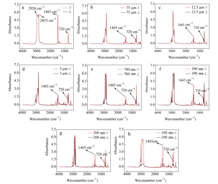 Figure 10.
Infrared dichroism profiles of PE/PS layered films with different layer thickness of LDPE, (a) isotropic PE, (b) 75 μm, (c) 12.5 μm, (d) 3 μm, (e) 780 nm, (f) 390 nm, (g) 200 nm and (h) 100 nm
Figure 10.
Infrared dichroism profiles of PE/PS layered films with different layer thickness of LDPE, (a) isotropic PE, (b) 75 μm, (c) 12.5 μm, (d) 3 μm, (e) 780 nm, (f) 390 nm, (g) 200 nm and (h) 100 nm
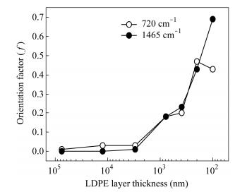 Figure 11.
Effects of LDPE layer thickness on the orientation function f (720 cm-1) and f (1465 cm-1) of LDPE lamellae by Infrared dichroism
Figure 11.
Effects of LDPE layer thickness on the orientation function f (720 cm-1) and f (1465 cm-1) of LDPE lamellae by Infrared dichroism
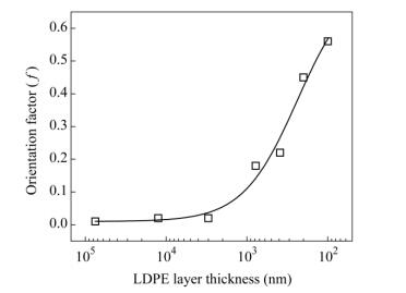 Figure 12.
Effects of LDPE layer thickness on the average orientation function (f) of LDPE lamellae by Infrared dichroism
Table 2.
Infrared dichroism data of LDPE/PS films
Figure 12.
Effects of LDPE layer thickness on the average orientation function (f) of LDPE lamellae by Infrared dichroism
Table 2.
Infrared dichroism data of LDPE/PS films
LDPE layer thickness R (720 cm-1) R (1465 cm-1) f(720 cm-1) f(1465 cm-1) f Isotropic PE 1 1 0 0 0 75 μm 1.03 1.00 0.01 0.00 0.01 12.5 μm 1.06 1.01 0.03 0.00 0.02 3 μm 1.09 1.04 0.03 0.01 0.02 780 nm 1.68 1.67 0.18 0.18 0.18 390 nm 1.76 1.89 0.20 0.23 0.22 200 nm 3.68 3.32 0.47 0.43 0.45 100 nm 3.35 7.60 0.43 0.69 0.56 Table 2. Infrared dichroism data of LDPE/PS filmsMechanical Properties of LDPE Layers
It is generally known that the polymer orientation will lead to an increase in the tensile strength of the polymer films in the direction of the orientation. In the process of the microlayer coextrusion, the molecular chains of LDPE and PS were oriented in a certain direction which can produce anisotropy of the mechanical properties. The tensile strength was tested in extrusion direction. The tensile strength of original LDPE and PS are 12 and 30 MPa respectively. When the layer thickness decreases to 780 nm, the tensile strength of the film is higher than that of original PS. With the decrease of LDPE layers from 75 μm to 3 μm, the tensile strength of the films increases slightly, and then exhibits a sharp rise between 3 μm and 780 nm, as shown in Fig. 4. These results correspond to the transformation of the LDPE spherulites. The spherulites can be compressed into the oriented lamellar when the LDPE layer thickness is less than their diameters. The orientation effects can be observed in the sudden change of the tensile strength. After this, the tensile strength increases steadily when the layer thickness decreases in the nanoscale range. The reason is that the LDPE crystals are kept in lamellar and oriented more orderly in the extrusion direction.
 Figure 4.
Effects of LDPE layer thickness on the tensile strength of HDPE layer (extrusion direction)
Figure 4.
Effects of LDPE layer thickness on the tensile strength of HDPE layer (extrusion direction)
Structure and Morphology of LDPE Layers
Due to the excellent transparency and inelasticity, the PS layer was used to confine the crystallizable LDPE layers in multilayered LDPE/PS films, which allows the spherulitic structure of the LDPE layers to be observed through the polarized optical microscope, as shown in Fig. 2. With the decrease of the layer thickness from microscale to nanoscale, the morphology of LDPE crystals are evolved according to 3D spherulites, 2D spherulites, stacked edge-on lamellar, and single edge-on lamellar, as shown in Fig. 3.
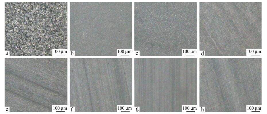 Figure 2.
Polarized optical micrographs of LDPE/PS layered films with the layer thickness of LDPE: (a) isotropic LDPE, (b) 75 μm, (c) 12.5 μm, (d) 3 μm, (e) 780 nm, (f) 390 nm, (g) 200 nm and (h) 100 nm
Figure 2.
Polarized optical micrographs of LDPE/PS layered films with the layer thickness of LDPE: (a) isotropic LDPE, (b) 75 μm, (c) 12.5 μm, (d) 3 μm, (e) 780 nm, (f) 390 nm, (g) 200 nm and (h) 100 nm
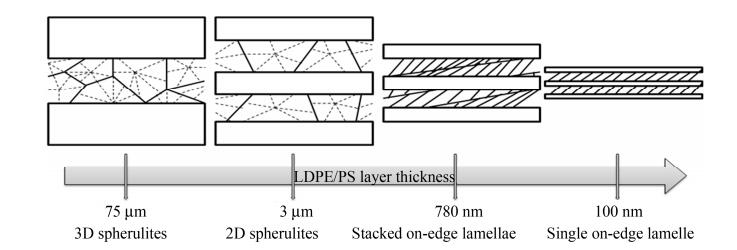 Figure 3.
Structure/morphology evolution schematic diagram of LDPE crystals in the confined space as the layer thickness is reduced from microscale (75 μm) to nanoscale (100 nm)
Figure 3.
Structure/morphology evolution schematic diagram of LDPE crystals in the confined space as the layer thickness is reduced from microscale (75 μm) to nanoscale (100 nm)
The obvious Maltese cross pattern of spherulite-like structures in LDPE layers was observed from 75 μm to 3 μm (3D spherulites to 2D spherulites). This phenomenon reveals that LDPE crystals are oriented inconspicuously. The birefringence pattern indicates that the LDPE lamellae are oriented radially with the layer thickness from 780 nm to 100 nm (stacked edge-on lamellar to single edge-on lamellar). The above phenomena agree well with other analysis results in following discussion. Generally, the lateral (edge-on) diameter of the LDPE spherulites is about 100 μm, which is larger than the thickness of LDPE layer. Therefore, the spherulites in the 75 μm LDPE layers are somewhat compressed, rather than isotropic LDPE (Fig. 2a). In 12.5 and 3 μm LDPE layers, the layer thickness is significantly less than the average flat-on dimension of the spherulite-like structures (100 μm). These spherulites are compressed as discoids. The Maltese cross pattern in multilayer films between 780 and 100 nm LDPE layers disappears gradually. Instead, little different crystal habit in LDPE nanolayers can be observed through the birefringence pattern.
Characterization on LDPE/PS Layer Structure
The SEM images of the fractured cross-sections of LDPE/PS films indicate that all the layers are clear and continuous, as shown in Fig. 1. Due to the same ratio of LDPE and PS in the multilayered films, the nominal layer thickness of each layer is roughly equal. The actual layer thickness which was marked in SEM images corresponds closely to the nominal layer thickness, as shown in Table 1. The total film thickness is 300 μm for the 4-layer films and 200 μm for the rest of the films. The relative layer numbers were varied to produce LDPE microlayers and nanolayers with different thickness of the individual layer from 75 μm to 100 nm. The actual layer thickness approximately equals to the nominal layer thickness with an error of±20%.
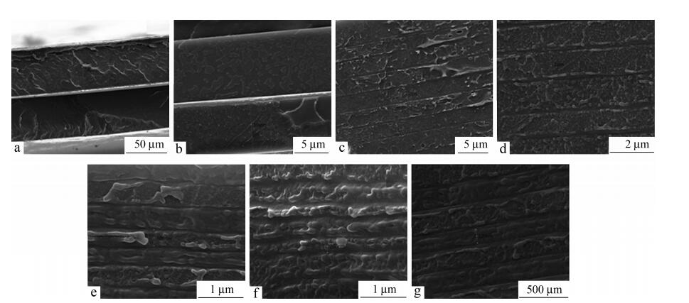 Figure 1.
SEM images of the cross-sections of LDPE/PS multilayered films with the layer thickness of LDPE, (a) 75 μm, (b) 12.5 μm, (c) 3 μm, (d) 780 nm, (e) 390 nm, (f) 200 nm and (e) 100 nm
Figure 1.
SEM images of the cross-sections of LDPE/PS multilayered films with the layer thickness of LDPE, (a) 75 μm, (b) 12.5 μm, (c) 3 μm, (d) 780 nm, (e) 390 nm, (f) 200 nm and (e) 100 nm
The light penetrating the polymeric medium is the phenomenon related to the light scattering in polymeric medium. For a film, this process includes the molecular absorbance of the medium, the internal scattering of the materials and the reflection near the interface. Effects of LDPE layer thickness on the transmissivity of the films are shown in Fig. S1 in supporting information. The transmissivity of the films decreases obviously with decreasing layer thickness. In addition, considering the effects of the wavelength on the transmissivity, it is shown in Fig. S1 that longer the wavelength, higher is the transmissivity. When the wavelength range is from 400 nm to 700 nm, any molecular absorbance of most polymeric materials can be ignored. The reflection near the interface can be defined as,
In this formula, n is the refractive index of the materials. For LDPE, n=1.51, and for PS n=1.59, thus RLDPE=4.13% and RPS=5.19%. It can be concluded that the loss of the transmissivity induced by the reflection in the LDPE/PS film can be negligible when the layer number is smaller. Thus thinner is the layer, higher is the loss of the transmissivity.
Another factor is the internal scattering of the materials. Such kind of scattering can be defined as absorbance coefficient α,
In this formula, n1 is the refractive index of the medium, n2 is the refractive index of the scattering object, Δn=n1 -n2, λ is the wavelength of the light source, vsis the volume ratio of the scattering object and medium, and V is the volume of the scattering object. From this formula, it can be deduced that the longer the wavelength is, the lower αis. As a result, the transmissivity is higher which is shown in Fig. S1. For LDPE/PS film, V2vs is a certain value, Δn=0.08, so α can be very low. Therefore, LDPE/PS film can be transparent when the layer number is small.
Lamellae Orientation in LDPE Layer by 2D Small Angle X-ray Scattering
The crystallized isotropic polymers typically show strong diffraction rings in their 2D SAXS patterns. Oppositely, the oriented polymers typically show strong two-point patterns with a maximum intensity at a certain angle to the reference direction. In Fig. 5, almost all the films show intense meridional patterns in the ED patterns; however, quite marked difference is displayed. The 75 μm LDPE layer still exhibits concentric rings in the ED patterns, because the layer thickness is larger than the size of LDPE spherulites and the orientation has not occurred. The 12.5 and 3 μm LDPE layers show two-arc scattering patterns at the meridian. This explains that the layer thickness is similar to the size of LDPE spherulites and the orientation has only just begun. As the LDPE layer thickness decreases from 780 nm to 100 nm, two-spot scattering transformation emerges at the meridian. The possible reason for this is that the spherulites are compressed into lamellae and the orientation becomes obvious. With the decrease of LDPE layer thickness, the appearance of the spots rather than arcs illustrates that the orientation degree of LDPE lamellar is very high. On the other hand, all the ND patterns keep concentric rings regardless of the LDPE layer thickness, as shown in Fig. 6. This indicates that there is no obvious orientation occurred in the normal direction.
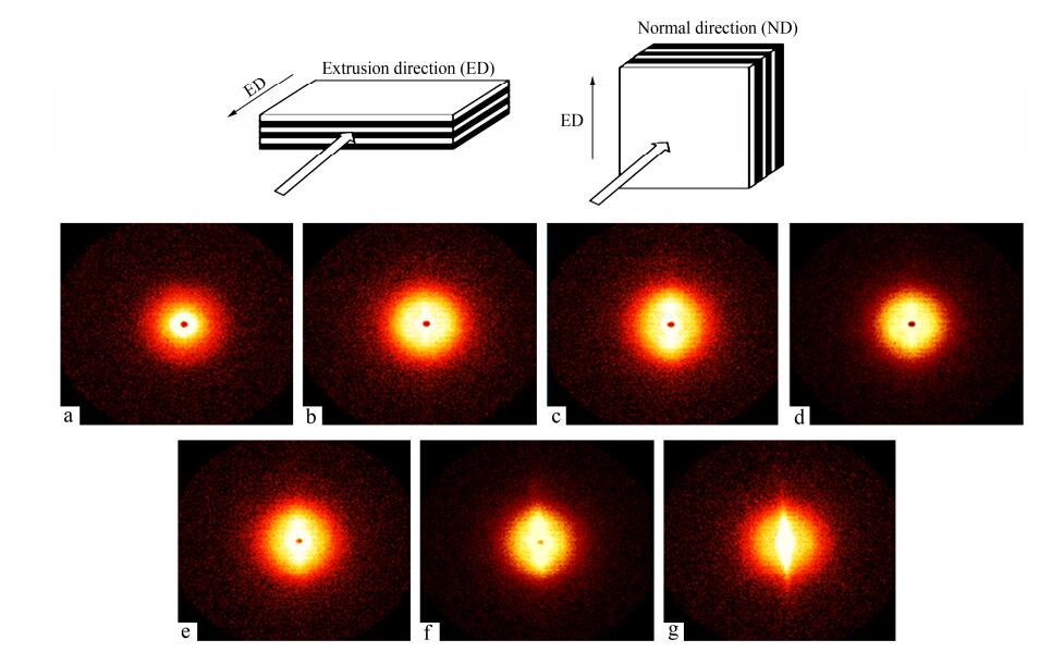 Figure 5.
2D SAXS patterns of LDPE/PS layered films with the following LDPE layer thickness, (a) 75 μm, (b) 12.5 μm, (c) 3 μm, (d) 780 nm, (e) 390 nm, (f) 200 nm, (g) 100 nm (The X-ray beam was aligned along the extrusion direction.)
Figure 5.
2D SAXS patterns of LDPE/PS layered films with the following LDPE layer thickness, (a) 75 μm, (b) 12.5 μm, (c) 3 μm, (d) 780 nm, (e) 390 nm, (f) 200 nm, (g) 100 nm (The X-ray beam was aligned along the extrusion direction.)
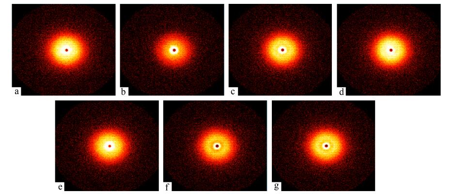 Figure 6.
2D SAXS patterns of LDPE/PS layered films with the following LDPE layer thickness, (a) 75 μm, (b) 12.5 μm, (c) 3 μm, (d) 780 nm, (e) 390 nm, (f) 200 nm, (g) 100 nm (The X-ray beam was aligned along the normal direction.)
Figure 6.
2D SAXS patterns of LDPE/PS layered films with the following LDPE layer thickness, (a) 75 μm, (b) 12.5 μm, (c) 3 μm, (d) 780 nm, (e) 390 nm, (f) 200 nm, (g) 100 nm (The X-ray beam was aligned along the normal direction.)
Unfortunately, the 2D SAXS patterns can only give a qualitative indication of whether the LDPE spherulites or lamellae are isotropic (concentric rings) or are oriented (two-arc or two-spot scattering). The detailed numerical results of the orientation degree cannot be calculated only by the distinguished patterns. In order to analyze the specific crystal accumulation mode and the numerical value of the orientation, the profiles of the scattering vector (q) versus the natural logarithm of the scattering intensity (Fig. 7) and the azimuthal angle versus the intensity (Fig. 8) are extracted from 2D SAXS patterns in extrusion and normal directions.
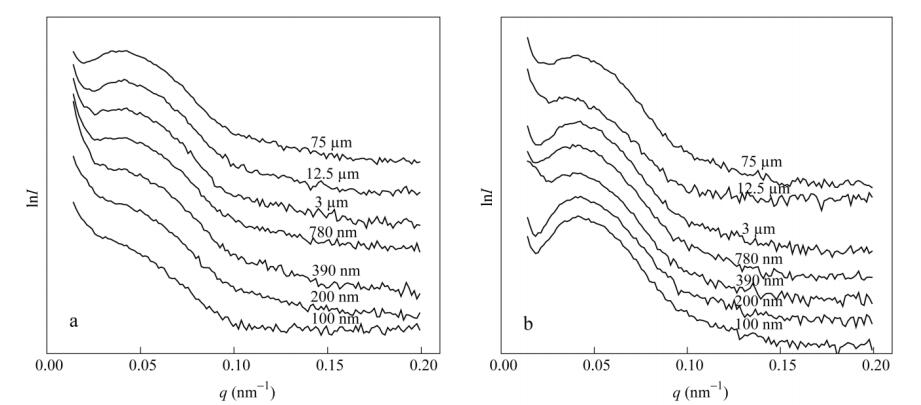 Figure 7.
The meridional SAXS profiles from top to bottom of LDPE/PS layered films with different LDPE layer thickness: 75 μm, 12.5 μm, 3 μm, 780 nm, 390 nm, 200 nm, 100 nm; the profiles are extracted from ED (a) and ND (b) SAXS patterns in Fig. 5 and Fig. 6
Figure 7.
The meridional SAXS profiles from top to bottom of LDPE/PS layered films with different LDPE layer thickness: 75 μm, 12.5 μm, 3 μm, 780 nm, 390 nm, 200 nm, 100 nm; the profiles are extracted from ED (a) and ND (b) SAXS patterns in Fig. 5 and Fig. 6
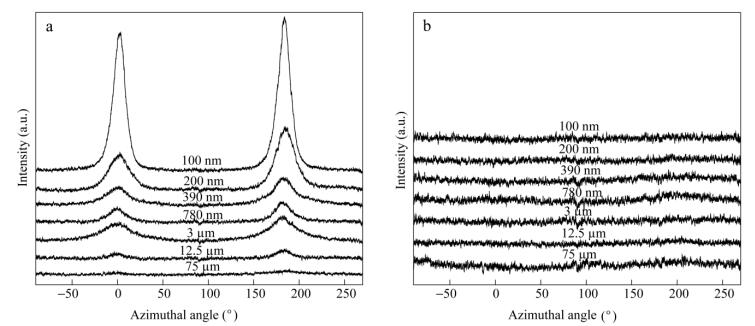 Figure 8.
The azimuthal intensity profiles from top to bottom of LDPE/PS layered films with different LDPE layer thickness: 75 μm, 12.5 μm, 3 μm, 780 nm, 390 nm, 200 nm, 100 nm; the profiles are extracted from ED (a) and ND (b) SAXS patterns in Fig. 6 and Fig. 7.
Figure 8.
The azimuthal intensity profiles from top to bottom of LDPE/PS layered films with different LDPE layer thickness: 75 μm, 12.5 μm, 3 μm, 780 nm, 390 nm, 200 nm, 100 nm; the profiles are extracted from ED (a) and ND (b) SAXS patterns in Fig. 6 and Fig. 7.
In Fig. 7, the first-order peak position q of the LDPE lamellar stacks keeps nearly the same. According to the equationq=2(sinθ)/λ, the scattering vector (q) is related to the scattering angle 2θ and the wavelength θ of X-ray beam. In Fig. 7(a), with the decreases of LDPE layer thickness, the peaks are gradually suppressed. When the LDPE layer thickness is 100 nm, it is much less than the size of LDPE spherulites. The correlated peak in Fig. 7(a) is highly suppressed compared to the other layers. This implies that the stacking of LDPE lamellae is highly confined in the normal direction. On the other hand, the first-order peak in Fig. 7(b) becomes more obvious with decreasing LDPE layer thickness. This implies that the stacking of the lamellae is more easily in the extrusion direction. This phenomenon can support the previous evolution scheme as described in Fig. 3.
The mathematical relation between the azimuthal angle and the scattering intensity is shown in Fig. 8. It can be found that there are two distinct scattering peaks at about 0° and 180° with respect to the X-ray beam direction in Fig. 8(a). Oppositely, the patterns in Fig. 8(b) are almost the same. The peaks in related SAXS patterns all through appear in the extrusion direction relative to LDPE lamellae, which indicates that the lamellae are aligned parallel to the extrusion direction (edge-on).
Herman’s orientation function f is used to calculate the orientation functions of LDPE lamellae, as shown in Eqs. (3) and (4).
The data of Fig. 8(a) can be used in Eq. (4) to calculate cos2θby the numerical integration process. Then the values of cos2θ are used in Eq. (3) to calculate the orientation function value f of the LDPE lamellae. The range of f is between -0.5 and 1, where -0.5 means that the oriented direction is perpendicular to the reference direction, 0 means that the oriented direction is random, and 1 means that the oriented direction is parallel to the reference direction. In other words, the sample is highly oriented when the value of f closes to 1. In Fig. 9, the value of fincreases with decreasing LDPE layer thickness. Furthermore, the value of f slightly increases for thickness between 75 and 3 μm, and suddenly rises between 780 and 100 nm. From the 2D SAXS analysis, it is obvious that the lower LDPE layer thickness is promoted to higher orientation of LDPE lamellae. This phenomenon agrees well with the previous mechanical properties and optical microscope analysis.
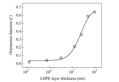 Figure 9.
Effect of LDPE layer thickness on the orientation function (f) of LDPE lamellae by 2D SAXS
Figure 9.
Effect of LDPE layer thickness on the orientation function (f) of LDPE lamellae by 2D SAXS
CONCLUSIONS
The microlayer coextrusion was used to create multilayered films with different numbers of alternating layers of two polymers. The orientation of a polymer in the confined two-dimensional space can be studied by decreasing layer thickness (increasing layer numbers) from microscale to nanoscale. The orientation of LDPE crystalline region can be confined between PS layers from microscale to nanoscale. The SEM images indicate that all the layers are clear and continuous, and the actual layer thickness is similar to the calculated thickness. With the decrease of LDPE layer thickness, the crystal morphology of LDPE is changed from 3D spherulites, 2D spherulites, to stacked edge-on lamellar, and finally to single edge-on lamellar. The transformation of the LDPE crystals can also be observed through POM micrographs. The LDPE lamellae orientation would significantly improve the tensile strength of LDPE/PS films when the layer thickness is reduced to nanosize. 2D SAXS is a useful method for measuring the LDPE lamellae orientation and stacking degree in confined space. Herman's orientation function f can be calculated from 2D SAXS patterns. In order to verify the other previous analysis, the infrared dichroism was used to measure the orientation function of LDPE crystals in the extrusion direction. The abrupt transition of LDPE crystals orientation degree in the extrusion direction can be observed in the stage between microscale (3 μm) and nanoscale (780 nm), and almost no orientation in the normal direction exists.
-
-
[1]
Jin, Y., Rogunova, M., Hiltner, A., Baer, E., Nowacki, R., Galeski, A. and Piorkowska, E., J. Polym. Sci., Part B:Polym. Phys., 2004, 42(18):3380 doi: 10.1002/(ISSN)1099-0488
-
[2]
Liu, X.B., Zhao, Y.F., Fan, X.H. and Chen, E.Q., Chinese J. Polym. Sci., 2013, 31(6):946 doi: 10.1007/s10118-013-1285-9
-
[3]
He, Y.N., Liu, X., Liao, Q., Zhou, J.J., Huo, H. and Li, L., Chinese J. Polym. Sci., 2014, 32(9):1253 doi: 10.1007/s10118-014-1504-z
-
[4]
Yamauchi, Y., Suzuki, N., Radhakrishnan, L. and Wang, L., Chem. Rec., 2009, 9(6):321 doi: 10.1002/tcr.v9:6
-
[5]
Chen, W., Li, X.Y., Liu, Y.P., Li, J., Zhou, W.M., Chen, L. and Li, L.B., Chinese J. Polym. Sci., 2015, 33(4):613 doi: 10.1007/s10118-015-1613-3
-
[6]
Chai, L.G., Zhou, H.X., Sun, X.L., Lia, H.H., Yan, S.K. and Yang, X.Q., Chinese J. Polym. Sci., 2016, 34(4):513 doi: 10.1007/s10118-016-1770-z
-
[7]
Ikeda, T., J. Mater. Chem., 2003, 13(9):2037 doi: 10.1039/b306216n
-
[8]
Yazyev, O.V. and Chen, Y.P., Nat. Nanotechnol., 2014, 9(10):755 doi: 10.1038/nnano.2014.166
-
[9]
Peng, H.S., J. Am. Chem. Soc., 2008, 130(1):42 doi: 10.1021/ja078267m
-
[10]
Carr, J.M., Langhe, D.S., Ponting, M.T., Hiltner, A. and Baer, E., J. Mate. Res., 2012, 27(10):1326 doi: 10.1557/jmr.2012.17
-
[11]
Pu, H.T., Chen, Y.H., Tang, Z.X. and Xu, X.M., Polym. Int., 1997, 44:156 doi: 10.1002/(ISSN)1097-0126
-
[12]
Wang, Z., Xie, X.M., Yang, R. and Wang, X.F., Chem. J. Chin. Univ.-Chin., 2006, 27(1):161
-
[13]
Wang, H., Keum, J.K., Hiltner, A. and Baer, E., Macromolecules, 2009, 42(18):7055 doi: 10.1021/ma901379f
-
[14]
Hamley, I.W., Fairclough, J.P.A., Ryan, A.J., Bates, F.S. and Andrews, E.T., Polymer, 1996, 37(19):4425 doi: 10.1016/0032-3861(96)00261-3
-
[15]
Chambon, F. and Srinivas, S., J. Plast. Film. Sheeting, 1999, 15(4):297 doi: 10.1106/63LC-9M65-GF3X-6PDR
-
[16]
Zhang, C.H., Zhang, Q., Chen, R.F. and Chen, F., Chinese J. Polym. Sci., 2011, 29(4):497 doi: 10.1007/s10118-011-1059-1
-
[17]
Nowacki, R., Kolasinska, J. and Piorkowska, E., J. Appl. Polym. Sci., 2001, 79(13):2439 doi: 10.1002/(ISSN)1097-4628
-
[18]
Zhang, Y., Mukoyama, S., Hu, Y., Yan, C., Ozaki, Y. and Takahashi, I., Macromolecules, 2007, 40(11):4009 doi: 10.1021/ma070021e
-
[19]
Durell, M., Macdonald, J.E., Trolley, D., Wehrum, A., Jukes, P.C., Jones, R.A.L., Walker, C.J. and Brown, S., Europhys. Lett., 2002, 58(6):844 doi: 10.1209/epl/i2002-00451-1
-
[20]
Muratoglu, O.K., Argon, A.S. and Cohen, R.E., Polymer, 1995, 36(11):2143 doi: 10.1016/0032-3861(95)95289-D
-
[21]
Sutton, S.J., Izumi, K., Miyaji, H., Miyamoto, Y. and Miyashita, S., J. Mater. Sci., 1997, 32(21):5621 doi: 10.1023/A:1018688827486
-
[22]
Bu, Z.Z., Yoon, Y., Ho, R.M., Zhou, W.S., Jangchud, I., Eby, R.K., Cheng, S.Z.D., Hsieh, E.T., Johnson, T.W., Geerts, R.G., Palackal, S.J., Hawley, G.R. and Welch, M.B., Macromolecules, 1996, 29(20):6575 doi: 10.1021/ma9603793
-
[23]
Schonherr, H. and Frank, C.W., Macromolecules, 2003, 36(4):1188 doi: 10.1021/ma020685i
-
[24]
Ho, R.M., Lin, F.H., Tsai, C.C., Lin, C.C., Ko, B.T., Hsiao, B.T. and Sics, I., Macromolecules, 2004, 37(16):5985 doi: 10.1021/ma0492869
-
[25]
Mareau, V.H. and Prud'homme, R.E., Macromolecules, 2005, 38(2):398 doi: 10.1021/ma0482359
-
[26]
Abe, H., Kikkawa, Y., Iwata, T., Aoki, H., Akehata, T. and Doi, Y., Polymer, 2000, 41(3):867 doi: 10.1016/S0032-3861(99)00231-1
-
[27]
Sun, X.L., Chen, Z., Wang, F., Yan, S. and Takahashi, I., Macromolecules, 2013, 46(4):1573 doi: 10.1021/ma302349a
-
[28]
Li, Q., Zhou, J.D., Chai, L.G., Memon, J., Ren, Z.J., Li, H.H., Sun, X.L. and Yan, S., Polym. Chem., 2014, 5(14):4293 doi: 10.1039/c4py00119b
-
[29]
Zhou, J.D., Gan, H.Y., Ren, Z.J., Li, H.H., Zhang, J.M., Sun, X.L. and Yan, S., Polymer, 2014, 55(22):5821 doi: 10.1016/j.polymer.2014.09.018
-
[30]
Sun, X.L., Pi, F.W., Zhang, J.M., Takahashi, I., Wang, F., Yan, S. and Ozaki, Y., J. Phys. Chem. B, 2011, 115(9):1950 doi: 10.1021/jp110003m
-
[31]
Lu, X.L. and Mi, Y.L., Chinese J. Polym. Sci., 2015, 33(4):607 doi: 10.1007/s10118-015-1612-4
-
[32]
Hu, Z.J., Baralia, G., Bayot, V., Gohy, J.F. and Jonas, A.M., Nano Lett., 2005, 5(9):1738 doi: 10.1021/nl051097w
-
[33]
Zhu, L., Cheng, S.Z.D., Calhoun, B.H., Ge, Q., Quirk, B.R., Thomas, E.L., Hsiao, B.S., Yeh, F.J. and Lotz, B., J. Am. Chem. Soc., 2000, 122(25):5957 doi: 10.1021/ja000275e
-
[34]
Li, Y.J. and Kaito, A., Macromol. Rapid Commun., 2003, 24(3):255 doi: 10.1002/marc.200390037
-
[35]
Mackey, M., Flandin, L., Hiltner, A. and Baer, E., J. Polym. Sci., Part B:Polym. Phys., 2011, 49(24):1750 doi: 10.1002/polb.v49.24
-
[36]
Wang, Y., Chan, C.M., Ng, K.M. and Li, L., Macromolecules, 2008, 41(7):2548 doi: 10.1021/ma7021309
-
[37]
Fan, W.J., Fan, G.Q., Zhang, X.H. and Yang, Z.H., Chinese J. Polym. Sci., 2016, 34(1):88 doi: 10.1007/s10118-016-1731-6
-
[38]
Lai, C.Y., Hiltner, A., Baer, E. and Korley, L.T.J., Acs Appl. Mater. Interfaces, 2012, 4(4):2218 doi: 10.1021/am300240r
-
[39]
Wang, H.P., Keum, J.K., Hiltner, A. and Baer, E., Macromolecules, 2010, 43(7):3359 doi: 10.1021/ma902780p
-
[40]
Bernal-Lara, T.E., Masirek, R., Hiltner, A., Baer, E., Piorkowska, E. and Galeski, A., J. Appl. Polym. Sci., 2006, 99(2):597 doi: 10.1002/(ISSN)1097-4628
-
[41]
Bernal-Lara, T.E., Liu, R.Y.F., Hiltner, A. and Baer, E., Polymer, 2005, 46(9):3043 doi: 10.1016/j.polymer.2005.01.055
-
[1]
-

 扫一扫看文章
计量
- PDF下载量: 0
- 文章访问数: 1149
- HTML全文浏览量: 57
 下载:
下载:
