 Figure 1.
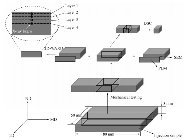
The schematic drawing of sampling methods for each analyzes (MD: flow direction, TD: transverse direction, ND: normal direction.)
Figure 1.
The schematic drawing of sampling methods for each analyzes (MD: flow direction, TD: transverse direction, ND: normal direction.)
Citation:
Man Zhou, Xin-peng Li, Ming Jin, Chao Xia, Kai-zhi Shen, Jie Zhang. Simultaneously Improving the Tensile and Impact Properties of Isotactic Polypropylene with the Cooperation of co-PP and β-nucleating Agent through Pressure Vibration Injection Molding[J]. Chinese Journal of Polymer Science,
2016, 34(8): 1001-1013.
doi:
10.1007/s10118-016-1814-4

Simultaneously Improving the Tensile and Impact Properties of Isotactic Polypropylene with the Cooperation of co-PP and β-nucleating Agent through Pressure Vibration Injection Molding
English
Simultaneously Improving the Tensile and Impact Properties of Isotactic Polypropylene with the Cooperation of co-PP and β-nucleating Agent through Pressure Vibration Injection Molding
Abstract:
In this article, crystalline morphology and molecular orientation of isotactic polypropylene (iPP), random copolymerized polypropylene (co-PP) and β-nucleating agent (β-NA) composites prepared by pressure vibration injection molding (PVIM) have been investigated via polarized light microscopy, scanning electron microscopy, wide-angle X-ray diffraction and differential scanning calorimetry. Results demonstrated that the interaction between co-PP and iPP molecular chains was beneficial for the mechanical improvement and the introduction of β-NA further improved the toughness of iPP. In addition, after applying the pressure vibration injection molding (PVIM) technology, the shear layer thickness increased remarkably and the tensile strength improved consequently. Thus, the strength and toughness of iPP/co-PP/β-NA composites prepared by PVIM were simultaneously improved compared to those of the pure iPP prepared by conventional injection molding (CIM): the impact toughness was increased by five times and tensile strength was increased by 9 MPa. This work provided a new method to further enhance the properties of iPP/co-PP composites through dynamic processing strategy.
-
Key words:
- Mechanical properties
- / Orientation structures
- / Periodical shear field
- / Morphology
-
INTRODUCTION
Isotactic polypropylene (iPP) is one of the most significant polymer materials due to its excellent properties, such as high strength and stiffness, outstanding chemical and moisture resistance, and facile processability[1-3]. Furthermore, iPP is relatively inexpensive compared to other polymer materials. However, the toughness of pure iPP at low temperature is not high enough, which seriously restricts its application as an engineering material[4, 5]. Thus, to promote the toughness of iPP has been widely concerned as a research focus in both academia and industry.
Random copolymerized polypropylene (co-PP) is another most important polypropylene material[6, 7]. It is synthesized by copolymerizing propylene with a small amount of ethylene (usually 1 wt%-5 wt%). The structure of co-PP is similar to iPP. Due to the randomly inserted ethylene units along the main chain, co-PP usually presents a lower melting point and crystallinity compared to iPP. Therefore, co-PP and iPP/co-PP blends are expected to show a better toughness compared to pure iPP[8-11]. Adding β-nucleating agent (β-NA) is another convenient and efficient method to enhance the toughness of iPP[12-14]. However, it would cause the decline of tensile strength as a result of the loose lamellar aggregation of β-PP[15-17]. Up to now, conventional approaches to improve the impact strength of iPP would inevitably deteriorate the tensile strength more or less, thus, new methods should be explored to simultaneously enhance the tensile and impact strength of iPP matrix.
As is well known, the oriented structure can significantly improve the mechanical performance of materials, such as shish-kebab structures[18-20]. Considering the fact that β-crystal can toughen the materials, it is reasonable to figure out a method combining the oriented structure and β-crystal to achieve the simultaneous improvement of tensile strength and impact strength. However, it is difficult for conventional injection molding (CIM) to achieve the mentioned target, because the shear layer of the sample via CIM is very thin and the content of oriented structure is too low to strengthen matrix rigidity[21-23]. In order to further optimize the properties of materials, more highly oriented structures should be formed during the manufacturing processes. Nowadays, a few novel dynamic processing methods have been explored to achieve the above goal, such as dynamic packing injection molding (DPIM)[24, 25], oscillatory shear injection molding (OSIM)[26, 27]. Zhang et al.[28] adopted OSIM technique to manufacture iPP and atactic polypropylene (αPP) blends. Owing to the intense shear field provided by OSIM, there were many oriented structures in OSIM samples compared to the CIM samples. Even though αPP was an adverse factor for the formation of shish-kebabs and crystallization of iPP, the mechanical performance of iPP/αPP OSIM blends improved remarkably compared to those of CIM blends, but the introduction of αPP inevitably deteriorated sort of the intrinsic properties of neat iPP. According to the report by Li et al.[24], the compatibility between the components had an effect on the phase morphology and the orientation of matrix, and since αPP exhibited the better compatibility with iPP, the orientation degree of iPP under shear field decreased compared to those less compatible systems. In other words, new blending systems with appropriate compatibility should be explored to assist iPP matrix to form more oriented structures. Recently, our group has researched on iPP/co-PP systems[11], it is demonstrated that the molecular chain segments of co-PP could entangle with iPP molecular chains and it benefited the crystallization of iPP, the penetration of co-PP molecular chains into iPP crystalline regions facilitated the intermolecular forces, so the mechanical performance of iPP/co-PP was improved in some degree.
As far as we know, there are several reports focusing on the simultaneous improvement of tensile strength and impact strength in iPP parts. However, the mechanism of the simultaneous improvement is still under discussion. Obviously, it is of significant meaning for both academia and industry. Therefore, in this work, we attempt to optimize mechanical properties of iPP with the aid of exerting intense shear field and introducing co-PP and β-nucleating agent to the matrix. Our self-made pressure vibration injection molding (PVIM) equipment which was quite different from the CIM was utilized. The main unique feature of the PVIM technique is that during packing stage the packing pressure can periodically change followed by the piston, namely, a periodical shear field is imposed on the polymer melt and more oriented structures are supposed to be formed consequently. Since co-PP content is reported to be beneficial for the formation of stable oriented structure due to the entanglement between co-PP and iPP molecular chains[29, 30], under intense shear field provided by PVIM, this favorable condition can be fully utilized and more oriented structures are expected to be formed. The introduction of β-NA is designed to obtain more β-crystals which can further improve the toughness of matrix. This study provides a insightful example to simultaneously improve the tensile and impact properties of polymer materials and gives a novel understanding on shear-induced crystallization.
EXPERIMENTAL
Two-dimensional Synchrotron X-ray Scattering
Two-dimensional wide-angle X-ray diffraction (2D-WAXD) measurements were carried out in the Shanghai Synchrotron Radiation Facility (SSRF) instrument. The wavelength of the X-ray was 0.124 nm and the rectangular beam had dimensions of 0.5 mm × 2 mm. A MAR CCD X-ray detector (MARUSA) was employed for detection of 2D-WAXD images, having a resolution of 3072 × 3072 pixels. The distance between sample and detector was 130 mm for WAXD. The sample was mounted on a three-dimensional elevator platform with its thickness direction is parallel to the Y axis. From the skin layer to the core layer, four positions: 0 (layer 1), 500 (layer 2), 1000 (layer 3), 1500 (layer 4) μm down from surface, were scanned, respectively. Finally, Fit-2D and origin software were used to analyze the data. Background for all samples was subtracted before calculation.
Herman's method[31] was used to determine the orientation degree of the lamellar crystals. The Herman's orientation function is defined as:
where cos2φ is an orientation factor defined as
The φ is the angle between the direction of molecular chain and the reference direction (the flow direction); I(f) represents the diffraction intensity. The (040) lattice plane diffraction ring was chosen for calculating the degree of orientation, The values of the orientation parameter f, −0.5, and 1.0, mean perfectly parallel and perpendicular orientation related to flow direction, respectively. For an unoriented sample, f equals 0.
The profiles of 1D-WAXD were obtained from circular integration of intensities of 2D-WAXD patterns. Then, the total crystallinity Xc was calculated by the following equation[32]:
where αcryst and αamorp are the areas of crystalline and amorphous phases, respectively. The relative amount of β-crystals, Kβ, was evaluated using the method of Turner-Jones[33]:
where Iβ1 is the diffraction intensity of the β(300) plane at diffraction angle 2θ=16.1 and Iα1, Iα2 and Iα3 indicate the diffraction intensities of the α(110), α(040) and α(130) planes, at diffraction angles 2θ of 14.1, 16.9 and 18.5, respectively.
Optical Microscopy
A polarizing light microscopy (PLM), DX-1 (produced by JiangXi Phoenix Optical Corporation) was used to observe the microstructure of the sample. The photographs were recorded by a Nikon 500D camera. The sampling method was shown in Fig. 1.
Figure 1.
The schematic drawing of sampling methods for each analyzes (MD: flow direction, TD: transverse direction, ND: normal direction.)
Mechanical Properties Measurement
Tensile tests at room temperature were performed to dumbbell-shaped specimens on a RGT-10 computer controlled electronic universal testing machine under a crosshead speed of 50 mm/min according to ASTM D-638. The Izod notched impact strength was measured with a UJ-40 Izod machine according to ASTM D256-04 and it was also carried out at room temperature. For each measurement five samples were used and the values of all mechanical parameters were calculated as averages.
Materials
Isotactic polypropylene (iPP, trade name T30S) was purchased from Dushanzi Petroleum Chemical Co, with a melt flow rate (MFR) of 2.90 g/10min (230 ℃, 2.16 kg) and density of 0.910 g/cm3. Random copolymerized polypropylene (co-PP, trade name RP2400) was purchased from YUHWA Petroleum Chemical Co. Korea, with a melt flow rate (MFR) of 0.25 g/10min (230 ℃, 2.16 kg), Mw=5.8 × 10⁴ g/mol and 4% the molar fraction of ethylene. The rare earth β-nucleating agent, marked as WBG-Ⅱ, was supplied by Guangdong Foshan Winner Functional Materials, China.
Sample Preparation
To achieve a good dispersion of β-nucleating agent (β-NA) in PP matrix, a two-step process was employed. Namely, a master batch of 5 wt% WBG-II in PP matrix was first prepared by a SHJ-25 co-rotating twin-screw extruder. Then, the master batch was melt blended with pure co-pp and iPP to obtain the corresponding blends. The screw speed was 120 r/min and the temperatures from hopper to die were 150, 170, 180, 200, 200, 200, 200, 200, 190 ℃. The pelletized and dried droplets were then injection-molded into standard dumbbell tensile specimens and rectangular impact specimens for mechanical property tests. The injection temperature was 180, 200, 205 and 205 ℃ from hopper to nozzle and the mold temperature was 40 ℃. As for pressure vibration injection molding, the temperature was set as same as the conventional injection molding, the injection pressure was 27 MPa, the vibration and packing pressure were 65 MPa, the vibration frequency was 0.4 Hz and the packing time was 60 s. More detail information has been described in our previous paper[19, 20]. The as-obtained blends were labeled according to the weight contents of co-PP and β-NA, additionally, there was sign "V" when the sample was prepared by PVIM. For example, iPP/10/0.1-V represented the blend containing 10 wt% co-PP and 0.1 wt% β-NA and was molded by PVIM.
Scanning Electron Microscope
Specimens were cut parallelly to the molding direction and then chemically etched by KMnO4-H2SO4-HNO3-H3PO4 solution at 50 ℃ for 24 h to dissolve away the amorphous phase of the PP matrix. After that, the etched surface was covered with a thin layer of gold by sputtering and observed by a field emission SEM (Inspect-F, Fei, Finland) with an acceleration voltage of 20 kV.
Thermal Behavior
The behavior of samples was carried out by using the TA-Q200 differential scanning calorimeter (DSC) under nitrogen atmosphere. Each sample (around 5 mg) was placed in a sealed aluminum pan. It was first heated to 200 ℃ at the heating rate of 10 K/min and maintained at this temperature for 10 min to erase the thermal history. Then it was cooled down to 40 ℃ at the cooling rate of 10 K/min. Considering the samples exhibit a typical "kin-core" structure as a result of injection process, both the skin and core layer parts were taken for test.
RESULTS AND DISCUSSION
Morphology Investigation
In order to investigate the micro morphology of the blends, the selected samples have been investigated through PLM and SEM.
As fully elucidated in Fig. 3, the CIM samples present a typical "kin-core" structure and the thickness of each layer is quite different. As is known, due to the shear and temperature gradients during the CIM process, skin layer is the out region of sample and presents an anisotropic oriented structure, while core layer is the inner region and always shows an isotropic spherulite structure, as shown in Fig. 3(a). Figure 3(b) presents the morphology of iPP/10 sample, and it's clearly observed that the thickness of skin layer increases as a result of adding co-PP content. Hence, possible conclusion can be obtained that, the entanglement between co-PP and iPP molecular chains is beneficial to the formation of oriented structures. Additionally, the introduction of β-NA can further affect the crystal morphology, as shown in Fig. 3(c), the spherulite size decreases due to the heterogeneous nucleation of β-NA and the thickness of skin layer also increases slightly. It's worth noting that the hierarchy morphology of iPP/10/0.1-V is quite unique, seen in Fig. 3(d). Different from the typical "kin-core" structure in CIM sample, there is another region-hear layer formed in PVIM sample. The other PVIM samples show the similar structures (pictures are not shown here). The thickness of core layer consisting of isotropic spherulite drops unambiguously while the shear layer consisting of highly anisotropic oriented structures becomes dominated. This phenomenon should be owing to the intense shear field provided by the PVIM technology, which could introduce a large amount of shish-kebabs in the inner region of sample. Undoubtedly, this unique hierarchy structure should be responsible for the simultaneous improvement of toughness and tensile strength.
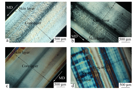 Figure 3.
The PLM observations of (a) iPP, (b) iPP/10, (c) iPP/10/0.1 and (d) iPP/10/0.1-V (MD: flow direction)
Figure 3.
The PLM observations of (a) iPP, (b) iPP/10, (c) iPP/10/0.1 and (d) iPP/10/0.1-V (MD: flow direction)
To obtain a clear observation on the crystalline morphology of samples, the layers observed in PLM were carefully investigated by SEM.
Figure 4 shows the SEM micrographs of CIM samples: iPP, iPP/10, iPP/10/0.1. In the skin layer of the samples, there are fiber-like structures, namely the typical shish-kebab structures, which arrange along the flow direction, according to Figs. 4(a), 4(c) and 4(e). However, there are some differences among them in the core layer. The dominant morphology of iPP is large α spherulites and the interfaces among those spherulites are obvious, indicating a weak interaction force, as shown in Fig. 4(b). Because the addition of small content of co-PP (10 wt%) can obviously influence the crystallization of iPP matrix, as shown in Fig. 4(d), there are many smaller α spherulites well dispersed in the core layer. Possible reasons can be inferred that, the compatibility between iPP and co-PP is favorable, the co-PP molecular chains can run through the iPP matrix as a dispersed phase and form entanglement network, then the entanglement points serve as heterogeneous nucleation sites and many well-dispersed small α spherulites are generated in the core layer. Additionally, when the β-NA is introduced to the iPP/co-PP system, the small but well-developed β spherulites become dominant in the core layer, indicating the heterogeneous nucleation of β-NA, as shown in Fig. 4(f). Those well-developed β spherulites are reasonable for the further improvement of the impact strength of the matrix, while the tensile strength decreases in some degree unavoidably[36-38].
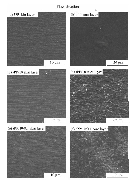 Figure 4.
SEM micrographs of CIM samples: iPP (a, b), iPP/10 (c, d) and iPP/10/0.1 (e, f) (a, c, e: skin layer; b, d, f: core layer)
Figure 4.
SEM micrographs of CIM samples: iPP (a, b), iPP/10 (c, d) and iPP/10/0.1 (e, f) (a, c, e: skin layer; b, d, f: core layer)
Figure 5 presents the SEM images of iPP/10/0.1-V. In accordance with the PLM results, the skin layer and shear layer are both fiber-like structures, which actually compose of many highly oriented crystalline structures. Moreover, it can be easily found that the shish-kebab structures are tighter than those of CIM samples. And unexpectedly, the core layer also shows some oriented structures, even though they are a little disordered. In view of the differences between PVIM and CIM technology, the reasons on the formation of high content oriented structures can be illustrated as follows. During the PVIM processing, strong shear field given by piston moving reversibly is applied to the melt in the mold. As is known, intense shear flow field can facilitate the formation of shish-kebab structures[18, 19]. In this case, owing to the entanglement between co-PP molecular chains and iPP matrix, the oriented structures formed under the intense shear field provided by PVIM technique can be easily remained. Thus there are high content of shish-kebab structures in iPP/10/0.1-V sample, which accounts for the excellent mechanical properties such as tensile strength and impact strength. Unfortunately, the β-PP can not be easily identified in the SEM micrographs. In order to further investigate the crystalline morphology and reveal the role of β-crystals in the reinforcement of iPP matrix, 2D-WAXD and DSC characterizations were further performed in the following parts.
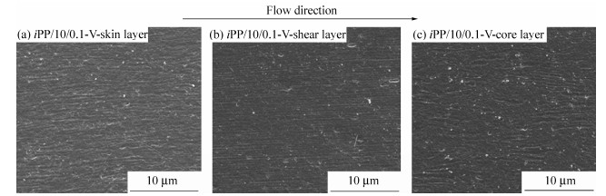 Figure 5.
SEM micrographs of different layers of iPP/10/0.1-V: (a) skin layer, (b) shear layer, (c) core layer
Figure 5.
SEM micrographs of different layers of iPP/10/0.1-V: (a) skin layer, (b) shear layer, (c) core layer
Mechanical Properties
Figure 2 shows the mechanical properties of iPP/co-PP/β-NA blends prepared by CIM and PVIM. As is clearly seen, the impact strength of iPP/10 blends increases from 3.8 kJ/m2 of iPP to 7.5 kJ/m2, while its tensile strength also increases slightly. It is quite agreed with our previous work[11]. In addition, with the introduction of β-NA, the impact strength of iPP/10/0.1 increases from 7.5 kJ/m2 of iPP/10 sample to 12.5 kJ/m2, while the tensile strength of iPP/10/0.1 decreases a little inevitably. These converse variations in mechanical properties are consistent with other literatures[1, 34, 35] and should be contributed to the β-PP induced by β-NA. Most importantly, the iPP/10/0.1-V exhibits superior impact strength and tensile strength. The impact strength reaches 23 kJ/m2, near two times of that of the iPP/10/0.1 (12.5 kJ/m2) and over six times of iPP (3.8 kJ/m2), while the tensile strength goes up from 35 MPa for that of iPP to 44 MPa. For comparison, the mechanical properties of iPP-V and iPP/10-V are also examined. It can be obviously seen that the mechanical properties are improved after applying the PVIM technology. In a word, the PVIM samples exhibit similarly improved tensile strength compared to the CIM samples, and when it comes to toughness, the iPP/10/0.1-V presents the highest impact strength among the samples.
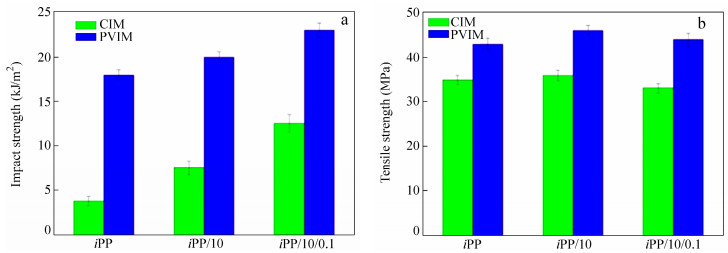 Figure 2.
Comparison of (a) impact strength and (b) tensile strength for iPP, iPP/10, iPP/10/0.1 and iPP/10/0.1-V
Figure 2.
Comparison of (a) impact strength and (b) tensile strength for iPP, iPP/10, iPP/10/0.1 and iPP/10/0.1-V
The simultaneous strengthening and toughening of the iPP/co-PP/β-NA blends have been successfully achieved. The dramatical increases in both impact strength and tensile strength certainly result from the special inner structure caused by the PVIM technology. It's also worth noting that when the periodic shear field is applied, the addition of β-NA does not deteriorate the tensile strength on the one hand, on the other hand, it can further improve the impact strength of the samples. These superior properties inspire us to reveal the structure-property relationship of iPP/co-PP/β-NA blends prepared by PVIM. Hereinafter, we carefully examined the microstructures of the representative samples (iPP, iPP/10, iPP/10/0.1 and iPP/10/0.1-V) via PLM, SEM and 2D-WAXD characterizations.
Thermal Behavior
The thermal behavior of the samples was investigated by DSC. Figure 8(a) shows the melting behaviors of the samples, and iPP exhibits the typical melting behaviors of α-PP with the melt temperature (Tm) of about 168 ℃. For iPP/10 sample, the Tm of α-PP increases, indicating that the introduction of co-PP is beneficial for the stability of α-PP. For the iPP/10/0.1 and iPP/10/0.1-V samples, there is a clearly endothermic peak of β-crystal, suggesting the heterogeneous nucleation effect of β-NA. Moreover, comparing iPP/10/0.1 and iPP/10/0.1-V, it should be noted that the intense shear field has a negative effect on the formation of β-crystal, but there are still some β-crystals in iPP/10/0.1-V and it is in line with the 1D-WAXD results. Figure 8(b) shows the cooling behaviors of samples, and iPP exhibits the crystallization temperature (Tc) of 112 ℃. With the introduction of co-PP, the Tc goes up to 125.5 ℃, suggesting the nucleation effect of co-PP. For the iPP/10/0.1 and iPP/10/0.1-V samples, the addition of β-NA can further improve the Tc, indicating the strong heterogeneous nucleation effect of β-NA for PP crystallization.
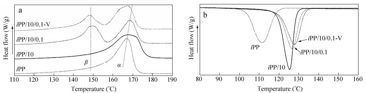 Figure 8.
The DSC curves iPP, iPP/10, iPP/10/0.1 and iPP/10/0.1-V: (a) melting behaviors and (b) crystallization behaviors
Figure 8.
The DSC curves iPP, iPP/10, iPP/10/0.1 and iPP/10/0.1-V: (a) melting behaviors and (b) crystallization behaviors
Crystalline Structure
The crystalline structure was indirectly investigated by 2D-WAXD patterns (Fig. 6) of samples from different layers. All samples basically show five diffraction reflections associated with different lattice planes of iPP, from inner to outer circles, corresponding to (110), (040), (130), (111), and (-131) crystal planes, respectively, which are characteristic of α-crystals. To further understand the crystalline structures of different samples as a function of PVIM and co-PP and β-NA content, 1D-WAXD profiles, obtained by circularly integrating intensities of 2D-WAXD patterns and shown in Fig. 7, were analyzed. The crystallinity (Xc) and the relative crystallinity of β-crystal (Kβ) of samples are also illustrated in Table 1 and Table 2, respectively.
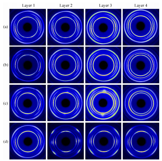 Figure 6.
2D-WAXD patterns of (a) iPP, (b) iPP/10, (c) iPP/10/0.1, and (d) iPP/10/0.1-V From the skin layer to the core layer, four positions: 0 (layer 1), 500 (layer 2), 1000 (layer 3), 1500 (layer 4) μm down from surface, were scanned, respectively.
Figure 6.
2D-WAXD patterns of (a) iPP, (b) iPP/10, (c) iPP/10/0.1, and (d) iPP/10/0.1-V From the skin layer to the core layer, four positions: 0 (layer 1), 500 (layer 2), 1000 (layer 3), 1500 (layer 4) μm down from surface, were scanned, respectively.
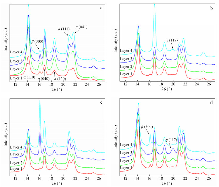 Figure 7.
The 1D-WAXD curves of various samples from surface to core layer: (a) iPP, (b) iPP/10, (c) iPP/10/0.1 and (d) iPP/10/0.1-V
Figure 7.
The 1D-WAXD curves of various samples from surface to core layer: (a) iPP, (b) iPP/10, (c) iPP/10/0.1 and (d) iPP/10/0.1-V
 Table 1.
Crystallinity (Xc) of selected samples obtained from 1D-WAXD analysis
Table 1.
Crystallinity (Xc) of selected samples obtained from 1D-WAXD analysis
Samples Crystallinity Layer 1 Layer 2 Layer 3 Layer 4 iPP 0.49 0.50 0.50 0.52 iPP/10 0.47 0.48 0.49 0.51 iPP/10/0.1 0.49 0.49 0.51 0.52 iPP/10/0.1-V 0.48 0.49 0.50 0.52 Table 1. Crystallinity (Xc) of selected samples obtained from 1D-WAXD analysis
Table 2.
Relative crystallinity of β-crystal (Kβ) obtained from 1D-WAXD analysis
Samples Relative crystallinity Layer 1 Layer 2 Layer 3 Layer 4 iPP 0.018 0.014 0.022 0.012 iPP/10 0 0 0 0 iPP/10/0.1 0 0.047 0.199 0.421 iPP/10/0.1-V 0.012 0 0 0.182 Table 2. Relative crystallinity of β-crystal (Kβ) obtained from 1D-WAXD analysisFor iPP, as shown in Fig. 6(a), the skin layer shows arc-like diffraction of α (040) lattice plane, indicating the presence of oriented structure, while the core layer shows isotropic diffraction circles. A small amount of β-crystals can be found in every layer of iPP, which should be related to weak shear effect in CIM. The iPP/10 sample presents similar diffraction patterns as shown in Fig. 6(b), and more detailed differences can be obtained in 1D-WAXD curves (Fig. 7b): a slight γ (117) peak shows up, which results from the molecular defect caused by the introduction of co-PP. The crystallinity of iPP/10 is almost the same as iPP, which indicates that a small amount of co-PP cannot change the crystallinity significantly. As for iPP/10/0.1, the appearance of (300) lattice planes can be seen obviously in Figs. 6(c) and 7(c), corresponding to the reflection of β-phase. The content of β-crystal increases from layer 1 to layer 4 and reaches the highest value of 0.421 (see Table 2). Moreover, like iPP and iPP/10 samples, the oriented structure only exists in the skin layer, while the core layer exhibits isotropic diffraction circles, indicating random spherulites structure.
However, the iPP/10/0.1-V sample presents completely different patterns (Fig. 6d), and the strong anisotropic diffraction arcs can be seen in every layer from surface to inner region, indicating the existence of highly oriented structures. This phenomenon should be attributed to the intense shear field provided by the PVIM technique which effectively facilitates the formation of oriented crystalline structure on the one hand. On the other hand, the orientation maintenance effect caused by the entanglement between co-PP and iPP molecular chains is also beneficial for the formation of oriented crystalline structure. Due to the strong shear effect provided by the PVIM technology, the content of β-crystal decreases dramatically, especially in the shear layer. However, an obvious β (300) peak in layer 4 still can be found in Fig. 7(d) and the Kβ is 0.182, indicating that there are considerable amounts of β-crystals in the core layer. The β-crystals in the core layer are definitely beneficial to the improvement of toughness of iPP/10/0.1-V. Moreover, the appearance of tiny amount of γ-crystal can be seen in Fig. 7(d), as a result of the intense shear field in PVIM[39, 40].
In order to quantitatively estimate the orientation degree, the orientation parameters (f) for the (040) plane of α-crystal in iPP/10/0.1 and iPP/10/0.1-V were calculated, according to Herman's method[31], and the results are listed in Table 3. For CIM sample (iPP/10/0.1), there is a moderate molecular orientation (the value of orientation parameter is about 0.40) in the skin layer, while the value of orientation parameters decreases dramatically in the core layer, indicating that the orientation degree is very low. However, when the PVIM technique is applied, the orientation degree increases obviously. For iPP/10/0.1-V, every layer shows a higher value of orientation parameters than iPP/10/0.1 sample. The shear layer presents the highest orientation degree, indicating the presence of highly oriented structures, which is well agreed with the SEM results. Even in the core layer, the value of orientation parameters is higher than that of any layer in iPP/10/0.1.
Table 3.
Orientation parameters estimated from azimuthal WAXD patterns of α (040) reflection
Orientation parameters iPP/10/0.1 iPP/10/0.1-V Layer 1 0.3959 0.5364 Layer 2 0.4367 0.6154 Layer 3 0.0685 0.8084 Layer 4 0.0181 0.4937 Table 3. Orientation parameters estimated from azimuthal WAXD patterns of α (040) reflectionMechanism Analysis
The above results demonstrate that our approach can successfully achieve the simultaneous improvement on toughness and tensile properties of iPP/co-PP/β-NA samples. The co-PP content has a significant influence on the crystallization of iPP, due to the randomly inserted small amount of ethylene units, co-PP presents irregular main chains, which will serve as heterogeneous nucleation sites and result in obviously crystal refinement on the one hand. On the other hand, the co-PP molecular chains can entangle with iPP molecular chains[11, 29, 30], which is beneficial to maintain the condensed structure formed in manufacturing process, so the thickness of skin layer increases in some degree, the impact strength and tensile strength also increase slightly. For iPP/10/0.1, when the β-NA was introduced to the matrix, β-spherulite are dominant crystalline form owing to the strong nucleating ability of β-NA, especially in the core layer of sample. The well-developed β-spherulites can be seen in Fig. 4(f). The β-spherulites are basically built by bunched parallel lamellae aggregation, and the bulk spherulite structure is very loose[2, 41]. Therefore, when striking force is applied, lamellae slide is easier to occur, resulting in better impact strength and worse tensile strength. Most importantly, the intense shear field provided by the PVIM technique successfully optimizes the properties of iPP. During the PVIM process, the strong periodic shear field is exerted on the polymer melt and the iPP molecular chain would orderly arrange along the flow direction and forms the so-called shish-kebab structure. Because the shear field would not disappear until the packing stage finished and the molecular chain entanglement cause by co-PP is beneficial to maintain the formed oriented structure[11, 18], there are high contents of oriented structures, confirmed by 2D-WAXD results. As is well known, shish-kebabs as a self-reinforced structure can bring out notable reinforcement on iPP[42, 43], thus, the impact strength and tensile strength increase simultaneously. Moreover, although the β-crystal content decreases as a result of the restrain effect caused by strong shear field[32, 44], there are still some β-crystals in the core layer of iPP/10/0.1-V. Undoubtedly, the inner β-crystals are of great significance to the further improvement of toughness. Like natural plant with a strengthened outer skin and a toughened inner core, such as bamboo, the inner β-crystals form a toughened inner core and play a vital role in force transmission. When the sample suffered the impact force, the inner β-crystals could cause a more serious dissipation of impact energy, thus, the toughness of the sample further improved.
CONCLUSIONS
In this work, simultaneous improvement on toughness and tensile properties of iPP has been successfully achieved by combining the oriented structure via the PVIM processing and addition of co-PP and β-NA. A unique hierarchical structure which included a strengthened outer skin and a toughened inner core was found in the iPP/co-PP/β-NA composites. Namely, the shear layer consisting of rich self-reinforced shish-kebab structure was the strengthened outer skin, while the inner β-crystals formed a toughened inner core. After applying the PVIM technology, the content of shish-kebab structure was dramatically enhanced, while the β-crystals were remarkably restricted, but there were still considerable amounts of β-crystal in the core layer. The impact strength increased remarkably from 3.8 kJ/m2 of pure iPP to 23 kJ/m2, which was improved by nearly five times, meantime, the tensile strength also increased considerably from 35 MPa of pure iPP to 44 MPa. In general, our work provided a new insight into improvement on toughness and tensile properties of modified PP through the new dynamic processing method.
-
-
[1]
Grein C.. in "Intrinsic molecular mobility and toughness of polymers Ⅱ", ed[J]. Berlin Heidelberg Germany, 2005, : 188.
-
[2]
Du, H.N., Zhang, Y., Liu, H., Liu, K.J., Jin, M., Li, X.P. and Zhang, J., Polymer, 2014, 55(19):5001 doi: 10.1016/j.polymer.2014.08.012
-
[3]
Zhang, C.Y., Wang, B., Yang, J.J., Ding, D.W., Yan, X.R., Zheng, G.Q., Dai, K., Liu, C.T. and Guo, Z., Polymer, 2015, 60:40 doi: 10.1016/j.polymer.2015.01.026
-
[4]
Wei, G.X., Sue, H.J., Chu, J., Huang, C. and Gong, K., Polymer, 2000, 41(8):2947 doi: 10.1016/S0032-3861(99)00454-1
-
[5]
Chen, F., Shangguan, Y.G., Jiang, Y.S., Qiu, B.W., Luo, G.H. and Zheng, Q., Polymer, 2015, 65:81 doi: 10.1016/j.polymer.2015.03.064
-
[6]
Gahleitner, M., Jääskeläinen, P., Ratajski, E., Paulik, C., Reussner, J., Wolfschwenger, J. and Neißl, W., J. Appl. Polym. Sci., 2005, 95(5):1073 doi: 10.1002/app.21308
-
[7]
Papageorgiou, D.G., Papageorgiou, G.Z., Bikiaris, D.N. and Chrissafis, K., Eur. Polym. J., 2013, 49(6):1577 doi: 10.1016/j.eurpolymj.2013.02.002
-
[8]
Shao, Y.T., Wu, C.G., Cheng, S.Y., Zhou, F. and Yan, H.B., Polym. Test., 2015, 41:252 doi: 10.1016/j.polymertesting.2014.12.008
-
[9]
Naiki, M., Matsumura, T. and Matsuda, M., J. Appl. Polym. Sci., 2002, 83(1):46 doi: 10.1002/(ISSN)1097-4628
-
[10]
Olley, R.H., Mitchell, G.R. and Moghaddam, Y., Eur. Polym. J., 2014, 53:37 doi: 10.1016/j.eurpolymj.2014.01.010
-
[11]
Jin, B.Q., Li, X.P., Jin, M., Mi, D.S., Wang, F.F. and Xia, C., Chinese J. Polym. Sci., 2016, 34(2):164 doi: 10.1007/s10118-016-1747-y
-
[12]
Liu, Z.Z., Liu, X.H., Zheng, G.Q., Dai, K., Liu, C.T. and Shen, C.Y., J. Mater. Sci., 2015, 50(2):599 doi: 10.1007/s10853-014-8618-0
-
[13]
Liu, X.H., Dai, K., Hao, X.Q., Zheng, G.Q., Liu, C.T., Schubert, D.W. and Shen, C.Y., Ind. Eng. Chem. Res., 2013, 52(34):11996 doi: 10.1021/ie401162c
-
[14]
Mi, D.S., Liu, H., Zhang, L., Wang, T., Zhang, X.W. and Zhang, J., J. Macromol. Sci. B., 2015, 54(11):1376 doi: 10.1080/00222348.2015.1087451
-
[15]
Wang, F.F., Du, H.N., Liu, H., Zhang, Y., Zhang, X.W. and Zhang, J., Polym. Test., 2015, 45:1 doi: 10.1016/j.polymertesting.2015.04.014
-
[16]
Cao, L., Su, D.F., Su, Z.Q. and Chen, X.N., Chinese J. Polym. Sci., 2014, 32(9):1167 doi: 10.1007/s10118-014-1465-2
-
[17]
Dong, M., Guo, Z.X., Su, Z.Q. and Yu, J.A., J. Appl. Polym. Sci., 2011, 119(3):1374 doi: 10.1002/app.v119:3
-
[18]
Somani, R.H., Yang, L., Zhu, L. and Hsiao, B.S., Polymer, 2005, 46(20):8587 doi: 10.1016/j.polymer.2005.06.034
-
[19]
Zhang, Y., Zhang, J., Qian, X.Y., Deng, P. and Shen, K., Polymer, 2012, 53(19):4318 doi: 10.1016/j.polymer.2012.07.013
-
[20]
Mi, D.S., La, R.X., Wang, T., Zhang, X.W. and Zhang, J., Polym. Compos., 2015, DOI: 10.1002/pc.23868
-
[21]
Xu, Z.B., Su, L.Y. and Wang, P.F., Chinese J. Polym. Sci., 2015, 33(8):1114 doi: 10.1007/s10118-015-1663-6
-
[22]
Zhang, J., Guo, C., Wu, X., Liu, F.H. and Qian, X.Y., J. Macromol. Sci. B., 2011, 50(11):2227 doi: 10.1080/00222348.2011.562839
-
[23]
Zhou, Q.X., Liu, F.H., Guo, C., Fu, Q., Shen, K.Z. and Zhang, J., Polymer, 2011, 52(13):2970
-
[24]
Li, J., Zhang, Q., Wang, C., Yang, H., Du, R.N. and Fu, Q., Chinese J. Polym. Sci., 2006, 24(4):379 doi: 10.1142/S0256767906001424
-
[25]
Su, R., Zhang, Z.Q., Gao, X., Ge, Y., Wang, K. and Fu, Q., J. Phys. Chem. B., 2010, 114(31):9994 doi: 10.1021/jp1020802
-
[26]
Chen, Y.H., Fang, D.F., Hsiao, B.S. and Li, Z.M., Polymer, 2015, 60:274 doi: 10.1016/j.polymer.2015.01.058
-
[27]
Chen, Y.H., Huang, Z.Y., Li, Z.M., Tang, J.H. and Hsiao, B.S., RSC Adv., 2014, 4(28):14766 doi: 10.1039/c3ra47990k
-
[28]
Zhang, Z.C., Zhang, R., Huang, Y.F., Lei, J., Chen, Y.H., Tang, J.H. and Li, Z.M., Ind. Eng. Chem. Res., 2014, 53(24):10144 doi: 10.1021/ie5012867
-
[29]
Sheng, B.R., Li, B., Xie, B.H., Yang, W., Feng, J.M. and Yang, M.B., Polym. Degrad. Stab., 2008, 93(1):225 doi: 10.1016/j.polymdegradstab.2007.09.011
-
[30]
Fan, J.S. and Feng, J.C., Ind. Eng. Chem. Res., 2012, 52(2):761
-
[31]
Picken, S.J., Aerts, J., Visser, R. and Northolt, M.G., Macromolecules, 1990, 23(16):3849 doi: 10.1021/ma00218a021
-
[32]
Huo, H., Jiang, S.C., An, L.J. and Feng, J.C., Macromolecules, 2004, 37(7):2478 doi: 10.1021/ma0358531
-
[33]
Turnerjo, A. and Cobbold, A.J., J. Polym. Sci., 1968, 6(8PB):539
-
[34]
Abraham, T., Wanjale, S., Bárány, T. and Karger-Kocsis, J., Composites Part A, 2009, 40(5):662 doi: 10.1016/j.compositesa.2009.03.001
-
[35]
Chen, Y.H., Yang, S., Yang, H.Q., Zhong, G.J., Fang, D.F., Hsiao, B.S. and Li, Z.M., Polymer, 2016, 84:254 doi: 10.1016/j.polymer.2016.01.004
-
[36]
Dong, M., Gu, Z.X., Yu, J. and Su, Z.Q., J. Polym. Sci., Part B:Polym. Phys., 2008, 46(16):1725 doi: 10.1002/polb.v46:16
-
[37]
Su, Z.Q., Chen, X.N., Yu, Z.Z. and Zhang, L., J. Appl. Polym. Sci., 2009, 111(2):786
-
[38]
Dong, M., Guo, Z.X., Yu, J. and Su, Z.Q., J. Polym. Sci., Part B:Polym. Phys., 2009, 47(3):314 doi: 10.1002/polb.v47:3
-
[39]
Su, Z.Q., Wang, H.Y., Dong, J.Y., Zhang, X.Q., Dong, X., Zhao, Y., Han, C.C., Xu, D.F. and Wang, D.J., Polymer, 2007, 48(3):870 doi: 10.1016/j.polymer.2006.12.013
-
[40]
Alamo, R.G., Kim, M.H., Galante, M.J., Isasi, J.R. and Mandelkern, L., Macromolecules, 1999, 32(12):4050 doi: 10.1021/ma981849r
-
[41]
Luo, F., Geng, C.Z., Wang, K., Deng, H., Chen, F., Fu, Q. and Na, B., Macromolecules, 2009, 42(23):9325 doi: 10.1021/ma901651f
-
[42]
Kalay, G. and Bevis, M.J., J. Polym. Sci., Part B:Polym. Phys., 1997, 35(2):241 doi: 10.1002/(ISSN)1099-0488
-
[43]
Schrauwen, B., Breemen, L.V., Spoelstra, A., Govaert, L., Peters, G. and Meijer, H., Macromolecules, 2004, 37(23):8618 doi: 10.1021/ma048884k
-
[44]
Jin, M., Liu, K.J., Liu, H., Zhang, Y., Du, H.N., Li, X.P. and Zhang, J., Polym. Test., 2014, 39(1):e11
-
[1]
-

 扫一扫看文章
计量
- PDF下载量: 0
- 文章访问数: 803
- HTML全文浏览量: 14
 下载:
下载:
