Figure 1.
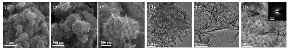
Microstructure and morphology of the F-C sample. (a-c) SEM images; (d, e) TEM images; (f) HRTEM image (inset: SAED pattern).
Mesoporous carbon nanosheet-assembled flowers towards superior potassium storage
Zhang Xianghua , Chen Dong , Zhou Yanping , Yang Dan , Liu Weiling , Feng Yuezhan , Rui Xianhong , Yu Yan

In response to the excessive exploitation of traditional fossil energy and the deterioration of haze environment, it is necessary to carry out the research of renewable energy sources (e.g., solar, ocean and wind energy) [1-4]. Yet the characteristics of instability, randomicity and intermittence of these power have exerted adverse impacts on their further advances. Thus, the development and promotion of large-scale energy storage systems (ESSs) have become of great importance to society [5-8]. As a contemporary popular candidate for ESSs, lithium ion batteries (LIBs) can be successfully applied into this area with prominent advantages of long cycling stability and high energy density [9-12]. Nevertheless, the meager terrestrial reserves of lithium sources limit LIBs application in the long run. Potassium-ion batteries (PIBs) have been recently of great interest to a large number of researchers on account of the rich resources of potassium sources and low working potential of potassium (-2.93 V vs. standard hydrogen electrode (SHE)), closing to that of lithium (-3.1 V vs. SHE), and similar electrochemical chemistry to LIBs [13-16]. However, the larger K-ion (rK+ = 1.38Å) compared to Li-ion (rLi+ = 0.76Å) may cause sluggish ion diffusion, large volumetric expansion and severer structural distortion of the electrode materials during the reversible intercalation/deintercalation [17, 18, 19]. Consequently, seeking super electrode materials is of uppermost priority for PIBs application.
Until now, a large variety of materials such as amorphous carbon [20, 21], graphite [22, 23], phosphorus [24-26] and transition metal oxides [27-29] have been extensively researched as anode materials for PIBs. Among them, carbonaceous materials are considered to be the most promising anodes in terms of high electron conductivity, adjustable microstructure and low cost [30]. To enhance the K-ion storage performance of the carbonaceous anodes, some modification strategies such as designing porous structure with large surface area are proposed [31-33]. A fortified porous carbon frame structure with enlarged surface area and pore volume offers large diffusion channels for rapid mass transport and buffers the huge volume strain, leading to the improved electrochemical performance for PIBs [34-36]. For instance, a porous carbon microsphere with the relative large specific area of 30.7 m2/g and total void volume of 0.12 cm3/g could release a stable specific capacity of 292 mAh/g at 30 mA/g [37]; mesoporous carbon anode (surface area: 64.25 m2/g; pore volume: 0.0349 cm3/g) derived from orange peel exhibited impressive K+ storage property with a specific capacity of 250 mAh/g at 25 mA/g [38]; and a biomass-based hard carbon anode with the surface area of 115 m2/g could deliver a reversible capacity of 262 mAh/g at 30 mA/g [39]. However, their rate capabilities were unsatisfactory, e.g., only 25 mAh/g at 0.5 A/g for the porous carbon microsphere, 123 mAh/g at 0.5 A/g for the mesoporous carbon, and 63 mAh/g at 1.0 A/g for the biomass-based hard carbon. Such inferior rate performance may be caused by the smaller surface area, which affects the electrolyte infiltration and effective transport of K-ions. Therefore, devising and reforming porous carbon anodes with enlarge specific area and increased pore volume are highly demanding for enhanced K-ions storage.
In this work, mesoporous carbon nanosheet-assembled flowers (denoted as F-C) are successfully fabricated and applied as the PIB anode material to demonstrate superior K+ storage performance, e.g., 381 mAh/g at 50 mA/g and 101 mAh/g even at 2.0 A/g, as well as ultralong cycling stability over 600 cycles at 500 mA/g. The favorable PIB characteristics make the F-C sample as the promising potential anode for practical application.
The F-C sample was derived from the acid dissolution of the hierarchical nanosheet-assembled Na3V2(PO4)3@C flowers, as described in our previous work [40]. The morphology and microstructure features of the F-C sample are characterized by SEM and TEM measurements. As revealed in Figs. 1a–c, it is clearly observed that the F-C sample presents uniform submicro-flowers morphology with the sizes of 200−500 nm. TEM images in Figs. 1d and e manifest that the flowers are assembled by ultrathin nanosheets with the thicknesses of around 5 nm. The high resolution TEM (HRTEM) image (Fig. 1f) and its corresponding SAED (selected area electron diffraction) pattern in the illustration of Fig. 1f indicate that the F-C sample is highly disordered amorphous carbon. In comparison, the bulk carbon (denoted as B-C) originated from the bulk Na3V2(PO4)3/C [40], presents irregular bulk morphology with the size distribution ranged from 10 μm to 30 μm (Fig. S1 in Supporting information).
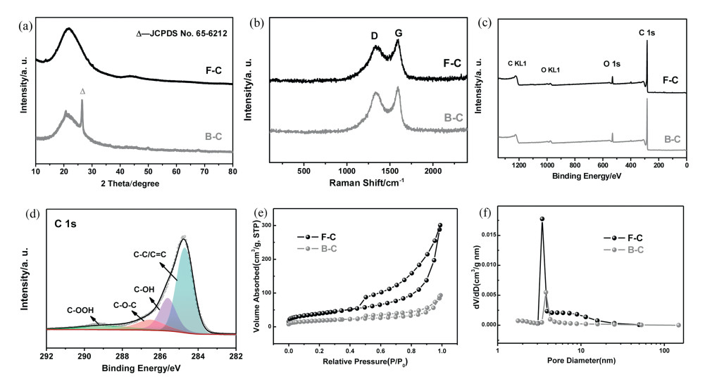
Besides, the F-C and B-C samples are further analyzed by XRD, Raman, XPS, BET, etc. As illustrated in XRD patterns (Fig. 2a), a broad characteristic peak at 2θ of about 21° is attributed to the amorphous carbon for both samples [39, 41]. In addition, a sharp peak at 2θ=26.5° for the B-C sample is assigned to graphitic carbon (JCPDS No. 65-6212), suggesting the presence of some ordered carbon domains. The Raman spectra inFig. 2b show two strong bonds at 1329 and 1592 cm−1, corresponding to the typical disordered band (D-band) derived from the vibration of defect carbon and graphite band (G-band) originated from the in-plane C-C stretching vibration, respectively [42]. The peak intensity ratio (ID/IG) value of the F-C and B-C is almost the same (~0.9), illustrating similar carbon structure with many disordered domains [43, 44]. The XPS spectra inFig. 2c reveal the presence of O and C for both samples. According to Fig. 2d and Fig. S2 (Supporting information), the C 1s core-level XPS spectrum is divided into four independent plateaus with the binding energy of 284.6, 285.6, 286.5 and 288.8 eV, attributing to the C-C/C=C, C-OH, C-O-C and C-OOH bonds, respectively [42]. Accordingly, three independent peaks are also identified to C-OOH (533.5 eV), OH (531.5 eV), and C-OH/C-O-C (532.5 eV) in the O 1s core-level XPS spectra (Fig. S3 in Supporting information) [45-47]. The proportions of these functional groups in the F-C and B-C samples are calculated and shown in Table S1 (Supporting information), in which can be found that the percentage of oxygen-containing groups in F-C sample (~50%) is higher than that in B-C sample (~44.8%). These oxygen species can create some extrinsic favorable defects and active sites to accelerate the absorption and diffusion of K-ions, resulting in a favorable high current charge-discharge ability [48]. Moreover, as shown in Figs. 2e and f, based on Brunauer-Emmett-Teller method, the derived specific area of the F-C sample is estimated to be ~141 m2/g with large pore volume of 0.465 cm3/g and reasonable average pore size of 3.4 nm, which is much higher than that of the B–C sample (65 m2/g).
The electrochemical K-storage properties of the two carbon anodes are measured in the half-cell configuration with the electrolyte of 3 mol/L potassium bis(fluorosulfonyl)imide (KFSI) in 1, 2-dimethoxyethane (DME) and the operational voltage region between 0.01 V and 3.0 V versus K+/K. The CV curves at the scanning rate of 0.1 mV/s are illustrated inFig. 3a. In the first cathodic process, the wide irreversible reduction plateaus located at ~ 1.0 V is originated from the well-distributed formation of a solid-electrolyte interphase (SEI) film [47], while the available peak below 1.0 V may be attributed to the insertion of potassium ions into the F-C anode. In the anodic part, the plateaus situated at about 1.3 V is attributed to the K+ de-insertion, and the plateaus at 1.8–2.6 V is ascribed to the electrochemical reaction, which occurred between the K+ and the oxygen-containing functional groups on the F-C surfaces [49, 50]. The typical galvanostatic discharge-charge potential profiles (current density: 50 mA/g) for the initial three cycles of F-C anode are presented inFig. 3b, which show the well consistency with the above CV results. In the initial discharge stage, a large irreversible capacity (around 1100 mAh/g) and a poor initial Coulombic efficiency (ICE: 26%) are displayed, which are mainly associated with the formation of a SEI film [51]. And the F-C anode exhibits high reversibility of the reactions with high Coulombic efficiency value of > 88% in the subsequent cycles, while the B–C sample shows inferior reversibility with inferior ICE (~22%) and lower CE of ~77% in the subsequent cycles (Fig. S4 in Supporting information). It is mainly due to the smaller surface area and larger size of the B-C sample, which not only causes tardive soaking and penetrating of electrolyte, but also makes the inner of active materials hardly participate in the electrochemical reaction, showing an inferior potassium storage property.Fig. 3c illustrates the cycling capability of the F-C anode at 50 mA/g. It reserves a stable discharge specific capacity of 283 mAh/g and a capacity retention of 74% (estimated based on the 2nd discharge capacity) during the 50th cycle, showing a good cyclic stability. In contrast, the B-C anode shows only 47% capacity retention over 50 cycles at 50 mA/g.
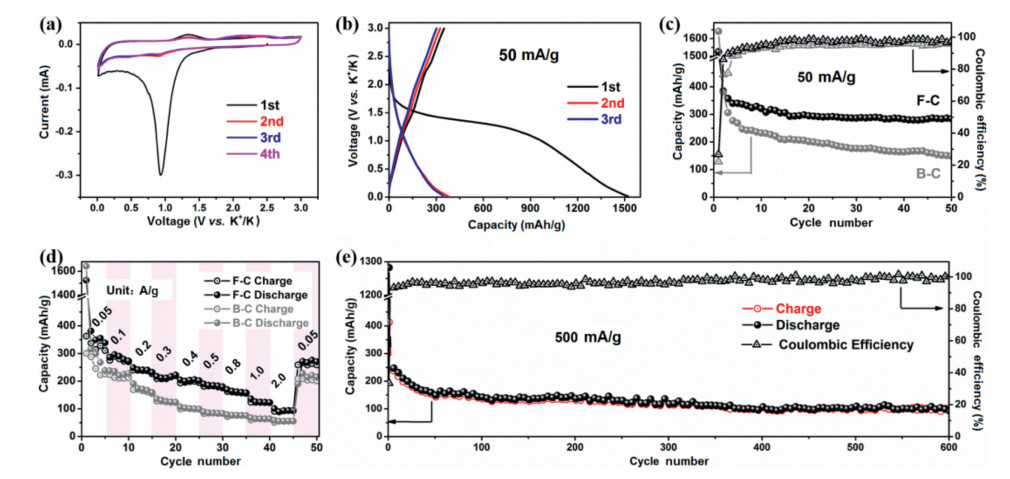
Their rate performances are further studied and presented in Fig. 3d. The F-C anode can deliver discharge capacities of 381, 296, 248, 216, 204, 189, 169, 135 and 101 mAh/g at the current densities of 0.05, 0.1, 0.2, 0.3, 0.4, 0.5, 1.0 and 2.0 A/g, respectively. Meanwhile, the capacity can return to 271 mAh/g when the current density is reverted back to 0.05 A/g, suggesting a fairly outstanding rate property compared to the B-C anode (e.g., 316, 168, 136, 107, 89, 83, 76, 63 and 55 mAh/g at 0.05, 0.1, 0.2, 0.3, 0.4, 0.5, 1.0 and 2.0 A/g, respectively) and recently available carbon anode materials (e.g., 70 mAh/g at 2.0 A/g for hierarchical N-doped carbon nanosheets submicrospheres [52]; and 75.3 mAh/g at 600 mA/g for a low-cost carbon synthesized by acid- and heat-treatment at 1000 ℃ with HNO3) [53]. Besides, the ultra-long cyclability of the F-C anode is also investigated. As shown inFig. 3e, it exhibits robust cycle capability at 500 mA/g with the maintained satisfactory specific capacity of 110 mAh/g after 600 cycles, indicating the extremely steady SEI film and impressively excellent reversibility. Instead, the B-C anode suffers from inferior cycling stability with only 21 mAh/g over 200 cycles at 500 mA/g (Fig. S5 in Supporting information).
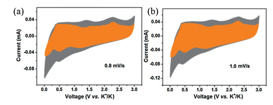
Furthermore, the K+ storage mechanism and kinetics of the F-C anode were examined by the CV technique (scan rates: 0.1–1.0 mV/s). As displayed in Fig. S6a (Supporting information), the CV profiles display similar shapes and gradually increasing peak intensities, in accordance with the previous report [54]. The logi = blogυ+loga [55], is applied to discuss the K+ storage mechanism concerning diffusion and pseudocapacitive contribution. Here, i stands for plateau current, and υ refers to the sweep rate. a and b are treated as constants. Typically, if the b value is 0.5, it implies a total diffusion driven action, whereas b = 1.0 indicates a pseudocapacitive behavior. As illustrated in the Fig. S6b (Supporting information), the b-values of 0.74 and 0.85 for the peaks 1–2 are calculated from the approximate linearity of logi and logυ, suggesting that the K+ storage behavior is mainly synergistically dominated by pseudocapacitive and diffusion effect. Then, the definite contribution of the F-C sample at a given scanning rate is evaluated by the equation of i=k1υ (capacitor-like process) + k2υ1/2 (diffusion-controlled charge behavior) [46]. Figs. 4a and b display the portion of capacitive contribution (orange region) to the total charge storage. On the basis of the calculations, the capacitive contributions of the F-C anode are 71.3% and 74.2% at 0.8 and 1.0 mV/s respectively, illustrating that larger capacitive contribution is conducive to promote a fast K-ions storage kinetics and inspire a high rate capability for F-C electrode.
In summary, a simple synthetic route was put forward to prepare the novel mesoporous carbon nanosheet-assembled flowers, which can primate the fast K-ion diffusion kinetics. As a result, the F-C sample showed splendid electrochemical performances in the matter of high reversible capacity (e.g., 381 mAh/g at 50 mA/g during the 2nd cycle), ultrahigh rate capability (101 mAh/g even at 2.0 A/g) and super stable cycle performance.
The authors declare that they have no known competing financial interests or personal relationships that could have appeared to influence the work reported in this paper.
This work was financially supported by the National Key R & D Research Program of China (No. 2018YFB0905400), National Natural Science Foundation of China (Nos. 51925207, U1910210, 51972067, 61801314, 51802044, 51872277), Guangdong Natural Science Funds for Distinguished Young Scholar (No. 2019B151502039), Sichuan Science and Technology Program (No. 2019YFH0078), Fundamental Research Funds for the Central Universities of China (Nos. WK2060140026 and YJ201703) and the DNL Cooperation Fund, CAS (No. DNL180310).
Supplementary material related to this article can be found, in the online version, at doi:https://doi.org/10.1016/j.cclet.2020.09.025.
X. Xie, S. Liang, J. Gao, et al., Energy Environ. Sci. 13 (2020) 503-510. doi: 10.1039/C9EE03545A
M. Kuang, Y. Wang, W. Fang, et al., Adv. Mater. 32 (2020) 2002189. doi: 10.1002/adma.202002189
C.F. Du, X.L. Sun, H. Yu, et al., InfoMat (2020), doi:http://dx.doi.org/ 10.1002/inf2.12078.
L.Q. Xu, J.Y. Li, Y.T. Li, et al., Chem. Res. Chin. U 36 (2020) 459-466. doi: 10.1007/s40242-020-9088-3
C. Deng, X. Xie, J. Han, et al., Adv. Funct. Mater. 30 (2020) 2000599. doi: 10.1002/adfm.202000599
E.H. Ang, K.N. Dinh, X. Sun, et al., Research (2019) 4029516. http://www.researchgate.net/publication/332824227_Highly_Efficient_and_Stable_Hydrogen_Production_in_All_pH_Range_by_Two-Dimensional_Structured_Metal-Doped_Tungsten_Semicarbides
Y.R. Liang, C.Z. Zhao, H. Yuan, et al., InfoMat 1 (2019) 6-32. doi: 10.1002/inf2.12000
X. Feng, J. He, X. Wang, et al., Chem. Res. Chin. U 34 (2018) 444-450. doi: 10.1007/s40242-018-8003-7
L. Liang, Y. Xu, C. Wang, et al., Energy Environ. Sci. 8 (2015) 2954-2962. doi: 10.1039/C5EE00878F
X. Zhang, D. Yang, X. Rui, Y. Yu, S. Huang, Curr. Opin. Electrochem. 18 (2019)24-30. doi: 10.1016/j.coelec.2019.09.002
Z.Q. Zeng, X.W. Liu, X.Y. Jiang, et al., InfoMat (2020), doi:http://dx.doi.org/ 10.1002/inf2.12089.
W. Luo, X. Cao, S. Liang, et al., ACS Appl. Energy Mater. 2 (2019) 4567-4575.
W. Du, J. Xiao, H. Geng, et al., J. Power Sources 450 (2020) 227716. doi: 10.1016/j.jpowsour.2020.227716
D. Yang, C. Liu, X. Rui, Q. Yan, Nanoscale 11 (2019) 15402-15417. doi: 10.1039/C9NR05588F
S. Yang, Y. Li, Y. Yuan, et al., Chem. Res. Chin. U. 34 (2018) 604-608. doi: 10.1007/s40242-018-8079-0
X. Shi, L. Qin, G. Xu, et al., Chem. Commun. 56 (2020) 3713-3716. doi: 10.1039/D0CC01009J
K. Kubota, M. Dahbi, T. Hosaka, S. Kumakura, S. Komaba, Chem. Rec. 18 (2018) 459-479. doi: 10.1002/tcr.201700057
M. Dahbi, T. Hasegawa, M. Fukunishi, et al., Electrochem. commun. 60 (2016) 172-175.
W. Luo, J. Wan, B. Ozdemir, et al., Nano Lett. 15 (2015) 7671-7677. doi: 10.1021/acs.nanolett.5b03667
W. Hong, Y. Zhang, L. Yang, et al., Nano Energy 65 (2019) 104038. doi: 10.1016/j.nanoen.2019.104038
J. Ge, B. Wang, J. Zhou, et al., ACS Mater. Lett. 2 (2020) 853-860. doi: 10.1021/acsmaterialslett.0c00171
J. Liu, T. Yin, B. Tian, et al., Adv. Energy Mater. 9 (2019) 1900579. doi: 10.1002/aenm.201900579
H.J. Liang, B.H. Hou, W.H. Li, et al., Energy Environ. Sci. 12 (2019) 3575-3584. doi: 10.1039/C9EE02759A
W. Zhang, J. Mao, S. Li, Z. Chen, Z. Guo, J. Am. Chem. Soc. 139 (2017) 3316-3319. doi: 10.1021/jacs.6b12185
I. Sultana, M.M. Rahman, T. Ramireddy, C. Ying, A.M. Glushenkov, J. Mater. Chem. A 5 (2017) 23506-23512. doi: 10.1039/C7TA02483E
Y. Wu, S. Hu, R. Xu, et al., Nano Lett. 19 (2019) 1351-1358. doi: 10.1021/acs.nanolett.8b04957
X.D. He, J.Y. Liao, S. Wang, et al., J. Mater. Chem. A 7 (2019) 27041-27047. doi: 10.1039/C9TA10755J
H. Qiu, L. Zhao, M. Asif, et al., Energy Environ. Sci. 13 (2020) 571-578. doi: 10.1039/C9EE03682B
Z. Liu, P. Li, G. Suo, et al., Energy Environ. Sci. 11 (2018) 3033-3042. doi: 10.1039/C8EE01611A
B. Wang, E.H. Ang, Y. Yang, et al., Chemistry (2020), doi:http://dx.doi.org/ 10.1002/chem.202001811.
X. Zhao, P. Xiong, J. Meng, et al., J. Mater. Chem. A 5 (2017) 19237-19244. doi: 10.1039/C7TA04264G
Y. Sun, H. Xiao, H. Li, et al., Chem. Eur. J. 25 (2019) 7359-7365. doi: 10.1002/chem.201900448
Y. Li, Y. Lu, Q. Meng, et al., Adv. Energy Mater. 9 (2019) 1902852. doi: 10.1002/aenm.201902852
Y. Chen, L. Qin, Y. Lei, et al., ACS Appl. Mater. Interfaces 11 (2019) 45578-45585. doi: 10.1021/acsami.9b14534
C. Chen, Z. Wang, B. Zhang, et al., Energy Storage Mater. 8 (2017) 161-168. doi: 10.1016/j.ensm.2017.05.010
X. Shi, Y. Zhang, G. Xu, et al., Sci. Bull. (2020), doi:http://dx.doi.org/10.1016/j. scib.2020.07.001.
S.H. Choi, J. Baucom, X. Li, et al., J. Colloid Interf. Sci. 577 (2020) 48-53. doi: 10.1016/j.jcis.2020.05.051
R. Verma, Y.N. Singhbabu, P.N. Didwal, et al., Batter. Supercaps (2020), doi:http://dx.doi.org/ 10.1002/batt.202000068.
W. Li, Z. Li, C. Zhang, et al., Solid State Ion. 351 (2020) 115319. doi: 10.1016/j.ssi.2020.115319
Y. Zhou, X. Zhang, Y. Liu, et al., Small 16 (2020)1906669. doi: 10.1002/smll.201906669
Y. Qian, S. Jiang, Y. Li, et al., Energy Storage Mater. 29 (2020) 341-349. doi: 10.1016/j.ensm.2020.04.026
J. Hu, Y. Xie, M. Yin, Z. Zhang, J. Energy Chem. 49 (2020) 327-334. doi: 10.1016/j.jechem.2020.03.005
J. Cao, J. Li, L. Li, et al., ACS Sustain. Chem. Eng. 7 (2019) 10699-10707. doi: 10.1021/acssuschemeng.9b01343
J. Li, J. Cao, X. Li, et al., J. Energy Chem. 55 (2021) 420-427. doi: 10.1016/j.jechem.2020.07.023
Y. Han, T. Li, Y. Li, et al., Energy Storage Mater. 20 (2019) 46-54. doi: 10.1016/j.ensm.2018.11.004
G. Wang, X.H. Xiong, D. Xie, et al., J. Mater. Chem. A 6 (2018) 24317-24323. doi: 10.1039/C8TA09751H
A.K. Nanjundan, R.R. Gaddam, A.H. Farokh Niaei, et al., Batter. Supercaps (2020), doi:http://dx.doi.org/ 10.1002/batt.202000116.
P. Li, J.Y. Hwang, Y.K. Sun, J. Mater. Chem. A 7 (2019) 20675-20682. doi: 10.1039/C9TA08071F
J. Qian, F. Wu, Y. Ye, et al., Adv. Energy Mater. 8 (2018) 1703159. doi: 10.1002/aenm.201703159
Z. Zhang, J. Zhang, X. Zhao, F. Yang, Carbon 95 (2015) 552-559. doi: 10.1016/j.carbon.2015.08.069
L. Tao, L. Liu, R. Chang, et al., J. Power Sources 463 (2020) 228172. doi: 10.1016/j.jpowsour.2020.228172
M. Liu, L. Chang, J. Wang, et al., J. Power Sources 469 (2020) 228415. doi: 10.1016/j.jpowsour.2020.228415
C.X. Zhao, H. Li, Y.J. Zou, et al., Mater. Lett. 262 (2020) 127147. doi: 10.1016/j.matlet.2019.127147
W. Zhao, Y. Shen, H. Zhang, et al., ACS Appl. Mater. Interfaces 12 (2020) 27045-27054. doi: 10.1021/acsami.0c03730
W. Han, D. Chen, Q. Li, et al., J. Power Sources 439 (2019) 227072. doi: 10.1016/j.jpowsour.2019.227072

Figure 1 Microstructure and morphology of the F-C sample. (a-c) SEM images; (d, e) TEM images; (f) HRTEM image (inset: SAED pattern).

Figure 2 Physical and chemical characteristics of the F-C and B-C samples. (a) XRD patterns; (b) Raman spectra; (c) XPS spectra; (d) Core-level XPS spectrum of C 1s; (e) Nitrogen adsorption-desorption isotherms; (f) Pore size distributions.

Figure 3 The electrochemical characteristics of the F-C and B-C anodes. (a) CV profiles of the F-C anode at 0.1 mV/s. (b) Typical galvanostatic charge-discharge curves of the F-C anode. (c) Cycling performance at a low current density of 50 mA/g. (d) Rate capabilities. (e) Long-term cycling performance of the F-C anode at 500 mA/g.

 扫一扫看文章

扫一扫关注我们
 DownLoad:
 下载:
下载:
