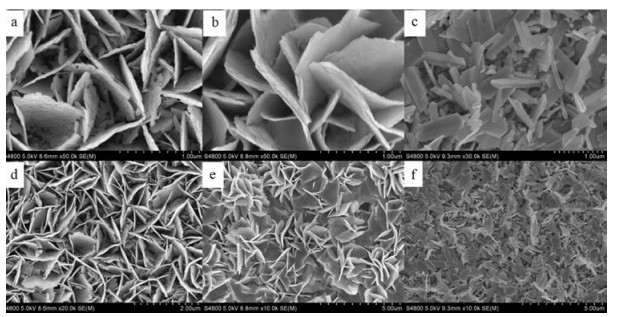
Figure 1.
SEM image of the WO3 film (a and d), photodeposition of MnOx/WO3-P film (b and e), hydrothermal of MnOx/WO3-H film (c and f).
Rationally designed/constructed MnOx/WO3 anode for photoelectrochemical water oxidation
Xiaohu Cao , Xiangyu Zang , Xichen Zhou , Mindong Chen , Yong Ding

Energy is the basic element for the sustainability of human society and it is crucial for social and economic development. Nowadays, owing to the severe environmental pollution, global warming and energy shortage, it is urgent to optimize our existing energy structures, integrate available and potential energy resources to find a way for the future of mankind. Solar energy is a clean and well-stocked energy source, which is the ultimate energy in the existing energy resources that can satisfy our demand of energy [1].
Splitting water to produce hydrogen and oxygen is one convenient way for energy conversion [2]. The water splitting comprises of two half reactions, that is, one is the evolution of O2 (2H2O → O2 + 4H+ + 4e-) and the other is evolution of H2 (4H+ + 4e- → 2H2) [3]. The oxygen evolution reaction involves a process of four-electron transfer, which is more challenging than hydrogen evolution reaction [4].
Since Fujishima et al. [5] discovered that TiO2 can split water under ultraviolet irradiation, many semiconductor materials have been researched for photoelectrochemical water splitting, such as BiVO4 [6-8], Fe2O3 [9-11] and WO3 [12, 13]. WO3 has a bandgap of 2.6–2.7 eV for visible light absorbability, and its valence band position is about 3 V (vs. normal hydrogen electrode (NHE)) to efficiently oxidize water [14]. Therefore, WO3 semiconductor photoanode is chosen by us for researching the water oxidation reaction. However, water oxidation reaction kinetics is sluggish when only WO3 is used as the photoanode. In order to resolve this defect, using cocatalyst is a common strategy to promote the kinetics [15].
Herein, we loaded MnOx on the WO3 photoanode through photodeposition and hydrothermal methods to improve the photoelectrochemical water oxidation performance. Manganese oxide existed on prepared composite photoanode WO3 nanoflakes was confirmed by a series of characterizations. Photoelectrochemical tests illustrated that photodeposited MnOx as the cocatalyst increases the photocurrent density of the photoanode.
All chemicals were analytical grade and were used as purchased without further purification. Double-distilled water (18.2 MΩ cm) for the experiments was attained from a Molecular Lab water purifier. The fluorine-doped tin oxide conductive glass (FTO, Zhuhai Kaivo Optoelectronic Technology Co., Ltd., < 15Ω/sq.) was ultrasonically cleaned with acetone, ethanol and double-distilled water for 30 min each in sequence prior to use.
WO3 film was prepared on FTO conductive glass using a previously reported method [16]. A WO3 seed layer was coated on a FTO conductive glass by spin coating a seed solution. The seed solution was made by dissolving 1.25 g of H2WO4 and 0.5 g of PVA (poly vinyl alcohol, the average polymerization degree was 1750) in 10 mL of 50 wt% H2O2. Then the coated FTO conductive glass was annealed at 500 ℃ for 2 h in air. A H2WO4 solution was prepared for solvothermal preparation, by dissolving 1.25 g of H2WO4 in 30 mL of double-distilled water and adding 10 mL of 50 wt% H2O2 with heating at 95 ℃. The resulting solution was diluted to 0.05 mol/L with double-distilled water. The annealed FTO conduction glass was placed in a 25 mL Teflon-lined stainless steel autoclave with 3 mL of H2WO4 (0.05 mol/L) solution, 0.02 g of oxalic acid, 0.02 g of urea, 0.5 mL of 6 mol/L HCl, and 12.5 mL of acetonitrile. Then the reaction was kept at 180 ℃ for 2 h. After reaction, the FTO conduction glass was washed with double-distilled water and dried at 60 ℃. The resulting WO3 film was annealed at 500 ℃ for 1 h in air.
Hydrothermal of MnOx on WO3 film was carried out hydrothermally starting with solution of MnSO4·H2O and KMnO4 following the procedure reported method [17]. A mixed solution of MnSO4·H2O and KMnO4 was transferred to a Teflon-lined stainless steel autoclave with the WO3-coated FTO conduction glass and kept at 140 ℃. The time for hydrothermal reaction was 2 h, 4 h, 6 h, 8 h, and 10 h. Then the resulting electrode was washed with double-distilled water and followed by air-dried at room temperature. This sample is labeled as MnOx/WO3-H.
Photodeposition of MnOx on WO3 film was performed from an aqueous solution (initial pH 5.1) containing MnSO4 and NaIO3 as precursors under irradiation [18]. In a usual preparation, a typical three electrode cell included a WO3 film as work electrode, a Ag/AgCl reference, and a Pt counter electrode. A LED light source was used to irradiate the WO3 film work electrode. During illumination, WO3 semiconductor produced holes and electrons. Then, Mn2+ ions were oxidized to high valence species, which precipitated on the surface of the WO3 film electrode. This sample is labeled as MnOx/WO3-P.
X-ray diffraction (XRD) measurements were performed on PANalytical X'Pert Pro Diffractometer using Cu-K radiation as the X-ray source. The surface morphologies of the above-mentioned electrode were investigated by scanning electron microscopy (SEM, SU8020) and transmission electron microscopy (TEM, Tecnai G2 TF20). X-ray photoelectron spectroscopy (XPS) spectra were measured by ESCALAB250xi with X-ray monochromatization and the binding energy was calibrated with respect to C 1s level 284.8 eV of contaminated carbon.
Photoelectrochemical measurements were conducted using a three-electrode set up with a Ag/AgCl (3.5 mol/L KCl) as reference, a Pt electrode as a counter electrode. All photoelectrochemical measurements were implemented on a CHI 660D workstation (CH Instruments Co.) under simulated solar light irradiation with an AM 1.5G filter (100 mW/cm2, Perfect Light). Throughout all the experiment, 0.1 mol/L potassium phosphate buffer (pH 7) was used as an electrolyte. All measured potentials were converted to V vs. RHE according to ERHE = EAg/AgCl + 0.208 + 0.059 pH. The photocurrent-potential curves were measured by linear sweep voltammetry with a scan rate of 10 mV/s.
The morphologies of pristine WO3 and MnOx/WO3 were investigated by SEM and TEM. Fig. 1 presents typical SEM images of an illustrative as-prepared WO3 nanoflake, which was grown on a FTO conduction glass substrate. Figs. 1a and d show that WO3 nanoflakes pile up with rough surface, which could increases the contact area between electrode and electrolyte solution. After photodepositing MnOx on WO3 film, the surface of catalyst composite becomes smooth (Figs. 1b and e). It is obvious that nanoflake construct remains after photodeposition process. Unfortunately, hydrothermal deposition of MnOx on WO3 changes WO3 nanoflake structure (Figs. 1c and f) and a great deal of MnOx is found on the surface of the irregular WO3 nanorods.
TEM images were carried out to better illustrate the configurations of the MnOx catalyst on WO3 film. In order to investigate the microstructure of WO3 and MnOx/WO3-P film, TEM measurements were performed on a pristine sample and photodeposited MnOx sample. TEM images show the nanoflake structure of WO3 (Figs. 2a and d) remains unchanged with photodepositing MnOx. The lattice spacing of 0.35 nm is clearly observed, corresponding to the (012) plane of monoclinic WO3 (Fig. 2b). The lattice spacing of 0.32 nm is corresponding to the (201) plane of MnO2 (Fig. 2e), which suggests the formation of MnO2 on the surface of WO3. Furthermore, it can be seen that the electron diffraction spectrum of WO3 is a diffraction spot with certain symmetry (Fig. 2c). While a concentric diffraction ring is observed for the MnOx/WO3-P film (Fig. 2f), indicating that the measured material contains microcrystalline, this can prove that MnOx loaded on the WO3. Energy dispersive X-ray spectroscopy (EDX) characterizations further confirm that the Mn element is present on the WO3 electrode after loading the MnOx catalyst (Fig. S1 in Supporting information).
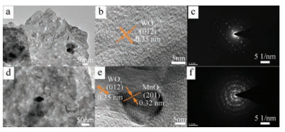
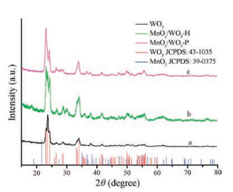
Fig. 3 shows the XRD patterns of the composite photoanodes. The black line is the XRD pattern of pristine WO3 film on FTO conduction glass. The green one is the XRD pattern of MnOx/WO3-H, which was obtained by hydrothermal synthesis method. The pink one is the XRD pattern of MnOx/WO3-P, which was made by photodeposition method. Curve a in Fig. 3 gives diffraction peaks of 23.1°, 23.6°, 24.4°, 34.0°, 41.9°, 49.9° and 55.9°, which are indexed to the (002), (020), (200), (202), (222), (140), and (420) lattice fringe diffractions of the monoclinic WO3 (JCPDS: 43-1035) [19]. Compared with pure WO3, the XRD patterns of the other two composites have changed after loading MnOx catalyst (Fig. 3, curves b and c). The characteristic peak located at 63.1° is indexed to the (511) lattice diffraction of MnO2 (JCPSD: 39-0375). MnOx has been coated on the WO3 photoanode through two different preparation methods, which is consistent with the SEM images. Indeed, MnO2 is detected by XRD and TEM measurements in the composite photoanode. However, due to the very positive potentials of the top of the valence band of WO3, it is possible for the composite photonode to generate some other Mn species with other valence states during the process of preparing MnOx/WO3 and photoelectrochemical test. In addition, we cannot rule out the other manganese oxide species since comparatively limited amount of manganese species loaded on WO3 photoanode is detected hardly. Therefore, MnOx is used in the manuscript instead of MnO2.
From the survey spectrum of WO3 (Fig. S2 in Supporting information), we can see the distinct peaks of W and O elements. The fine W4f spectrum is shown in Fig. S2b. The peaks located at 35.5 eV and 37.6 eV correspond with W 4f7/2 and W 4f5/2 of WO3 [20], respectively. Fig. S2c is the Mn 3s fine XPS spectrum of MnOx/WO3-P, suggesting the successful loading of MnOx on WO3 [21].
In order to evaluate the photoelectrochemical activity of MnOx modified WO3 photoanodes, a three-electrode electrochemical cell using a Pt plate as a counter electrode and a Ag/AgCl (3.5 mol/L KCl) as a reference electrode was set up for implementing linear sweep voltammograms (LSVs). Fig. 4 demonstrates the LSVs of two different ways to load MnOx on WO3 photoanode. The photocurrent density decreases after loading MnOx by hydrothermal synthesis method compared with that of pristine WO3 photoanode (Fig. 4a). After loading MnOx by hydrothermal method, the photocurrent density of the electrode decreases with the time of hydrothermal synthesis. When the hydrothermal time is 10 h, the photocurrent density approaches approximately zero. The onset potentials of composite photoanodes change more positive than that of pristine WO3 photoanode. The main reason for the negative effect is probably that the ordered structure of nanoflake WO3 has changed during the hydrothermal procedure. As displayed in Figs. 1c and f, unordered structure is not conducive to the separation of photogenerated electron-hole pairs. The more time hydrothermal process continues, the more MnOx is loaded on WO3. Over much MnOx can block the incident illumination and decrease the light-absorbed efficiency [10]. In addtiotion, holes are hard to arrive at the interface for oxygen evolution reaction. In all, the activity of composite photoanode MnOx/WO3-H declines due to WO3 structure variation and much loaded MnOx.
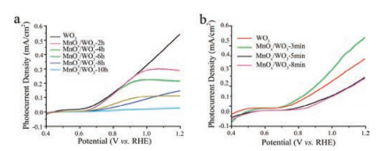
Fig. 4b displays the LSV of the MnOx/WO3-P photoanode produced by photodeposition method. The dependence of photocurrent on deposition time is also studied, and the optimum time of the composite photoanode is 3 min. When the photodeposition time increases, the photocurrent density decreases in the whole test range of potential. In the process of photoelectrochemical water oxidation, holes must be transferred to the interface for oxidizing water and avoid the recombination with electrons [22]. The poor performance of the samples at 5 min and 8 min could be attributed to the accumulation of MnOx among the nanoflakes of pristine WO3, which perhaps aggravates the recombination of electrons and holes. Only suitable amount of MnOx loaded on WO3 can extract holes from WO3 and boost surface reaction kinetics.
In summary, two different methods were used to load MnOx on WO3 photoanode and the photoelectrochemical activity and some characterizations of MnOx/WO3 composite electrodes were carried out. It is found that the activity of WO3 photoanode could be improved efficiently after loading MnOx by photodeposition. The maximum photocurrent density of composite photoanode is achieved with a deposition time of 3 min, which is higher than that of pristine WO3 photoanode around 40%. However, loading MnOx by hydrothermal method will change the original structure of WO3 photoanode and the photoelectrochemical water oxidation performance of WO3 electrode declines after hydrothermal procedure. In a word, photodeposition of cocatalysts MnOx on the surface of WO3 semiconductor can effectively promote photoelectrochemical performance. Our research provides insightful guidelines for designing and synthesizing new efficient photoelectrochemical water oxidation catalysts in the future.
This work was financially supported by the National Natural Science Foundation of China (Nos. 21173105, 21773096), Fundamental Research Funds for the Central Universities (No. lzujbky-2016-k08), Open fund by Jiangsu Key Laboratory of Atmospheric Environment Monitoring and Pollution Control (No. KHK1701) and the Natural Science Foundation of Gansu (No. 17JR5RA186).
Supplementary data associated with this article can be found, in the online version, at https://doi.org/10.1016/j.cclet.2017.12.010.
I. Roger, M.A. Shipman, M.D. Symes, Nat. Rev. Chem. 1(2017) 0003. doi: 10.1038/s41570-016-0003
Y. Feng, J. Wei, Y. Ding, J. Catal. 339(2016) 186-194. doi: 10.1016/j.jcat.2016.04.009
M. Zheng, Y. Ding, L. Yu, X. Du, Y. Zhao, Adv. Funct. Mater. (2017) 1605846. doi: 10.1002/adfm.201605846
X. Du, J. Huang, Y. Feng, Y. Ding, Chin J. Catal. 37(2016) 123-134. doi: 10.1016/S1872-2067(15)61012-9
A. Fujishima, K. Honda, Nature 238(1972) 37-38. doi: 10.1038/238037a0
Y.H. Ng, A. Iwase, A. Kudo, R. Amal, J. Phys. Chem. Lett. 1(2010) 2607-2612. doi: 10.1021/jz100978u
Y. Feng, H. Cheng, J. Han, et al., Chin. Chem. Lett.28(2017) 2254-2258. doi: 10.1016/j.cclet.2017.10.025
R. Li, F. Zhang, D. Wang, et al., Nat. Commun. 4(2013) 1432. doi: 10.1038/ncomms2401
L. He, L. Jing, Y. Luan, L. Wang, H. Fu, ACS Catal. 4(2014) 990-998. doi: 10.1021/cs401122e
J. Huang, G. Hu, Y. Ding, M. Pang, B. Ma, J. Catal. 340(2016) 261-269. doi: 10.1016/j.jcat.2016.05.007
M. Wang, M. Wang, Y. Fu, S. Shen, Chin. Chem. Lett. 28(2017) 2207-2211. doi: 10.1016/j.cclet.2017.11.037
C.A. Bignozzi, S. Caramori, V. Cristino, et al., Chem. Soc. Rev. 42(2013) 2228-2246. doi: 10.1039/C2CS35373C
J. Huang, Y. Ding, X. Luo, Y. Feng, J. Catal. 333(2016) 200-206. doi: 10.1016/j.jcat.2015.11.003
Q. Mi, A. Zhanaidarova, B.S. Brunschwig, H.B. Gray, N.S. Lewis, Energy Environ. Sci. 5(2012) 5694-5700. doi: 10.1039/c2ee02929d
J. Yang, D. Wang, H. Han, C. Li, Acc. Chem. Res. 46(2012) 1900-1909. http://www.ncbi.nlm.nih.gov/pubmed/23530781/
J. Su, X. Feng, J.D. Sloppy, L. Guo, C.A. Grimes, Nano Lett. 11(2011) 203-208. doi: 10.1021/nl1034573
V. Subramanian, H. Zhu, R. Vajtai, P.M. Ajayan, B. Wei, J. Phys. Chem. B 109(2005) 20207-20214. doi: 10.1021/jp0543330
Y. Matsumoto, S. Ida, T. Inoue, J. Phys. Chem. C 112(2008) 11614-11616. doi: 10.1021/jp804625r
J. Huang, Y. Zhang, Y. Ding, ACS Catal. (2017) 1841-1845.
J.Y. Zheng, G. Song, J. Hong, et al., Cryst Growth Des. 14(2014) 6057-6066. doi: 10.1021/cg5012154
Y. Gorlin, T.F. Jaramillo, J. Am. Chem. Soc. 132(2010) 13612-13614. doi: 10.1021/ja104587v
T. Yao, R. Chen, J. Li, et al., J. Am. Chem. Soc. 138(2016) 13664-13672. doi: 10.1021/jacs.6b07188

Figure 1 SEM image of the WO3 film (a and d), photodeposition of MnOx/WO3-P film (b and e), hydrothermal of MnOx/WO3-H film (c and f).

Figure 3 XRD of WO3 film (black, a), hydrothermal of MnOx/WO3-H (green, b), and photodeposition of MnOx/WO3-P (pink, c).

 扫一扫看文章

扫一扫关注我们
 DownLoad:
 下载:
下载:

