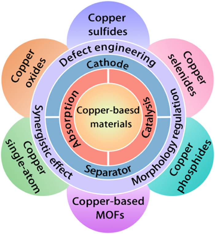
Figure 1.
Schematic of various copper-based materials applied in sulfur cathode and separator.
Recent advances in copper-based materials for robust lithium polysulfides adsorption and catalytic conversion
Fengxing Liang , Yongzheng Zhu , Nannan Wang , Meiping Zhu , Huibing He , Yanqiu Zhu , Peikang Shen , Jinliang Zhu

Li–S batteries are among the most promising second-generation energy storage systems owing to their remarkable energy density and fascinating specific capacity [1–3]. However, the commercialization of Li–S batteries has been hindered by the dissolution of soluble long-chain LiPSs in the electrolyte, which shuttle between the sulfur cathode and lithium anode during cycling, causing the loss of active materials and accelerating capacity decay [4–6]. Numerous efforts have been made to alleviate these issues, including the fabrication of interlayers [7], selection of electrolyte additives [8], modification of separators [9], and the design of multifunctional cathodes [10,11]. Among the various methods, the sulfur cathode and separator play crucial roles in determining the electrochemical performance. Multifunctional sulfur cathodes and separators have been widely used in Li–S batteries since Ji et al. [12] used conductive mesoporous carbon CMK-3 to achieve reversibility and integrity of the sulfur redox reaction. Initially, the physical confinement of various porous carbonaceous materials, such as carbon nanotubes, graphenes, and porous carbon spheres, was extensively studied to preliminarily inhibit the shuttling effect of LiPSs and improve the utilization rate of the active materials [13]. Subsequently, Demir-Cakan et al. [14] found that chemisorption can immobilize LiPSs more effectively than physical confinement. Recently, an adsorption-catalytic conversion strategy has received increasing attention because it facilitates the chemisorption and conversion of LiPSs to Li2S, thereby suppressing the shuttle effect [15].
The transition metal Cu has a high crust abundance, and copper-based materials are rich in lone pair electrons and unfilled d-orbitals, which is beneficial for enhancing their intrinsic catalytic performance by changing the density of electron states, shifting the d-band center, and adjusting the electron spin state [16,17]. Moreover, copper-based materials exhibit excellent physicochemical properties, such as high electrocatalytic activity and high electron conductivity, and have been extensively studied in the fields of energy storage and conversion [18,19]. Copper-based materials have been reported to have a high affinity for LiPSs owing to their lithiophilic/sulphilic sites. In addition, copper-based materials exhibit excellent catalytic activity, which can reduce the energy barrier of redox reactions and thereby accelerate the conversion of LiPSs [20,21]. However, to the best of our knowledge, a comprehensive summary of copper-based materials applied in Li–S battery cathodes and separators has not yet been reported.
In this review, we comprehensively summarize the latest advances in the development of copper-based materials for Li–S batteries (Fig. 1). We focused on exploring the LiPSs adsorption and catalytic conversion of various copper-based materials, including copper oxides, copper sulfides, copper selenides, copper phosphides, copper single-atom, and copper-based MOFs, to gain a deeper understanding of the mechanism of copper-based materials in Li–S batteries. In addition, we introduce three strategies for improving the electrochemical performance of Li–S batteries: defect engineering, morphology regulation, and synergistic effects of different components. Finally, to address the challenges of high-performance Li–S batteries, we provide perspectives for the future development of copper-based materials.
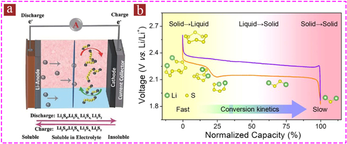
Li–S batteries involve a multistep reversible redox reaction between the sulfur species and lithium metal. During the discharge process, electrons move from the anode to the cathode along the external circuit. Simultaneously, Li+ crosses the separator to the sulfur cathode and interacts with sulfur to form Li2S8, which undergoes solid-liquid conversion. The liquid-phase long-chain Li2S8 is further reduced and converted to short-chain Li2S4 in a liquid-liquid reaction. Li2S4 is then reduced to Li2S2 in a liquid-solid reaction, and finally Li2S2 is converted to Li2S in a solid-solid conversion reaction [22,23]. The charging process is the opposite (Figs. 2a and b). Ideally, the complete discharge process of a Li–S battery should have a theoretically high capacity of 1675 mAh/g. However, long-chain LiPSs dissolve in the electrolyte and migrate from the sulfur cathode to the lithium metal anode owing to concentration polarization, causing the loss of active materials [24–26]. Therefore, the actual capacity of Li–S batteries is lower than the theoretical value.
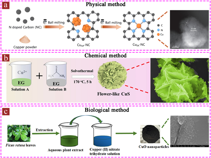
Synthesis methods for copper-based materials are mainly divided into physical, chemical and biological methods. The morphologies and structures of these materials can be synergistically controlled using different synthetic methods.
Ball milling is a versatile approach for synthesizing copper-based materials. It can prepare micron-nanoscale copper oxides and copper single-atom using the high-speed rotation of the container. This rotation causes strong collisions between the particles, agate beads and containers, resulting in a mechanical impact. Henan et al. [27] synthesized copper single-atom via rough two-step ball milling using an N-doped carbon matrix and copper powder (Fig. 3a). By changing the ball milling time during the synthesis process, they were able to regulate the catalytic activity of copper single-atom. The ball milling method has the advantages of adjustable particle size, good operating conditions, and strong adaptability to raw materials. The synthesized copper-based material particles were small and provided more active sites for the adsorption and catalysis of LiPSs. Its shortcomings are low work efficiency and large energy loss.
The flotation method utilizes the hydrophobic properties of copper-containing minerals or the hydrophobic, gas-philic, or oil-philic properties of flotation agents to separate mineral particles into copper-based materials [28–31]. Zhou et al. [32] prepared CuFeS2 from natural chalcopyrite ore using a flotation method. First, natural chalcopyrite ore was crushed and water was added to form the grout. After the grout was diluted and sorted, diesel oil, ethyl flavate and sodium silicate were added as foaming agent, collector, and inhibitor, respectively, and the floating bubbles were collected, concentrated and dried to obtain CuFeS2 powder. Because of the sulphilic characteristics of Cu and Fe, the prepared CuFeS2 effectively captured soluble LiPSs and inhibited shuttle effects. CuFeS2 is a semiconductor with better conductivity than pure sulfur, which can serve as a sulfur source for Li–S batteries and accelerate redox kinetics. The advantages of this method are that it is rich in raw materials and can be used for large-scale production, which meets the low-cost requirements of Li–S batteries. However, its disadvantages include difficulty in process control and the potential for impurity formation.
The hydrothermal/solvothermal reaction method uses water/organic solvents as the solvent and conducts the reaction under specific temperature and autogenous pressure conditions [33,34]. Wu et al. prepared flower-like CuS microspheres using a solvothermal strategy [35]. They separately dissolved CuCl2·2H2O and thiourea (CH4N2S) in ethylene glycol, and the solution was added to a Teflon-lined autoclave and kept at 170 ℃ for 5 h before obtaining flower-like CuS microspheres by washing and drying, as displayed in Fig. 3b. The advantages of hydrothermal/solvothermal method are high crystallinity, purity, and controllable morphology, which can synthesize copper-based materials with different morphologies and structures, thus providing abundant adsorption catalytic sites for physicochemically inhibiting the shuttling of LiPSs. However, a possible disadvantage is the formation of insoluble impurities in the solvent.
Sonochemistry is a method that uses mechanical waves to generate a large number of microbubbles in a liquid: the rapid formation and rupture of microbubbles can generate shock waves and heat in the local space, which further induces redox reactions to synthesize copper-based materials. Seyyedin et al. [36] synthesized CuO nanoparticles loaded on graphene nanosheets (CuO@GO) as the cathode host materials for Li–S batteries using sonochemical technology. First, copper nitrate trihydrate and graphene oxide dissolved in ultrapure water and ultrasonicated. The pH was adjusted to alkaline, and carried out ultrasonic irradiation was performed to obtain CuO@GO nanosheets. Owing to the small particle size and Lewis acidity of CuO, it can improve the catalytic activity and strongly capture LiPSs. The advantages of the sonochemical method include a high synthesis speed and low working temperature. However, a disadvantage is the potential generation of impurity phases in a cascade effect.
During pyrolysis precursors undergo redox reactions at high temperatures to obtain copper-based materials [37,38]. Zhu et al. [39] utilized this method to synthesize Cu3P-Cu2O heterostructures. The process involves the addition of a copper chloride solution to a phosphorus-containing resin, which is then stirred, filtered, and dried to obtain a copper-containing resin. After grinding with KOH, the material was pyrolyzed at 850 ℃ in N2 atmosphere. The resulting product was Cu3P-Cu2O Janus nanoparticles within an N, P co-doped 3D hierarchical porous carbon framework (Cu3P-Cu2O/NPC). Another example of a pyrolysis method was demonstrated by Je et al., where CuS/FeS2@NC was synthesized [40]. Pyrolysis is a simple and effective method to obtain carbon-substrate-loaded copper-based nanomaterials. On the one hand, the carbon framework can load elemental sulfur and physically inhibit the LiPSs shuttle. On the other hand, copper-based materials loaded in the carbon matrix can provide abundant active sites for redox reactions, which can chemically capture LiPSs and catalyze their conversion. However, this is disadvantageous because it consumes more energy and may lead to secondary pollution.
The coprecipitation approach is an important and widely used method for fabricating composite materials containing two or more types of metal elements by adding a precipitating agent to two or more metal salt solutions [41]. Cao et al. [42] employed a coprecipitation method to synthesize a CuO–ZnO bimetallic oxide catalyst. In this method, a certain amount of copper nitrate trihydrate and zinc nitrate hexahydrate were first mixed at an equal Cu/Zn weight ratio and then dissolved in ultrapure water. The mixture was stirred vigorously in a magnetic stirrer at 80 ℃, and NaOH solution was added as the precipitant until the pH reached 9.0. The resulting precipitate was then filtered, washed, and dried. Finally, calcination was performed in air to form a CuO–ZnO heterostructure. The coprecipitation method can be used synthesize uniformly dispersed copper-based heterostructure materials. Multicomponent copper-based materials can realize the adsorption-catalytic conversion of LiPSs. However, the disadvantage of using a precipitant is that it may cause agglomeration or uneven distribution of the components.
Colloidal synthesis refers to the addition of a copper salt into a highly reactive solvent to generate stable colloidal particles and then controlling the particle size, morphology, surface modification and other parameters to synthesize nano-copper-based materials [43–45]. Rachkov et al. [46] synthesized Cu3−xP nanoplatelets by the reaction of tris(diethylamino)-phosphine (P(NEt2)3) with copper chloride (CuCl) in the presence of oleylamine (OAm) and trioctylamine (TOA). Specifically, they first degassed CuCl, OAm, and TOA at 125 ℃ for 3 h, and then rapidly injected P(NEt2)3 under Ar protection at 215 ℃ to obtain Cu3−xP nanoplatelets. Copper-based materials with different morphologies were obtained by simply controlling the reaction temperature and solvent ratio. Its disadvantages include difficulty in large-scale production and the easy generation of toxic gases.
Plant extract-assisted synthesis is a green and cost-effective method for synthesizing copper-based materials, such as copper oxides, copper sulfides, and copper phosphides [47]. The process involved mixing the copper ion-containing solution with a plant extract, adjusting its pH, and incubating, centrifuging, drying, and heat treating, to obtain the final product [48]. Srivastava et al. [49] mixed the aqueous plant extract of ficus retusa leaves with a copper nitrate trihydrate solution to form a paste. After annealing, copper oxide nanoparticles with a size range of 10–15 nm were generated (Fig. 3c). Nano-copper-based materials provide sufficient active sites for LiPSs adsorption. The advantages of plant extract-assisted synthesis include the use of a wide range of raw materials, easy availability and environmental friendliness; however, the process is complex, and may produce impurities.
In vitro and in vivo transformations are the two common methods of microbial transformation. In vitro transformation is a method in which metal ions interact with oxidants or reducing agents secreted by microbial cells, whereas in vivo transformation involves metal ions with redox enzymes in the cytoplasm [50]. Hasan et al. [51] synthesized copper oxide nanoparticles in bacteria by growing them in Luria Bertani Broth medium, and incubating them at 37 ℃ until they reached the stationary phase. CuO and Cu2O nanoparticles with diameters of 10–30 nm were obtained by centrifuging of the supernatants. The synthesis of nanoparticles occurs inside the cell and is then released into extracellular mediators, possibly through intracellular destruction. Although in vivo transformation can produce ultrafine nanoparticles, the synthesis process is difficult to control and its efficiency is low.
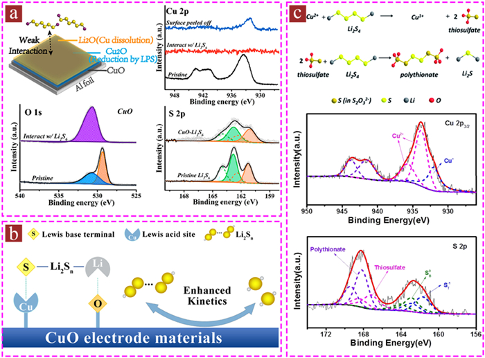
Copper oxide (CuO), a polar surface oxide, is a common type of copper oxides similar to most metal oxides and anchors LiPSs through polar-polar interactions. Surprisingly, Zhong et al. [52] found that CuO underwent a reconstruction phenomenon on its surface after trapping LiPSs, owing to strong chemical interactions (Fig. 4a). Specifically, CuO is first reduced to Cu2O by Li2S6, forming thiosulfate species (S2O32−). Cu2O further reacts with Li2S2O3 to form a soluble Cu(Ⅰ)−thiosulfate complex and an insoluble Li2O layer on the surface. X-ray photoelectron spectroscopy (XPS) analysis of the CuO surface layer before and after interaction with LiPSs revealed that the original CuO was reduced to Cu2O. However, it has also been reported that CuO possesses Lewis acidity because the lowest unoccupied molecular orbit of copper can accept electron pairs [53,54]. During the redox reaction, the Lewis acid site of CuO acts as an electron acceptor and interacts with the Lewis base site of S in LiPSs, which stabilizes the transient states, thereby reducing the conversion energy barrier of the LiPSs and promoting redox kinetics [55], as displayed in Fig. 4b. Li+ in the LiPSs species can also interact with O in CuO, further enhancing chemisorption. These acid-base interactions effectively suppress the shuttle effect of LiPSs and prolong the cycle life of Li–S batteries.
In addition to forming chemical bonds, CuO can also accelerate the conversion of LiPSs by triggering the formation of thiosulfates because the redox potential of CuO is located in the "Goldilocks" voltage window (2.4 V < E0 ≤ 3.05 V), which is just above the redox voltage of LiPSs (2.1 V ≤ E0 ≤ 2.4 V) [56,57]. The highly nucleophilic thiosulfate will attack bridging S(0) in the polysulfides, resulting in soluble "higher-order" Li2Sx polysulfides (x ≥ 4) being catenated into the S–S bond in [O3S-S]2− (thiosulfate) and further forming intermediate surface-bound polythionate complexes [O3S2–(S)x–2–S2O3] and an insoluble "lower order" Li2Sy polysulfide (y < 3), according to Eqs. 1 and 2, respectively:
|
|
(1) |
|
|
(2) |
This is known as the "Wackenroder" thiosulfate mechanism [58]. Inspired by this sulfur chain catenation mechanism, Yang et al. [59] reported that CuO with a redox potential of 2.53 V, could be an efficient material for restricting sulfur and LiPSs in the cathode of Li–S batteries (Fig. 4c). The high-resolution XPS spectra of S 2p and Cu 2p3/2 showed that the Cu in CuO was partially reduced to Cu1+. The S 2p spectra showed two S 2p3/2 contributions at 161.7 and 162.9 eV, which were attributed to terminal ST−1 and bridging sulfur (SB0). The peaks ranging from 166.0 eV to 170.0 eV correspond to the two sulfur environments, at 167.2 eV for thiosulfates and at 168.2 eV for polythionate complexes. The reversible conversion of thiosulfate-polythionate limits the LiPSs to the cathode side and significantly reduces the activity mass loss during the discharging/charging process. Collectively, there are three main explanations for the interaction between CuO and LiPSs, namely surface reconstruction and Lewis acid-base interactions, and thiosulfate−polythionate conversion, of which "Wackenroder" thiosulfate mechanism is widely used.
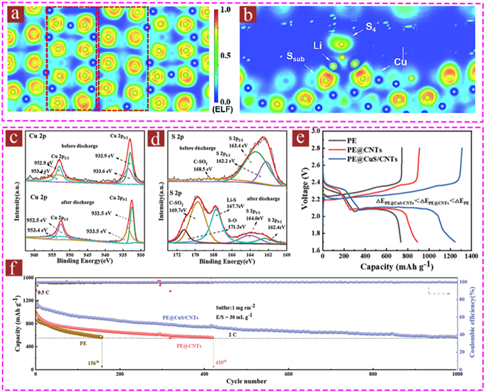
Copper sulfide, which has a strong affinity for LiPSs, is a promising new candidate for controlling the reduction/oxidation reactions of sulfur species in cells [60,61]. It has a specific electronic structure in which the anion S has a lone pair of electrons and the metal cation Cu has an unoccupied d-orbital, which can form strong chemical anchoring effects with Li and S in LiPSs [62,63]. Zhao et al. [64] used density functional theory (DFT) calculations to analyze the interaction mechanism between copper sulfide and LiPSs, and found that the symmetrical arrangement of Cu and S atoms provided abundant active sites that could chemically capture LiPSs and promote fast redox reactions (Fig. 5a). The interaction between copper sulfide and LiPSs was mainly manifested as two-site anchoring, which promoted ion transport, immobilized soluble LiPSs, and maintained the integrity of the Li–S bond fragments (Fig. 5b). Geng et al. [65] conducted a thorough analysis of the chemical interaction between copper sulfide and LiPS species via XPS (Figs. 5c and d) and found that the peaks of both Cu 2p3/2 and Cu 2p1/2 slightly shifted to lower binding energies, while the peaks of S 2p3/2 and S 2p1/2 of CuS shifted to higher energies after discharging, suggesting that the electrons are transferred from polysulfide anions to positive Cu2+, and from S atoms in CuS to Li atoms in LiPSs. The presence of two-site anchoring of copper sulfide in the cathode region effectively restricted shuttling of soluble LiPSs, and as-prepared PE@CuS/CNTs cathode displayed excellent electrochemical properties, with a higher initial discharge capacity and retention capacity of 568.5 mAh/g after 1000 cycles (Figs. 5e and f).
In addition, CuS has good electronic conductivity and a small Li-ion diffusion barrier, which are conducive to accelerated electron transfer and fast Li+ diffusion [66,67]. In addition, CuS is hypothesized to be good capacity-contributing catalyst due to a suitable reaction plateau of 2.1 V, which is very close to the working voltage of Li–S batteries [68]. These properties of copper sulfide make it an ideal candidate for improving the energy density and cycling stability. However, when the discharge voltage is below 1.7 V, copper sulfide undergoes complex secondary reactions, leading to an irreversible phase transition, resulting in capacity degradation upon repeated cycling. Therefore, it will be very intriguing work in the future to clarify the interaction between CuS and LiPSs and the evolution of CuS.
Copper selenides are typical selenides with excellent catalytic properties, and moderate chemisorption capacity, compared to metal oxides and sulfides [69,70]. Benefiting from its lithiophilic/sulphilic sites and excellent electrocatalytic activity, copper selenide can induce uniform Li2S nucleation and fast Li2S dissolution [71]. Wang et al. [72] reported that a graphene-copper selenide heterostructure (Gr-Cu2–xSe@GF) separator achieved polar and catalytic synergies and guaranteed efficient LiPSs adsorption catalysis and rapid and uniform nucleation of Li2S, which alleviated the shuttle effects. Yang et al. [73] prepared defect-rich copper selenide (Cu1.8Se) to investigate the electronic structure of copper selenide, its chemical affinity toward LiPSs adsorption, and how copper vacancies improve the interaction between Cu1.8Se and LiPSs. DFT calculations revealed that defect-rich Cu1.8Se had a much higher binding energy and lower Gibbs free energy change for LiPSs than Cu2Se, revealing that Cu1.8Se exhibits strong adsorption ability and high catalytic activity. Therefore, the defect-rich Cu1.8Se showed better cycle stability than Cu2Se demonstrating an excellent rate performance from 0.1 C to 5 C and maintaining a lifespan of over 1000 cycles at 3 C with a capacity decay rate of only 0.029% per cycle. These results indicate that copper selenide can promote the efficient catalytic adsorption of LiPSs and ensure the rapid and uniform nucleation of Li2S.
In recent years, transition metal phosphides, which possess prominent metallic properties, notable catalytic activity and strong polarity, have attracted significant attention for use in Li–S battery cathodes and separators because they can regulate the entire LiPSs evolution process [74,75]. Based on the multielectron orbitals of phosphorus, metal phosphides can modulate interfacial electron transfer dynamics during electrochemical reactions [76,77]. Compared to metal oxides and sulfides, metal phosphides possess increased energy of bonding states and a reduced energy gap between the bonding and antibonding orbitals because the anion of the P atom is softer and less electron-pulling than O and S atoms, thus facilitating electron transfer to promote the catalytic conversion of LiPSs [78,79]. Inspired by these, Guo et al. [80] innovatively synthesized pollen-derived porous carbon/cuprous phosphide (PC/Cu3P) with pollen as the carbon and phosphorus source as the sulfur host for Li–S batteries. As expected, both the theoretical calculations and the experimental results consistently showed that, the absorption energies of Cu3P toward LiPSs were high and Cu3P had excellent catalytic properties at different temperatures and could stably catalyze the rapid conversion of LiPSs even at 150 ℃. In general, as a host material for Li–S batteries, Cu3P has great potential for regulating the adsorption and catalytic conversion of LiPSs.
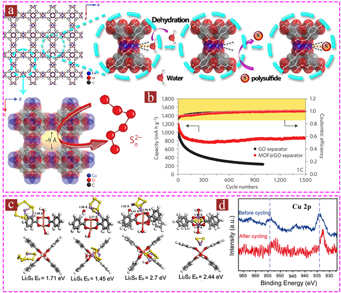
Copper-based metal-organic frameworks (Cu-MOFs) have been extensively used in Li–S batteries owing to their excellent characteristics, such as adjustable porous structures and controllable chemical active sites [81,82]. Taking HKUST as a typical example, which includes a BTC linker and a Cu paddle wheel cluster, two copper atoms were connected to the four carboxylates in BTC and bound to an axial aqua ligand along the Cu-Cu vector [83,84]. Specifically, abundant open Cu sites in HKUST possess Lewis acidity and strong electron electrophilicity and can effectively bind to the electron-rich S sites in LiPSs. The large specific surface area and fine porous structure of HKUST can physically anchor LiPSs. These properties endow HKUST with enhanced adsorptivity and promote the conversion reaction kinetics of LiPSs [85,86]. Benefiting from these advantages, the HKUST-based separator exhibited ultrahigh cycling stability, with a capacity decay rate of 0.019% per cycle over 1500 cycles [87]. Specifically, the water ligand in the coordination center is removed during the redox reaction, and the coordinated unsaturated copper site was exposed. The electron-rich S in LiPSs tends to interact strongly with Cu in MOFs, forming Cu-S bonds, which enhance the chemisorption capacity. In addition, the highly ordered micropores (approximately 9 Å) in HKUST act as an ionic sieve in Li–S batteries, selectively screening lithium ions while blocking undesired LiPSs shuttling to the cathode side (Figs. 6a and b). The chemical anchoring mechanism of LiPSs on HKUST was verified by DFT calculations [88], which showed that polysulfide anions tend to coordinate with the Lewis acid Cu center in HKUST to form Cu-S bonds, providing a strong anchoring ability for LiPSs (Fig. 6c). The XPS spectra before and after the cycle showed that the Cu 2p peak shifted to a lower binding energy after the cycle, confirming a significant chemical interaction between the polysulfide anions and the active sites of Cu in HKUST (Fig. 6d).
Copper single-atom catalysts (Cu-SACs) exhibit a nearly 100% atomic utilization rate, controllable coordination environment and electronic structure. They have been developed as an “emerging catalyst” in Li–S batteries owing to their ultrahigh catalytic activity and moderate adsorption capability [89–91]. Importantly, by manipulating the coordination environment of the Cu metal center, the catalytic activity can be enhanced, thereby improving the kinetics of the redox reaction [92–94].
In order to understand the interaction mechanism of Cu-SACs and LiPSs, Han et al. [95] proposed d-p orbital hybridization theory and divided the orbitals of metal-N4 type Cu-SACs into dz2, dxy, dxz/yz, and dx2-y2. The dz orbital hybridizes with the pz orbital of sulfur to form σ and σ* bonds with strong energy splitting, whereas the dxz/yz orbitals hybridize with the px/y orbitals of sulfur to form two relatively weak π and π* bonds. And dxy and dx2-y2 are usually considered non-bonded because they are not active compared to the other d-states. Xiao et al. [96] showed that SACs-Cu with metal-N4 coordination exhibited strong hybridization between the d orbital of Cu and the p orbital of S; therefore, SACs-Cu had the best catalytic activity. Based on DFT calculations, Gu et al. [97] further explained that the asymmetric coordination Cu-N1C2 single atom had more active sites and a regulated electronic structure, which effectively enhanced LiPSs adsorptivity and promoted the kinetic conversion. As the electrocatalytic centers of LiPSs, Cu-SACs can effectively reduce the energy barrier of LiPSs conversion and have great potential as electrocatalysts for Li–S batteries.
Defect engineering, achieved via heteroatom doping and vacancy formation, is mainly used to tune the local atomic structure and environment of copper-based materials to enhance their electron-transport characteristics [98]. This process can also lead to lattice distortion, localization of the electronic structure, and an increase in the coordination of unsaturated sites, all of which can improve the LiPSs anchoring ability and the reaction kinetics of LiPSs conversion [99]. For example, Pu et al. [100] revealed that the N present in N-CuCo2O4 oxygen vacancies or oxygen lattices is an effective active site that can improve the anchoring ability of LiPSs. Simultaneously, N doping element regulates the electronic structure of CuCo2O4, and the formed metal-N bonds have good conductivity, which promotes the electron transfer and LiPSs redox reaction kinetics. As a result, the as-prepared N–CuCo2O4 cathode delivers a low capacity decay rate of 0.08% per cycle over 300 cycles at 2 C, even with high sulfur loading. However, vacancy formation optimizes the electronic structure of the catalyst and generates abundant unsaturated coordination sites, exhibiting a strong chemical affinity for the LiPSs and lower conversion energy barriers in sulfur reduction reactions, as described by Yang [74]. These results suggest that defect engineering can enhance the chemical adsorption capacity by introducing additional active sites and accelerating the redox kinetics of sulfur conversion by regulating the electronic structure, thereby enhancing the long-term charging/discharging stability under high sulfur loading or high current density.
Customization of the catalyst morphology can expose more redox reaction sites and promote the catalytic conversion of sulfur species. In addition, the same copper-based materials with different morphologies exhibit different interfacial activities and structural characteristics that can physicochemically trap LiPSs. Copper-based materials with fine particle sizes, such as single-atom copper catalysts, can fully contact LiPSs to provide sufficient reactive sites, thereby improving catalytic activity [101]. Nanorod/nanosheet structures have better structural stability than nanoparticles [64,102]. Copper-based materials with three-dimensional structures, such as multilayer porous structures [97], hollow structures [103] and shell-core structures [61], can not only provide abundant active sites, but also improve the loading and immersion efficiency of sulfur and slow down the volume expansion of sulfur during the redox reaction. To sum up, morphological regulation of the copper-based materials can show completely different effects on the adsorption and catalysis of LiPSs.
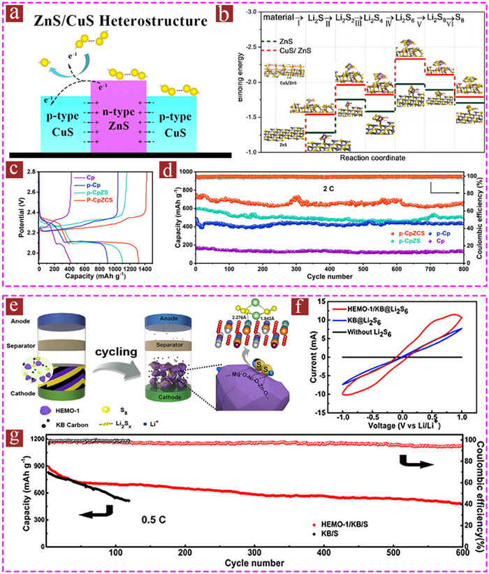
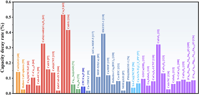
The integration of components with different properties can effectively regulate the rapid conversion of LiPSs. This is due to the synergistic and interfacial effects, which redistribute the charge of the system, accelerate charge transfer and redox reaction kinetics, and provide more active sites for the redox reaction of the sulfur species [104,105]. Moreover, the combination of their respective advantages can maximize the catalytic conversion effect and realize smooth capture-diffusion-conversion of LiPSs across the interface. The heterostructure was a typical multicomponent structure, as reported for ZnS/CuS by Zhai et al. [106]. The dual adsorption of ZnS and CuS enhanced the anchoring effect of LiPSs. The heterointerface formed by n-type ZnS and p-type CuS provides a rapid ion and electron transport channel and promote the rapid conversion of LiPSs to Li2S (Figs. 7a and b). Benefit from the synergistic effect of the two components, the p-CpZCS electrodes delivered greatly improved specific discharge capacities and a smaller polarization potential at 0.1 C, and retained 84.9% discharge capacity after 800 cycles at 2 C (Figs. 7c and d). It has been proven that the addition of a single solid-solution phase composed of five or more metal elements can effectively enhance the interface affinity of LiPSs and significantly improve their adsorption-catalysis properties [107,108]. Moreover, the integration of five metal components (Cu, Mg, Ni, Zn, and Co) to form high-entropy metal oxides (HEMO) exhibited a good catalytic effect and improved the conversion efficiency of LiPSs (Figs. 7e–g) [109]. Multiple studies have also reported the synergistic effect of bimetallic and even trimetallic sulfides, such as CuCo2S4 [110], CuZnS [111], CuSnS2 [112], Cu2ZnSnS4 [113], and Zn0.30Co0.31Cu0.19In0.13Ga0.06S [114] in promoting charge redistribution, accelerating redox reaction kinetics, and improving the electrochemical performance of Li–S batteries. Fig. 8 summarizes the performances of recently reported copper oxides [48,59], copper sulfides [61–64,71,73,97,99,104,115,116], copper selenides [71,73], copper phosphides [80], copper single-atom [96,97], copper-based MOFs [76,85,87,99,117–121] and other copper-based materials [32,100,109,112,113,122–126] in cathodes and separators for Li–S batteries.
Copper-based materials such as copper oxides, copper sulfides, copper selenides, copper phosphides, copper-based MOFs and copper single-atom have been used as sulfur cathodes and separators of Li–S batteries. These materials exhibit strong interactions with LiPSs through an adsorption catalytic-conversion mechanism. Three strategies have been proposed to improve the electrochemical performance of copper-based Li–S batteries: defect engineering, morphology regulation, and the synergistic effect of different components. Although copper-based materials exhibit fascinating electrochemical performance, several challenges must be overcome to fully utilize their potential.
Currently, most studies on copper-based Li–S batteries employ button cells, ignoring the harsh conditions, such as high sulfur loading and low electrolyte/sulfur (E/S) ratio. Generally, increasing sulfur loading and decreasing the E/S ratio blocks electron transport and ion diffusion, resulting in sluggish redox reaction kinetics and a severe shuttle effect. In addition, although copper-based materials have good lithiophilic/sulphilic, which can promote uniform lithium nucleation and accelerate LiPSs conversion, there are few reports on copper-based Li–S full batteries. Based on the detailed molecular mechanism, the dynamic evolution of LiPSs on the surface of copper-based materials remains unclear. To overcome the abovementioned issues, future applications and breakthroughs of copper-based materials in Li–S batteries can be considered from the following perspectives.
(1) Practical application environment: Extensive research has been conducted to achieve excellent specific capacity and cycling stability by controlling the sulfur mass loading to a low level at the laboratory level. However, high sulfur loading and poor electrolyte environment are necessary prerequisites for achieving high energy density and low cost of Li–S batteries. Therefore, it is of great significance to explore the electrochemical performance of copper-based Li–S batteries under high sulfur loading and low E/S ratio.
(2) Construction of full battery: The use of lithiophilic copper-based materials to modify lithium metal anodes can promote the uniform nucleation and growth of lithium and inhibit the formation of dendrites. In addition, copper-based materials have sulphilic and catalytic activities, which show a strong chemical affinity for LiPSs and excellent catalytic ability for the conversion of LiPSs. Therefore, combining their advantages to build a Li–S full battery may be a reasonable approach for improving the overall electrochemical performance.
(3) In situ characterization technologies: The internal reaction mechanism and process of Li–S batteries have always been considered a "black box", and it is extremely important to track the dynamic reaction from the atomic/single molecular scale. Currently, various advanced in situ characterization technologies, such as in situ TEM, in situ UV and in situ XRD, are being used to understand the dynamic reaction process inside Li–S batteries, especially the phase evolution of the catalysts and the deposition and dissolution of LiPSs.
The authors declare that they have no known competing financial interests or personal relationships that could have appeared to influence the work reported in this paper.
This work was supported by the National Natural Science Foundation of China (No. 51962002) and Natural Science Foundation of Guangxi (No. 2022GXNSFAA035463).
X.X. Sun, S.K. Liu, W.W. Sun, et al., Chin. Chem. Lett. 34 (2023) 107501. doi: 10.1016/j.cclet.2022.05.015
Z.H. Yu, X.H. Huang, M.T. Zheng, et al., Adv. Mater. 35 (2023) 2300861. doi: 10.1002/adma.202300861
S. Li, J. Lin, B. Chang, et al., Energy Storage Mater. 55 (2022) 94–104.
Y. Song, M.X. Zhou, Z. Chen, et al., Chin. Chem. Lett. 17 (2023) 109200.
X. Cao, M. Wang, Y. Li, et al., Adv. Sci. 9 (2022) 2204027. doi: 10.1002/advs.202204027
X. Zhang, X. Liu, W. Zhang, et al., Green Energy Environ. 8 (2023) 354–359. doi: 10.1016/j.gee.2022.03.006
Z.H. Liu, X.Q. Mao, S. Wang, et al., Chem. Eng. J. 447 (2022) 137433. doi: 10.1016/j.cej.2022.137433
X.Y. Li, S. Feng, M. Zhao, et al., Angew. Chem. Int. Ed. 61 (2022) e202114671. doi: 10.1002/anie.202114671
W.W. Li, B. Yang, R.X. Pang, et al., Compos. Commun. 38 (2023) 101489. doi: 10.1016/j.coco.2022.101489
J.L. Zhu, X.J. Dong, Q.K. Zeng, et al., Chem. Eng. J. 460 (2023) 141811. doi: 10.1016/j.cej.2023.141811
S.F. Yang, S.P. Luo, X.J. Dong, et al., Nano Res. 16 (2023) 8478–8487. doi: 10.1007/s12274-023-5512-6
X.L. Ji, K.T. Lee, L.F. Nazar, Nature Mater. 8 (2009) 500–506. doi: 10.1038/nmat2460
L. Chen, H. Yu, W.X. Li, et al., J. Mater. Chem. A 8 (2020) 10709–10735. doi: 10.1039/D0TA03028G
R. Demir-Cakan, M. Morcrette, F. Nouar, et al., J. Am. Chem. Soc. 133 (2011) 16154–16160. doi: 10.1021/ja2062659
L.W. Ji, M.M. Rao, H.M. Zheng, et al., J. Am. Chem. Soc. 133 (2011) 18522–18525. doi: 10.1021/ja206955k
T.H. Zhou, W. Lv, J. Li, et al., Energy Environ. Sci. 10 (2017) 1694–1703. doi: 10.1039/C7EE01430A
Z.X. Zhao, Z.L. Yi, Y.R. Duan, Chem. Eng. J. 463 (2023) 142397. doi: 10.1016/j.cej.2023.142397
S.P. Li, Z.L. Han, W. Hu, et al., Nano Energy 60 (2019) 153–161. doi: 10.1016/j.nanoen.2019.03.023
Y.Y. Zhang, Y.L. Sun, L.F. Peng, et al., Energy Storage Mater. 21 (2019) 287–296. doi: 10.1016/j.ensm.2018.12.010
Y.N. Li, N.P. Deng, H. Wang, et al., Electrochim. Acta (2023), doi: 10.1016/j.electacta.2023.143330.
C.L. Wei, B.J. Xi, P. Wang, et al., Adv. Mater. 35 (2023) 2303780. doi: 10.1002/adma.202303780
C.X. Li, Z.C. Xi, D.X. Guo, et al., Small 14 (2018) 1701986. doi: 10.1002/smll.201701986
T. Wang, J.R. He, X.-B. Cheng, et al., ACS Energy Lett. 8 (2023) 116–150. doi: 10.1021/acsenergylett.2c02179
Z.H. Shen, M.Q. Cao, Y. Wen, et al., ACS Nano 17 (2023) 3143–3152. doi: 10.1021/acsnano.2c12436
J.M. Gonçalves, É. A. Santos, P.R. Martins, et al., Energy Storage Mater. 63 (2023) 102999. doi: 10.1016/j.ensm.2023.102999
P.M. Gandhi, S.K. Valluri, M. Schoenitz, et al., Adv. Powder Technol. 33 (2022) 103332. doi: 10.1016/j.apt.2021.10.024
H.N. Xu, L.L. Zhang, H.L. Wang, et al., Chem. Res. Chin. Univ. (2023), doi: 10.1007/s40242-023-2305-0.
F. Jiang, Y.C. Bai, L.M. Zhang, et al., Energy Storage Mater. 40 (2021) 150–158. doi: 10.1016/j.ensm.2021.04.046
Z.H. Zeng, Y. Dong, S.H. Yuan, et al., Energy Storage Mater. 45 (2022) 442–464. doi: 10.1016/j.ensm.2021.11.051
J.H. Zhou, F. Jiang, S.J. Li, et al., J. Solid State Electrochem. 23 (2019) 1991–2000. doi: 10.1007/s10008-019-04284-8
X. Gao, F. Jiang, Y. Yang, et al., ACS Appl. Mater. Interfaces 12 (2020) 2432–2444. doi: 10.1021/acsami.9b17952
J.H. Zhou, S.J. Li, W. Sun, et al., Inorg. Chem. Front. 6 (2019) 1217–1227. doi: 10.1039/C9QI00054B
X. Wang, G. Xu, Z.W. Zhou, et al., J. Porous Mater. 30 (2023) 1295–1302. doi: 10.1007/s10934-023-01423-5
J.J. Jiang, F.J. Zhang, C. Liu, et al., Solid State Sci. 139 (2023) 107165. doi: 10.1016/j.solidstatesciences.2023.107165
Y. Wu, Y. Zhao, M. Zhou, et al., Nano Micro Lett. 14 (2022) 171. doi: 10.1007/s40820-022-00906-5
S.T. Seyyedin, M.R. Sovizi, M.R. Yaftian, Chem. Pap. 70 (2016) 1590–1599.
J.L. Zhu, Q.L. Wu, J.L. Key, et al., Energy Storage Mater. 15 (2018) 75–81. doi: 10.1016/j.ensm.2018.03.014
Y.Y. Qiu, F. Fu, M. Hu, et al., Chem. Eng. J. 454 (2023) 140402. doi: 10.1016/j.cej.2022.140402
J.L. Zhu, E.J. Jiang, X.Q. Wang, et al., Chem. Eng. J. 427 (2022) 130946. doi: 10.1016/j.cej.2021.130946
J. Je, H. Lim, H.W. Jung, et al., Small 18 (2022) 2105310. doi: 10.1002/smll.202105310
M. Du, P.D. Geng, C.X. Pei, et al., Angew. Chem. Int. Ed. 61 (2022) e202209350. doi: 10.1002/anie.202209350
C.Q. Cao, Y.P. Xie, Y. Chen, et al., Ind. Eng. Chem. Res. 60 (2021) 7033–7042. doi: 10.1021/acs.iecr.1c00963
R.W. Lord, J. Fanghanel, C.F. Holder, et al., Chem. Mater. 32 (2020) 10227–10234. doi: 10.1021/acs.chemmater.0c04058
Z. Hu, R. O’Neill, R. Lesyuk, et al., Acc. Chem. Res. 54 (2021) 3792–3803. doi: 10.1021/acs.accounts.1c00209
H. Wang, Q. Liu, W. Li, et al., ACS Nano 10 (2016) 3606–3613. doi: 10.1021/acsnano.5b08079
A.G. Rachkov, A.M. Schimpf, Chem. Mater. 33 (2021) 1394–1406. doi: 10.1021/acs.chemmater.0c04460
M. Nasrollahzadeh, F. Ghorbannezhad, Z. Issaabadi, et al., Chem. Rec. 19 (2019) 601–643. doi: 10.1002/tcr.201800069
R. Hazrati, N. Zare, R. Asghari, et al., Appl. Microbiol. Biotechnol. 106 (2022) 6017–6031. doi: 10.1007/s00253-022-12107-6
V. Srivastava, A.K. Choubey, J. Mol. Struct. 1242 (2021) 130749. doi: 10.1016/j.molstruc.2021.130749
Y. Kato, M. Suzuki, Crystals 10 (2020) 589. doi: 10.3390/cryst10070589
S.S. Hasan, S. Singh, R.Y. Parikh, et al., J. Nanosci. Nanotechnol. 8 (2008) 3191–3196. doi: 10.1166/jnn.2008.095
Y.R. Zhong, K.R. Yang, W. Liu, et al., J. Phys. Chem. C 121 (2017) 14222–14227. doi: 10.1021/acs.jpcc.7b04170
J.N. Wei, T. Wang, X.J. Cao, et al., Appl. Catal. B 258 (2019) 117793. doi: 10.1016/j.apcatb.2019.117793
X.Y. Li, S. Feng, C.X. Zhao, et al., J. Am. Chem. Soc. 144 (2022) 14638–14646. doi: 10.1021/jacs.2c04176
J.C. Ye, J.J. Chen, R.M. Yuan, et al., J. Am. Chem. Soc. 140 (2018) 3134–3138. doi: 10.1021/jacs.8b00411
X. Liang, C.Y. Kwok, F.L. Marzano, et al., Adv. Energy Mater. 6 (2016) 150636.
X.D. Hong, R. Wang, Y. Liu, et al., J. Energy Chem. 42 (2020) 144–168. doi: 10.1016/j.jechem.2019.07.001
X. Liang, C. Hart, Q. Pang, et al., Nat. Commun. 6 (2015) 5682. doi: 10.1038/ncomms6682
Y.X. Yang, Z.H. Wang, G.D. Li, et al., J. Mater. Chem. A 5 (2017) 3140–3144. doi: 10.1039/C6TA09322A
J. Barqi, S.M. Masoudpanah, X.M. Liu, et al., J. Energy Storage 45 (2022) 103781. doi: 10.1016/j.est.2021.103781
J.W. Long, T.L. Han, M.F. Zhu, et al., Ceram. Int. 47 (2021) 25769–25776. doi: 10.1016/j.ceramint.2021.05.304
Q.H. Yu, Y. Lu, R.J. Luo, et al., Adv. Funct. Mater. 28 (2018) 1804520. doi: 10.1002/adfm.201804520
D.Q. He, P. Xue, D.D. Song, et al., J. Electrochem. Soc. 164 (2017) A1499. doi: 10.1149/2.0871707jes
Y.W. Zhao, D.H. Wu, T.T. Tang, et al., J. Mater. Chem. A 10 (2022) 4015–4023. doi: 10.1039/D1TA10105F
M.Z. Geng, H.Q. Yang, C.Q. Shang, Adv. Sci. 9 (2022) 2204561. doi: 10.1002/advs.202204561
K. Jiang, Z.H. Chen, X.B. Meng, ChemElectroChem 6 (2019) 2825–2840. doi: 10.1002/celc.201900066
X. Chen, H.J. Peng, R. Zhang, et al., ACS Energy Lett. 2 (2017) 795–801. doi: 10.1021/acsenergylett.7b00164
K. Sun, D. Su, Q. Zhang, et al., J. Electrochem. Soc. 162 (2015) A2834. doi: 10.1149/2.1021514jes
H. Wang, N.P. Deng, S.S. Wang, et al., J. Mater. Chem. A 10 (2022) 23433–23466. doi: 10.1039/D2TA05576G
P. Wang, B.J. Xi, M. Huang, et al., Adv. Energy Mater. 11 (2021) 2002893. doi: 10.1002/aenm.202002893
M. Yuan, H.D. Shi, C. Dong, et al., 2D Mater. 9 (2022) 025028. doi: 10.1088/2053-1583/ac5ec6
M.L. Wang, Y.J. Zhu, Y.J. Sun, et al., Adv. Funct. Mater. 33 (2023) 2211978. doi: 10.1002/adfm.202211978
D.W. Yang, M.Y. Li, X.J. Zheng, et al., ACS Nano 16 (2022) 11102–11114. doi: 10.1021/acsnano.2c03788
Y.Y. Xiang, L.Q. Lu, W.J. Li, et al., Chem. Eng. J. 472 (2023) 145089. doi: 10.1016/j.cej.2023.145089
Q. Deng, X.J. Dong, P.K. Shen, et al., Adv. Sci. 10 (2023) 2207470. doi: 10.1002/advs.202207470
C.Q. Zhang, R.F. Du, J.J. Biendicho, et al., Adv. Energy Mater. 11 (2021) 2100432. doi: 10.1002/aenm.202100432
D.H. Guo, M.W. Yuan, X.Z. Zheng, et al., J. Energy Chem. 73 (2022) 5–12. doi: 10.1016/j.jechem.2022.05.025
J.B. Zhou, X.J. Liu, L.Q. Zhu, Joule 2 (2018) 2681–2693. doi: 10.1016/j.joule.2018.08.010
C. Zhou, M. Hong, N.T. Hu, et al., Adv. Funct. Mater. 33 (2023) 2213310. doi: 10.1002/adfm.202213310
Y.C. Guo, R. Khatoon, J.G. Lu, et al., Carbon Energy 3 (2021) 841–855. doi: 10.1002/cey2.145
Y. Guo, M. Sun, H. Liang, ACS Appl. Mater. Interfaces 10 (2018) 30451–30459. doi: 10.1021/acsami.8b11042
X. Li, Y.B. Xiao, Q.H. Zeng, et al., Nano Energy 116 (2023) 108813. doi: 10.1016/j.nanoen.2023.108813
H. Wu, Y.Q. Yang, W. Jia, et al., J. Alloys Compd. 874 (2021) 159917. doi: 10.1016/j.jallcom.2021.159917
Y.Y. Chen, Y.Z. Zhang, Q.H. Huang, et al., ACS Appl. Energy Mater. 5 (2022) 7842–7873. doi: 10.1021/acsaem.2c01405
P.B. Geng, M. Du, X.T. Guo, et al., Energy Environ. Mater. 5 (2022) 599–607. doi: 10.1002/eem2.12196
Q.P. Wu, X.J. Zhou, J. Xu, et al., J. Energy Chem. 39 (2019) 94–113.
S.Y. Bai, X.Z. Liu, K. Zhu, et al., Nat. Energy 1 (2016) 16094. doi: 10.1038/nenergy.2016.94
W.Y. Diao, D. Xie, D.L. Li, et al., J. Colloid Interface Sci. 627 (2022) 730–738. doi: 10.1016/j.jcis.2022.07.079
Y. Zhang C. Kang, W. Zhao, et al., J. Am. Chem. Soc. 145 (2023) 1728–1739. doi: 10.1021/jacs.2c10345
J. Yuan, B.J. Xi, P. Wang, et al., Small 18 (2022) 2203947. doi: 10.1002/smll.202203947
Z.W. Liang, J.D. Shen, X.J. Xu, et al., Adv. Mater. 34 (2022) 2200102. doi: 10.1002/adma.202200102
T.Q. Zhang, Z. Chen, J.X. Zhao, et al., Diamond Relat. Mater. 90 (2018) 72–78. doi: 10.1016/j.diamond.2018.10.008
Y.Z. Song, L.W. Zou, C.H. Wei, Carbon Energy 5 (2023) e286. doi: 10.1002/cey2.286
C.F. Huang, Y.B. Tong, J.Q. Li, et al., Chem. Eng. J. 452 (2023) 139391. doi: 10.1016/j.cej.2022.139391
Z.Y. Han, S.Y. Zhao, J.W. Xiao, et al., Adv. Mater. 33 (2021) 2105947. doi: 10.1002/adma.202105947
R. Xiao, T. Yu, S. Yang, et al., Energy Storage Mater. 51 (2022) 890–899. doi: 10.1016/j.ensm.2022.07.024
H.F. Gu, W.C. Yue, J.Q. Hu, et al., Adv. Energy Mater. 13 (2023) 2204014. doi: 10.1002/aenm.202204014
J.J. Huang, Z. Chen, J.M. Cai, et al., Nano Res. 15 (2022) 5987–5994. doi: 10.1007/s12274-022-4279-5
S. Li, J.D. Lin, Y. Ding, et al., ACS Nano 15 (2021) 13803–13813. doi: 10.1021/acsnano.1c05585
J. Pu, M.T. Han, T. Wang, et al., Electrochim. Acta 404 (2022) 139597. doi: 10.1016/j.electacta.2021.139597
X.L. Li, K. Hu, R.W. Tang, et al., RSC Adv. 6 (2016) 71319–71327. doi: 10.1039/C6RA11990E
X. Hou, X. Liu, Y. Lu, et al., J. Solid State Electrochem. 21 (2017) 349–359. doi: 10.1007/s10008-016-3322-4
J.J. Cheng, H.J. Song, Y. Pan, et al., Ionics 24 (2018) 4093–4099. doi: 10.1007/s11581-018-2720-2
D. Luo, G.R. Li, Y.P. Deng, et al., Adv. Energy Mater. 9 (2019) 1900228. doi: 10.1002/aenm.201900228
Q. Hou, K.D. Wang, W.J. Zheng, et al., Energy Storage Mater. 63 (2023) 102983. doi: 10.1016/j.ensm.2023.102983
S.X. Zhai, A.M. Abraham, B.W. Chen, et al., Carbon 195 (2022) 253–262. doi: 10.1016/j.carbon.2022.04.013
H. Raza, J.Y. Cheng, C. Lin, et al., EcoMat 5 (2023) e12324. doi: 10.1002/eom2.12324
Z.Y. Wang, H.L. Ge, S. Liu, et al., Energy Environ. Mater. 6 (2023) e12358. doi: 10.1002/eem2.12358
Y.N. Zheng, Y.K. Yi, M.H. Fan, et al., Energy Storage Mater. 23 (2019) 678–683. doi: 10.1016/j.ensm.2019.02.030
H.Y. Wang, Y.L. Song, Y.M. Zhao, et al., Nanomater 12 (2022) 3104. doi: 10.3390/nano12183104
T. Artchuea, A. Srikhaow, C. Sriprachuabwong, et al., Nanomater 12 (2022) 2403. doi: 10.3390/nano12142403
C. Villevieille, P. Novák, J. Electrochem. Soc. 162 (2015) A284. doi: 10.1149/2.0121503jes
C.Y. Zha, D.H. Wu, Y.W. Zhao, et al., J. Energy Chem. 52 (2021) 163–169. doi: 10.1016/j.jechem.2020.04.059
M.J. Theibault, C.R. McCormick, S.Y. Lang, et al., ACS Nano 17 (2023) 18402–18410. doi: 10.1021/acsnano.3c05869
X.Y. Hou, X.M. Liu, Y. Lu, et al., J. Solid State Electrochem. 21 (2017) 349–359. doi: 10.1007/s10008-016-3322-4
H.P. Li, L.C. Sun, Y. Zhao, et al., Appl. Surf. Sci. 466 (2019) 309–319. doi: 10.1016/j.apsusc.2018.10.046
Z.Q. Wang, B.X. Wang, Y. Yang, ACS Appl. Mater. Interfaces 7 (2015) 20999–21004. doi: 10.1021/acsami.5b07024
Z.Q. Wang, X. Li, Y.J. Cui, et al., Cryst. Growth Des. 13 (2013) 5116–5120. doi: 10.1021/cg401304x
Y. Feng, Y.L. Zhang, G.X. Du, et al., New J. Chem. 42 (2018) 13775–13783. doi: 10.1039/C8NJ02370K
H. Wu, Y. Q Yang, W. Jia, et al., J. Alloys Compd. 874 (2021) 159917. doi: 10.1016/j.jallcom.2021.159917
N.P. Deng, L.Y. Wang, Y. Feng, et al., Chem. Eng. J. 388 (2020) 124241. doi: 10.1016/j.cej.2020.124241
Z.Y. Shi, R. Du, C.B. Yu, et al., J. Alloys Compd. 925 (2022) 166642. doi: 10.1016/j.jallcom.2022.166642
Y.P. He, M.Z. Bi, H.L. Yu, et al., ChemElectroChem 8 (2021) 4564–4572. doi: 10.1002/celc.202101331
S.J. Zhai, W.Y. Liu, Y.X. Hu, et al., ACS Appl. Mater. 14 (2022) 50932–50946. doi: 10.1021/acsami.2c14942
M.Z. Bi, M. Chao, C.J. Zhang, et al., J. Alloys Compd. 934 (2023) 167916. doi: 10.1016/j.jallcom.2022.167916
H.R. Fan, Y.B. Si, Y.M. Zhang, et al., Green Energy Environ. 9 (2024) 565–572. doi: 10.1016/j.gee.2022.11.001

Figure 1 Schematic of various copper-based materials applied in sulfur cathode and separator.

Figure 2 (a) Illustration of a typical Li–S battery consisting of sulfur cathode, electrolyte and lithium metal anode and the interconversion of different sulfur species during the discharging/charging process. Reproduced with permission [22]. Copyright 2017, the Royal Society of Chemistry. (b) The typical discharging/charging curve and the dynamic evolution of the sulfur species in Li–S battery. Reproduced with permission [23]. Copyright 2022, American Chemical Society.

Figure 3 (a) Synthesis of copper single-atom by a physical ball milling method. Reproduced with permission [27]. Copyright 2023, Jilin University and the Editorial Department of Chemical Research in Chinese Universities. (b) Synthesis of flower-like CuS microspheres by a solvotherma method. Reproduced with permission [35]. Copyright 2022, Springer Singapore. (c) Synthesis of CuO nanoparticles by plant extract-assist method. Reproduced with permission [49]. Copyright 2019, Elsevier.

Figure 4 Interaction between CuO and LiPSs. (a) Schematic of CuO occurred surface reconstruction after adsorption of LiPSs. Reproduced with permission [52]. Copyright 2019, American Chemical Society. (b) Schematic of CuO interacting with LiPSs via Lewis acid-base interactions. (c) Schematic of CuO promoting the formation of thiosulfate. Reproduced with permission [59]. Copyright 2019, Royal Society of Chemistry.

Figure 5 Mechanism of interaction between copper sulfide and LiPSs. (a) Electron localization function (ELF) of copper sulfide. (b) ELF of copper sulfide after Li2S4 adsorption. Reproduced with permission [64]. Copyright 2018, Royal Society of Chemistry. (c) Cu 2p and (d) S 2p XPS spectra of copper sulfur before and after discharge. (e) Discharging/charging curves and (f) prolonged cycling stability of the PE@CuS/CNTs cathode. Reproduced with permission [65]. Copyright 2022, Wiley-VCH Verlag.

Figure 6 Mechanism of interaction between HKUST and LiPSs. (a) Crystal structure of HKUST and the process of Cu-S bond formation. (b) Cycling performance of HKUST@GO separator. Reproduced with permission [87]. Copyright 2018, Springer Nature. (c) Adsorption configurations of LiPSs on the HKUST. (d) Cu 2p XPS spectra of HKUST before and after cycling. Reproduced with permission [88]. Copyright 2022, Academic Press Inc.

Figure 7 Synergistic effect of different components. (a) Schematic of the adsorption and catalysis of the ZnS/CuS heterostructure. (b) Adsorption energy of ZnS/CuS toward LiPSs. (c) Discharging/charging curves and (d) cycling stability of ZnS/CuS cathode. Reproduced with permission [106]. Copyright 2022, Elsevier Ltd. (e) Schematic of the multi-site interaction between HEMO and LiPSs. (f) CV curves of Li2S6 symmetrical cells and (g) cycling performance of HEMO and KB. Reproduced with permission [109]. Copyright 2019, Elsevier.

 扫一扫看文章

扫一扫关注我们
 DownLoad:
 下载:
下载:
