Figure 1.
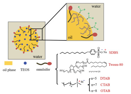
Schematic illustration of the emulsion droplet and the distribution of molecules at the O/W interface.
Study on the morphological regulation mechanism of hollow silica microsphere prepared via emulsion droplet template
Chu Zhao , Zhiqing Ge , Zhuoni Jiang , Shuo Yan , Jingjing Shu , Mozhen Wang , Xuewu Ge

Hollow silica microspheres have broad application prospects in the fields of drug sustained-release, adsorption and separation, catalysis, energy storage, heat insulation and so on because of their advantages of nontoxic, large internal cavity, low density, large surface area and good thermal stability [1-7]. The properties and applications of hollow silica microspheres are closely related to their morphology (including particle size, wall thickness, and pore structure, etc.), which should be regulated according to the preparation method of the hollow microspheres [8-13]. The preparation methods of hollow silica microspheres include sacrificial template method, self-template method and spray drying [14-16]. Sacrificial template method is widely used because it can prepare hollow silica microspheres with controllable morphology by using a variety of specific templates or changing synthesis conditions and parameters. Sacrificial templates are usually divided into two categories, hard templates (solid) and soft templates (liquid or gaseous). Hard templates are generally polymer (such as polystyrene (PS)) or inorganic (such as calcium carbonate, carbon) particles [17-19]. In the previous work of our group [16], hollow silica microspheres with different wall thickness were successfully prepared using the monodisperse PS microspheres with a diameter of 1.4 µm as the hard template. Since the hard template itself will not deform, it is easy to obtain hollow microspheres with expected morphology. However, the preparation of hard templates is usually complex, time-consuming, and energy-consuming, and the removal of templates generally requires calcination or organic solvent, which brings serious environmental problems to its practical application [20-23].
Soft templates for the formation of hollow silica microspheres include surfactant micelles, emulsion droplets, and bubbles [24-26]. The silica precursor molecules diffuse to the soft template interface and react to form a silica shell, then the template is removed by washing or evaporation [11, 27-30]. Emulsion droplets are often used as the soft templates for the synthesis of hollow silica microspheres because of their composition diversity and wide size range (from a few nanometers to several microns) [31, 32]. Ma et al. [33] prepared emulsion droplet soft templates composed of decane and 1,2-bis(triethoxylsilane) ethane (BTSE) to synthesize hollow silica microspheres with a size of 163~560 nm and a shell thickness up to 70 nm by the hydrolysis and condensation of BTSE at the droplet interface catalyzed by ammonia. Teng et al. [34] prepared hollow silica microspheres by using cetyltrimethylammonium bromide (CTAB) stabilized TEOS droplets as the soft templates. It was found that the hollow microspheres could be obtained only at the presence of an appropriate amount of ethanol. Since the emulsion stability is sensitive to the thermodynamic and kinetic parameters of the system, the deformation and aggregation of the emulsion droplets, even de-emulsification are easy to occur when the composition and the temperature of the system change with the reaction process, making it difficult to control the morphology uniformity of the hollow silica microspheres, and producing undesirable by-products with collapse and irregular morphology [35, 36]. Emulsifier is the crucial component for the emulsion stability. Cationic emulsifiers or a mixed type of cationic and non-ionic emulsifiers are generally used to prepare hollow silica microspheres [37-40]. Wu et al. [41] used CTAB as the emulsifier and hexadecane as the co-stabilizer to prepare an O/W microemulsion with the mixture of TEOS and octane as oil phase and finally fabricate hollow silica microspheres with a shell thickness varying in the range of 6~12 nm and a whole microsphere diameter up to 150 nm by adjusting the content of CTAB and TEOS. Although there have been a lot of specific research work on the preparation of hollow silica microspheres via soft template method, detailed discussion on the correlation between the chemical structure and content of each component in the emulsion system and the morphology of hollow silica microspheres is lacking, i.e., the mechanism of the morphology regulation of hollow silica is not clear, which limits the application of soft template method in the synthesis of hollow silica microspheres with precise morphology [42, 43].
In this paper, an O/W emulsion system with the mixed liquid paraffin and TEOS as the oil phase was prepared as soft templates for the synthesis of hollow silica microspheres. Based on the detailed studies on the effects of the emulsifier structure and content, TEOS content, catalyst type, and the components in water and oil phases on the synthesis and the morphology (including particle size, silica wall thickness and structure) of hollow silica microspheres, the morphology regulation mechanism of hollow silica microspheres is discussed in depth.
In an emulsion system, the oil phase disperses in water in the form of droplets with the help of the emulsifier. As shown in Fig. 1, a layer of emulsifier molecules is located at the interface of the droplets. The precursor of silica, TEOS, is hydrophobic, which should be mainly located in the oil phase. Only when it diffuses to the oil-water interface and contacts with water molecules, the hydrolysis and condensation reaction of TEOS can occur, which should be the prerequisite for the formation of silica shell at the interface. Obviously, the charge property and the molecular structure of the emulsifier will affect the diffusion and contact of TEOS and water molecules to the oil-water interface through the electrostatic and spatial interaction. Therefore, three types of emulsifiers with the HLB value of 8~18, i.e., cationic emulsifiers (DTAB, CTAB and OTAB), non-ionic emulsifiers (Tween-80), and anionic emulsifiers (SDBS) are selected in this work to study the influence of emulsifier on the synthesis and morphology of hollow silica microspheres.
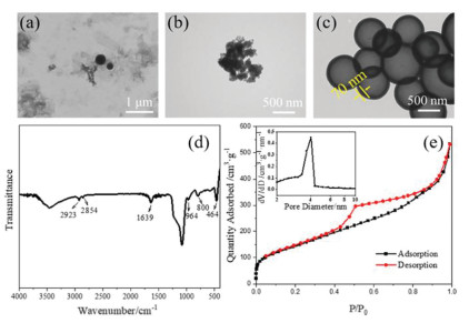
Figs. 2a-c show the TEM images of silica microspheres prepared by different emulsifiers at the same reaction conditions. When non-ionic (Tween-80) or anionic (SDBS) emulsifier was adopted, only a small amount of solid product rather than hollow microspheres was obtained. However, when cationic emulsifier CTAB was used, the products are almost all hollow microspheres with regular morphology (Fig. 2c), which have an average particle diameter of 930 nm and a wall thickness of about 70 nm. The infrared spectrum of the obtained hollow microspheres is shown in Fig. 2d, which is almost the same as those of silica particles synthesized by Stöber method in the literature [16, 44, 45]. The strong and wide absorption band near 1080 cm−1 is assigned to the anti-symmetric stretching vibration of Si-O-Si. The peak at 964 cm−1 is the bending vibration absorption peak of Si-OH. The absorptions at 800 cm−1 and 464 cm−1 correspond to the symmetric stretching and bending vibrations of Si-O-Si respectively. The absorptions at 3430 cm−1 and 1639 cm−1 indicate the existence of the adsorbed water molecules. The weak absorption peaks at 2923 cm−1 and 2854 cm−1 correspond to the asymmetric and symmetric stretching vibration absorption peaks of C—H, indicating that the Si-OR bonds in TEOS have not completely hydrolyzed. The adsorption-desorption isotherms of the hollow silica microspheres are shown in Fig. 2e. According to the BDDT classification, it can be identified as a type IV isotherms with typical H3 hysteresis rings, indicating the presence of mesopores in the silica wall [46, 47]. The BET specific surface area of microspheres is as high as 536.8 m2/g. The BJH pore size distribution is also shown in Fig. 2e, which shows an average pore diameter of 5.5 nm.
The above results indicate that the charge property of the emulsifier is the critical condition for the synthesis of hollow silica microspheres. As shown in Fig. 1, if the hydrophilic end of the emulsifier is positively charged, it will be beneficial to attract water molecules and TEOS to diffuse to the interface through electrostatic interaction since both of them have electron-rich O atoms, thus promoting the hydrolysis of TEOS and further condensation reaction to form silica. When the hydrophilic end of the emulsifier is negatively charged, it will generate electrostatic repulsion to the electron-rich groups in the surrounding molecules, which makes it difficult for water and TEOS molecules to approach and react at the interface. Non-ionic emulsifiers are generally neutral long-chain molecules, which isolate and stabilize the oil and water phases through the spatial barrier effect of the hydrophilic long chain. Consequently, TEOS and water molecules are unable to contact and react with each other at the droplet interface. Therefore, in the emulsion system stabilized by anionic and non-ionic emulsifiers, no hollow microspheres could be formed. Only those TEOS dissolved in water were reacted with water to give a small amount of silica solid product.
Obviously, in addition to the charge property, the hydrophobic chain structure and the content of emulsifier will also affect the diffusion of TEOS molecules to the interface so as to affect the morphology of the formed silica wall. Fig. 3 shows the morphology of silica microspheres prepared by using three kinds of cationic emulsifiers with different lengths of hydrophobic chains at different emulsifier concentrations. DTAB has a shorter hydrophobic chain (12 carbon atoms). At the same concentration, its emulsifying effect is worse than that of CTAB containing an aliphatic chain of 16 carbon atoms and OTAB containing an aliphatic chain of 18 carbon atoms. The emulsion stabilized by DTAB is slightly creaming, leading to the formation of both hollow and solid microspheres, as shown in Figs. 3a1-a3. However, hollow silica microspheres are mainly obtained from the emulsion systems stabilized with CTAB and OTAB, as shown in Figs. 3b1-b3, c1-c3. It is also noted that the longer the hydrophobic chain of the emulsifier, the more complete and thicker the silica wall of the hollow microspheres.
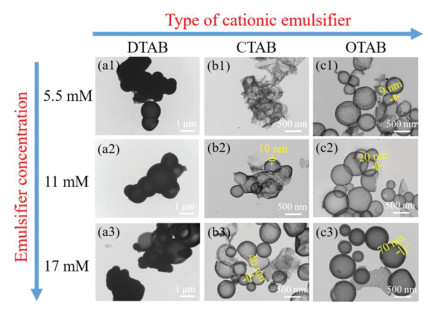
At the same time, Fig. 3 also shows that the concentration of the emulsifier also has influence on the morphology of the obtained hollow microspheres. Obviously, the wall thickness of the hollow silica microspheres increases with the concentration of emulsifier. As for OTAB system, the wall thickness varies from 9 nm to 70 nm with the increase of the OTAB concentration from 5.5 mmol/L to 17 mmol/L. A similar trend appears in the CTAB system, except that the wall thickness of the microspheres from CTAB system is smaller than that from the OTAB system at the same emulsifier concentration.
It should be noted that the emulsifier concentration seems to have little effect on the whole microsphere size which is polydispersed for all investigated systems. For example, for the case of the CTAB concentration of 11 mmol/L, the diameter of hollow microspheres ranges from 0.24 µm to 1.01 µm, while CTAB concentration increases to 17 mmol/L, the range of the diameter of hollow microspheres remains nearly unchanged, i.e., from 0.21 µm to 1.21 µm.
It can be concluded that cationic emulsifier with a hydrophobic chain of appropriate length is a necessary condition for the successful synthesis of hollow silica microspheres. When the hydrophobic chain is long enough, the excellent chain flexibility is beneficial to reduce the diffusion resistance of TEOS molecules from the inside of oil droplet to the O/W interface. On the other hand, a higher concentration of emulsifier makes the droplets more stable. These factors are conducive to promoting the diffusion of TEOS, so the wall thickness of hollow microspheres increases with the hydrophobic chain length and the concentration of the emulsifier.
Figs. 4a1-a3 show the morphologies of the hollow silica microspheres prepared at different TEOS content in the oil droplet. It can be observed that when the amount of TEOS increases from 6 mL to 12 mL (the volume ratio of TEOS/oil increases from 0.55 to 0.71), the average diameter of the obtained hollow silica microspheres increases from 660 nm to 820 nm, and the wall thickness also increases from 40 nm to 100 nm. If the amount of TEOS continues to increase to 18 mL (the volume ratio of TEOS/oil increases to 0.78), the average diameter of hollow microspheres will be increased to 1.04 µm, but the wall thickness remains about 100 nm. The result indicates that the diffusion and contact of TEOS and water molecules will become more and more difficult with the increase of the silica wall thickness. When the wall is thick enough, the reaction of TEOS will be so slow that the silica wall thickness cannot be observed to change anymore.
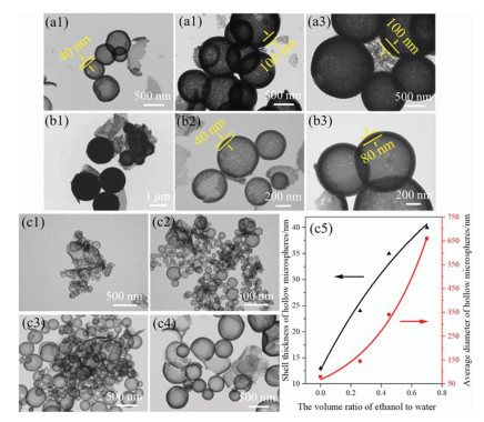
The hydrolysis condensation reaction of TEOS is usually catalyzed by alkali. In an emulsion system, the addition of alkali can not only adjust the pH, but also may affect the stability of the emulsion, thus the morphology of the final product. In this work, when tetraethyl ammonium hydroxide (a quaternary ammonium base, completely ionized in water) was dropped in the emulsion as the catalyst, the system was instantly demulsified because the double-electric layer at the interface of oil droplets was destroyed by the ionized quaternary ammonium base. As a result, the oil droplets disappeared, and some solid silica particles, rather than hollow microspheres, are formed in water phase by self-nucleation, as shown in Fig. 4b1. On the other hand, the organic weak base, such as triethylamine and ammonia, won't affect the stability of the emulsion system, so hollow silica microspheres with similar diameter (~660 nm) were obtained when triethylamine or ammonia was used as the catalyst, as shown in Figs. 4b2 and b3. However, the catalyst activity of triethylamine is higher than that of ammonia. Under the same reaction conditions, the reaction rate of TEOS in the triethylamine catalytic system is faster than that in the ammonia catalytic system, so the wall thickness of the hollow silica microspheres obtained from the former (80 nm) is larger than that from the latter (40 nm).
The stability and droplet size distribution of the emulsion system are closely related to the oil-water interfacial tension and the distribution of emulsifier molecules at the droplet interface, which is determined by the compositions of both oil and water phases. Usually, a certain amount of ethanol is added in water to adjust the hydrolysis reaction rate of TEOS [48, 49], which will lead to the decrease in the oil-water interfacial tension and the increase of the solubility of the emulsifier in the continuous phase. Thus, the influence of ethanol content in water on the morphology of the hollow silica microspheres also has been investigated in this work. Figs. 4c1-c4 show the morphologies of hollow silica microspheres prepared under different volume ratio of alcohol to water in the aqueous continuous phase, i.e., 0, 0.26, 0.45, 0.7 (the corresponding surface tension of continuous phase at room temperature (17.5 ℃) are 73.1, 42, 35.4 and 31.4 mN/m, respectively). The relationships between the average diameter and wall thickness of hollow microspheres and the volume ratio of alcohol to water derived from Figs. 4c1-c4 are shown in Fig. 4c5, which shows that both the average diameter and the wall thickness of hollow silica microspheres increase with the volume ratio of alcohol to water, especially the average diameter, which changes by one order of magnitude from 96 nm to 660 nm. The wall thickness varies relative slightly, from 13 nm to 40 nm. Evidently, with the increase of ethanol content, the rapid decrease of oil-water interfacial tension and the increase of solubility of CTAB in water phase deteriorate the performance of the emulsifier, resulting in the increase of the droplet size and the decrease of the emulsifier stability. At the same time, the reaction rate of TEOS is also slowed down by the increase of the ethanol content, which is insufficient to form a complete silica wall for larger droplets within the same reaction time so that the amount of broken microspheres increases (Fig. 4c4).
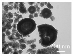
In addition to the silica precursor molecules, the emulsion droplet soft templates usually contain substances that can be easily removed, also known as porogen. In the above work, paraffin is the porogen since it can be dissolved and removed with ethanol. It has been reported in the literature that some organic solvents, such as benzyl alcohol, cyclohexane and tetrahydrofuran, can be used to regulate the morphology of silica [50-52]. For example, cyclohexane is an essential key component for the formation of a fibrous mesoporous silica microsphere [52]. Cyclohexane is hydrophobic and volatile, so we used it instead of paraffin to prepare the droplet soft template for the production of hollow silica microspheres. In order to verify the idea about the influence of the type of oil phase on the morphology of hollow silica microspheres, we use the synthesis condition that can ensure the fibrous silica layer can be formed. As shown in Fig. 5, hollow silica microspheres with a special fibrous silica wall can be obtained when cyclohexane is used as the porogen. The diameter of the hollow microspheres ranges from 116 nm to 600 nm, and the wall thickness is about 85 nm. The result means the silica wall morphology also can be regulated by the component of the soft template.
In this paper, an O/W emulsion system with a mixture of liquid paraffin and TEOS as the oil phase was prepared as soft templates for the fabrication of hollow silica microspheres. The effects of the emulsifier structure and content, TEOS content, catalyst type, and the components in water and oil phases on the synthesis and the morphology (including particle size, silica wall thickness and structure) of the prepared hollow silica microspheres have been studied in detail. The results show that the diffusion of TEOS and water molecules to the oil-water interface and the hydrolysis condensation reaction of TEOS at the oil-water interface are two critical processes for the synthesis and morphological regulation of hollow silica microspheres. Cationic emulsifier with a hydrophobic chain of appropriate length is a necessary condition for the successful synthesis of hollow silica microspheres. The ethanol content in the water phase is the dominant factor to regulate the size of hollow microspheres, which can be changed in a wide range of 96~660 nm with the increase of the volume ratio of alcohol-water from 0 to 0.7. The silica wall thickness can be up to 100 nm with this method, mainly depending on the content of the emulsifier and TEOS, the hydrophobic chain length of the emulsifier, as well as the activity of alkaline catalysts. In addition, the component of oil phase can regulate the pore structure of the silica wall. When the liquid paraffin in emulsion droplets is replaced by cyclohexane, hollow microspheres with fibrous mesoporous silica wall can be fabricated. It is worth mentioning that the paraffin used in the experiment can act not only as the porogen, it is also a common phase change material, which means this work also provides an efficient method to prepare silica coated paraffin phase change materials. Therefore, the research of this work not only enriches the basic theory of interfacial polymerization in the emulsion system, but also provides ideas and methods for expanding the preparation and application of multifunctional silica microsphere material.
The authors declare that they have no known competing financial interests or personal relationships that could have appeared to influence the work reported in this paper.
This work is supported by the National Natural Science Foundation of China (Nos. 51973205, 51773189), Zhuhai IndustryUniversity-Research Institute Collaboration & Basic and Applied Basic Research Project (No. ZH22017001210059PWC), and the Fundamental Research Funds for the Central Universities (Nos. WK9110000066, WK3450000005 and WK3450000006).
Supplementary material associated with this article can be found, in the online version, at doi:
C. Hanske, M.N. Sanz-Ortiz, L.M. Liz-Marzan, Adv. Mater. 30 (2018) 1707003. doi: 10.1002/adma.201707003
J.Y. Wang, J.W. Wan, D. Wang, Acc. Chem. Res. 52 (2019) 2169–2178. doi: 10.1021/acs.accounts.9b00112
Y. Boyjoo, M.W. Wang, V.K. Pareek, J. Liu, M. Jaroniec, Chem. Soc. Rev. 45 (2016) 6013–6047. doi: 10.1039/C6CS00060F
H. Chen, Z.J. Yan, B.Z. Li, Y. Li, Q.H. Wu, Mater. Lett. 112 (2013) 78–80. doi: 10.1016/j.matlet.2013.09.040
Y. Bao, C.H. Shi, T. Wang, X.L. Li, J.Z. Ma, Microporous Mesoporous Mater 227 (2016) 121–136. doi: 10.1016/j.micromeso.2016.02.040
T.L. Zhang, Z.G. Lu, L.Y. Zhang, et al., Chin. Chem. Lett. 31 (2020) 3135–3138. doi: 10.1016/j.cclet.2020.07.010
X.Z. Zhou, X.Y. Yan, L. Zhu, et al., Chinese J. Chem. Phys. 33 (2020) 749–756. doi: 10.1063/1674-0068/cjcp1909161
J. Chen, X. Wu, X.D. Hou, et al., ACS Appl. Mater. Interfaces 6 (2014) 21921–21930. doi: 10.1021/am507642t
A. Belostozky, S. Bretler, M. Kolitz-Domb, I. Grinberg, S. Margel, Mater. Sci. Eng. C 97 (2019) 760–767. doi: 10.1016/j.msec.2018.12.093
S.S. Park, C.S. Ha, Adv. Funct. Mater. 28 (2018) 1703814. doi: 10.1002/adfm.201703814
Y. Gao, S.J. Ding, X.Y. Huang, et al., Drug Dev. Ind. Pharm. 45 (2019) 273–281. doi: 10.1080/03639045.2018.1539098
S.D. Jiang, G. Tang, Z.M. Bai, Y. Pan, Mater. Lett. 247 (2019) 139–142. doi: 10.1016/j.matlet.2019.03.113
W.X. Yang, G.Q. Xu, J.J. Shu, M.Z. Wang, X.W. Ge, Chin. Chem. Lett. 32 (2021) 866–869. doi: 10.3390/agriculture11090866
M. Gao, J. Zeng, K. Liang, D.Y. Zhao, B. Kong, Adv. Funct. Mater. 30 (2020) 1906950. doi: 10.1002/adfm.201906950
C.Y. Tao, X.S. Zou, K. Du, et al., Opt. Lett. 43 (2018) 1802–1805. doi: 10.1364/ol.43.001802
J.J. Shu, J. Chen, Y.W. Chen, et al., J. Univ. Sci. Technol. Chin. 51 (2021) 494–504.
M. Jiang, J.J. Shu, H.Q. Jin, et al., J. Radiat. Res. Radiat. Process. 37 (2019) 050203.
G.Y. Fang, Z. Chen, H. Li, Chem. Eng. J. 163 (2010) 154–159. doi: 10.1016/j.cej.2010.07.054
Q.H. Zhao, W.B. Yang, Y.S. Li, et al., Int. J. Hydrog. Energy 44 (2020) 4464–4474. doi: 10.1002/er.5224
Y. Nakashima, C. Takai, H. Razavi-Khosroshahi, W. Suthabanditpong, M. Fuji, Adv. Powder Technol. 29 (2018) 904–908. doi: 10.1016/j.apt.2018.01.006
Y. Chen, Y.Y. Wang, J. Inorg. Organomet. Polym. Mater. 27 (2016) 380–384.
S.B. Huang, X.J. Yu, Y.M. Dong, L. Li, X.H. Guo, Colloids Surf. A Physicochem. Eng. Asp. 415 (2012) 22–30. doi: 10.1016/j.colsurfa.2012.09.004
G.W. Duan, L.Z. Xie, C. Zhao, M.Z. Wang, X.W. Ge, Acta Polym. Sin. 5 (2017) 785–792.
C. Vancaeyzeele, F. Olivier, G. Petroffe, S. Peralta, F. Vida, ACS Appl. Mater. Interfaces 9 (2017) 12706–12718. doi: 10.1021/acsami.7b00028
Q.Y. Yu, J.F. Hui, P.P. Wang, X. Wang, Inorg. Chem. 51 (2012) 9539–9543. doi: 10.1021/ic301371q
X.L. Fang, C. Chen, Z.H. Liu, P.X. Liu, N.F. Zheng, Nanoscale 3 (2011) 1632–1639. doi: 10.1039/c0nr00893a
L.H. Zhang, N. Zhan, Q. Jin, H.L. Liu, J. Hu, Ind. Eng. Chem. Res. 55 (2016) 5885–5891. doi: 10.1021/acs.iecr.5b04760
X.D. Sun, Q.R. Wu, W. Li, et al., Chin. Chem. Lett. 33 (2022) 2697–2700. doi: 10.1016/j.cclet.2021.08.122
J. Sharma, G. Polizos, Nanomaterials 10 (2020) 1599. doi: 10.3390/nano10081599
L.J. Xu, T. Yang, J. Wang, F.H. Huang, M.M. Zheng, J. Agric. Food Chem. 69 (2021) 9067–9075. doi: 10.1021/acs.jafc.0c07501
Y.Y. Xie, J. Wang, M.Z. Wang, X.W. Ge, J. Hazard. Mater. 297 (2015) 66–73. doi: 10.1016/j.jhazmat.2015.04.069
M. Jafelicci Jr., M.R. Davolos, F.J. dos Santos, S.J. de Andrade, J. Non. Cryst. Solids 247 (1999) 98–102. doi: 10.1016/S0022-3093(99)00040-X
X.B. Ma, J.J. Zhang, M. Dang, et al., J. Colloid Interface Sci. 475 (2016) 66–71. doi: 10.1016/j.jcis.2016.04.026
Z.G. Teng, Y.D. Han, J. Li, F. Yan, W.S. Yang, Microporous Mesoporous Mater 127 (2010) 67–72. doi: 10.1016/j.micromeso.2009.06.028
M. Artiga-Artigas, J. Montoliu-Boneu, L. Salvia-Trujillo, O. Martin-Belloso, Colloids Surf. A: Physicochem. Eng. Asp. 578 (2019) 123577. doi: 10.1016/j.colsurfa.2019.123577
T. Sheth, S. Seshadri, T. Prileszky, M.E. Helgeson, Nat. Rev. Mater. 5 (2020) 214–228. doi: 10.1038/s41578-019-0161-9
X. Wang, X.R. Miao, Z.M. Li, W.L. Deng, Appl. Surf. Sci. 257 (2011) 2481–2488. doi: 10.1016/j.apsusc.2010.10.005
H. Yan, C. Kim, Colloids Surf. A Physicochem. Eng. Asp. 443 (2014) 88–95. doi: 10.1016/j.colsurfa.2013.10.049
J.J. Chen, H.J. Li, X.H. Zhou, et al., Ceram. Int. 43 (2017) 13907–13912. doi: 10.1016/j.ceramint.2017.07.118
Y.H. Li, N. Li, W. Pan, et al., ACS Appl. Mater. Interfaces 9 (2017) 2123–2129. doi: 10.1021/acsami.6b13876
B. Peng, M. Chen, S.X. Zhou, L.M. Wu, X.H. Ma, J. Colloid Interface Sci. 321 (2008) 67–73. doi: 10.1016/j.jcis.2007.12.044
Y. Nakashima, C. Takai, W.H. Chen, et al., Colloids Surf. A Physicochem. Eng. Asp. 507 (2016) 164–169. doi: 10.1016/j.colsurfa.2016.07.091
Y. Nakashima, C. Takai, H. Razavi-Khosroshahi, M. Fuji, Colloids Surf. A: Physicochem. Eng. Asp. 546 (2018) 301–306. doi: 10.1016/j.colsurfa.2018.03.033
N. Ezzati, A.R. Mahjoub, A.A. Shahrnoy, Z. Syrgiannis, Int. J. Pharm. 572 (2019) 118709. doi: 10.1016/j.ijpharm.2019.118709
Z.G. Teng, S.J. Wang, X.D. Su, et al., Adv. Mater. 26 (2014) 3741–3747. doi: 10.1002/adma.201400136
M. O'Sullivan, Z.B. Zhang, B. Vincent, Langmuir 25 (2009) 7962–7966. doi: 10.1021/la9006229
S. Brunauer, L.S. Deming, W.E. Deming, E. Teller, J. Am. Chem. Soc. 62 (2002) 1723–1732.
J. Musgo, J.C. Echeverría, J. Estella, M. Laguna, J.J. Garrido, Microporous Mesoporous Mater 118 (2009) 280–287. doi: 10.1016/j.micromeso.2008.08.044
Q. Chen, Y.L. Ge, H. Granbohm, S.P. Hannula, Nanomaterials 8 (2018) 362. doi: 10.3390/nano8060362
X. Wang, X.R. Miao, Z.M. Li, W.L. Deng, J. Non. Cryst. Solids 356 (2010) 898–905. doi: 10.1016/j.jnoncrysol.2009.12.029
Y.L. Chen, Y. Li, Y.X. Chen, et al., Chem. Commun. 34 (2009) 5177–5179. doi: 10.1039/b903859k
J. Bahadur, A. Maity, D. Sen, A. Das, V. Polshettiwar, Langmuir 37 (2021) 6423–6434. doi: 10.1021/acs.langmuir.1c00368

Figure 1 Schematic illustration of the emulsion droplet and the distribution of molecules at the O/W interface.

Figure 2 TEM images of silica microspheres prepared with different type of emulsifiers: (a) Tween-80 (sample T-1), (b) SDBS (sample S-1) and (c) CTAB (sample C-4). (d, e) The IR spectrum and nitrogen adsorption-desorption isotherms of the hollow microspheres in (c) respectively. The inset in (e) is the BJH pore size distribution calculated from the desorption isotherm.

Figure 3 TEM images of silica microspheres prepared with different cationic emulsifiers at certain concentrations: (a1-a3) DTAB (sample D-1, D-2, D-3); (b1-b3) CTAB (sample C-1, C-2, C-3); (c1-c3) OTAB (sample O-1, O-2, O-3).

Figure 4 TEM images of hollow silica microspheres prepared with different amount of TEOS: (a1) 6 mL (sample C-3), (a2) 12 mL (sample C-7), (a3) 18 mL (sample C-8). TEM images of silica microspheres prepared with different catalysts: (b1) TEAH/H2O (sample C-5), (b2) NH3·H2O (sample C-3), (b3) TEA (sample C-6). TEM images of the hollow silica microspheres prepared with different volume ratio of ethanol to water: (c1) 0 (sample C-11), (c2) 0.26 (sample C-10), (c3) 0.45 (sample C-9), (c4) 0.7 (sample C-3), and (c5) the dependence of the average diameter and silica wall thickness on the volume ratio of ethanol to water derived from (c1) to (c4).

 扫一扫看文章

扫一扫关注我们
 DownLoad:
 下载:
下载:
