Received Date:
03 March 2022 Accepted Date:
18 April 2022 Revised Date:
14 April 2022 Available Online:
15 April 2023
Abstract:
Air-breathing proton exchange membrane fuel cells (PEMFCs) are very promising portable energy with many advantages. However, its power density is low and many additional supporting parts affect its specific power. In this paper, we aim to improve the air diffusion and fuel cell performance by employing a novel condensing-tower-like curved flow field rather than an additional fan, making the fuel cell more compact and has less internal power consumption. Polarization curve test and galvanostatic discharge test are carried out and proved that curved flow field can strengthen the air diffusion into the PEMFC and improve its performance. With appropriate curved flow field, the fuel cell peak power can be 55.2% higher than that of planar flow field in our study. A four-layer stack with curved cathode flow field is fabricated and has a peak power of 2.35 W (120 W/kg).
With the development of portable electronic devices such as notebook computers and electronic cameras, demand for portable power supply with light weight and high energy density is becoming higher and higher [1-3]. As an energy conversion device with high energy density [4, 5], high energy conversion efficiency [6-8], fast restarting speed [9, 10] and environmental friendliness [11, 12], proton exchange membrane fuel cell (PEMFC) is a promising portable energy supply and has attracted great attention. Compare to the most common lithium battery in the portable energy market, traditional PEMFC system has complex auxiliary devices for fuel and oxidant supply, temperature control and humidification. These auxiliary devices not only consume the energy of the fuel cell, increase the mass, volume and cost, but also are hard to miniaturize [13-15].
To simplify the PEMFC system, air-breathing PEMFC was developed. The air-breathing PEMFC has eliminated most of those auxiliary devices and is more compact and suitable for portable use. However, it also has some problems, including high weight, low operating temperature, low humidity and low mass transfer ability, etc. Its bipolar plates are mostly made of graphite or metal which are heavy and hard to process and usually account for more than 80% of the total mass and volume, 40% of the cost of PEMFC stacks [16-18]. These seriously affect the specific power of the stack. On the other hand, due to the low operating temperature, pressure, humidity and the free diffusion way of air supplying on the cathode side, its specific power is far lower than that of traditional fuel cell [19, 20]. These problems hinder the application of air-breathing fuel cells in portable energy.
In order to improve the performance of air-breathing PEMFC, a lot of efforts have been made to solve the above problems. First, as for heavy bipolar plates, a new structure has been developed. The current of fuel cell is collected along the gas diffusion layer, but not through the bipolar plate. The current collecting function of the bipolar plate is replaced by the highly conductive perforated gas diffusion layer. Consequently, the bipolar plate can be made by non-conductive plastic materials which are light, flexible, widely available, and easy to make. Through the innovation of the new structure, the mass and volume of the bipolar plates could be significantly reduced and thus the fuel cell specific mass and volume power density could be greatly improved [5, 21].
Second, it is highly challenging to improve the performance of air-breathing PEMFC under the natural conditions, including low temperature, low humidity and slow mass transfer. Usually, these conditions are strongly correlated. In order to know the details, mathematic simulations have been carried out on the cathode side of air-breathing PEMFC. It was found out that the natural convection boundary layer is a primary limitation to the performance of air-breathing PEMFC and the performance could be improved by magnifying natural convection [22]. Also, by using low thermal conductivity materials in fuel cell fabrication to keep high fuel cell temperature, the saturation pressure and buoyancy induced flow on fuel cell cathode side could be increased, which will lead to better water removal and fuel cell performance [23]. These works revealed that the key to improve the performance of air-breathing PEMFC is to improve the passive air convection on its cathode side.
In order to control these conditions, many researchers have carried out studies on the cathode flow field of air-breathing PEMFC to improve the air convection. Their studies can mainly be divided into two types, the open and channeled-cathode type. The open-cathode type is more suitable for low power devices because it has the biggest open area for passive air diffusion and water removal [24]. Moreover, the cathode flow field opening shape and opening ratio have significant effects on oxygen transportation and water removal of air-breathing PEMFC [25]. Some novel structures have been applied to the open-cathode side of air-breathing PEMFC, such as fin structure [26], parallel slit, circular opening and oblique slit structure [27]. These structures could enhance the air diffusion and water removal of the fuel cell cathode side, so as to improve the fuel cell performance. As for the channeled-cathode type, the cathode flow field channel design and parameters are crucial to achieving high performance [28]. A certain bending of the flow field channel [28] or a wave feature at flow field bottom [29] could strengthen the air diffusion into the GDL and improve the fuel cell performance. These researches have proved that diverse modifications can be made to the cathode flow field to improve the fuel cell performance. However, both the two types of flow field have their own problems. The open area of open-cathode type is too large for portable stack, and an additional fan is needed for the channeled-cathode type as the passive air convection in it is poor. A new channel-cathode type with good passive air convection is an urgent need for air-breathing PEMFCs.
The condensing tower is an essential part of the thermal power station for the cooling of the plant unit. It can effectively bring the heat and water upwards to the upper air by natural convection. Some studies have been conducted to compare the effects of different tower configurations to their thermal and flow performance [30, 31]. The results indicate that the hyperbolic structure has the highest pressure difference among all the common designs of the condensing tower in windless condition. It is promising to apply the hyperbolic condensing tower structure to the cathode flow field channel of air-breathing PEMFC to improve the passive air convection and water removal of the fuel cell cathode side.
In this study, we focus on improving the performance of air-breathing PEMFC by utilizing light material and optimizing the structure on its channeled-cathode flow field rather than an additional fan. Inspired by the hyperbolic condensing tower of thermal power station, a condensing-tower-like curved cathode flow field is designed and prepared by 3D printing methods. The effects of different curved arc, height and fuel cell orientation on the performance of the fuel cell are systematically studied in this research. With appropriate curved flow field, the peak power of the fuel cell can be significantly increased (maximum 55.2% in our study). Furthermore, a four-layer stack with this curved cathode flow field is fabricated and has a maximum output power of 2.35 W.
Preparation of membrane electrode assembly (MEA): The MEA with highly conductive gas diffusion layer used in this study was prepared as follows. First a perforated graphene sheet was attached to a commercial carbon paper (SGL 29BC with microporous layer) with 500 µL/cm2 carbon powder ink (10 mg Vulcan XC-72R active carbon mixed and dispersed with 50 µL 6% PTFE dispersion in 10 mL ethanol), then it was treated in a muffle furnace (350 ℃ for 30 min) to form the highly conductive gas diffusion layer. After that the catalyst ink (0.5 mg/cm2, 20 mg 70% Pt/C mixed and dispersed with 0.1 g 5% Nafion in 0.5 g 1:1 IPA/H2O mixed solvent) was scraped onto the diffusion layer and kept in an oven (105 ℃ for 2 h) to remove the solvent. Finally, the catalyst coated diffusion layer was combined with Nafion XL membrane by hot press (500 psi for 2 min). The size of the MEA is 1.5 × 5 cm2 with an effective area of 1 × 5 cm2 in our research. The area without catalyst coating is used for conducting the current out and with silver strips (thickness 100 µm) attached.
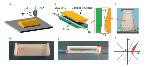
Preparation of the single cell with curved flow fields: The preparation of single cell with curved cathode flow field is as shown in Fig. 1. The anode and cathode flow field plates are first designed on computer, then prepared by 3D printing (with nozzle temperature 210 ℃ and plane temperature 90 ℃) with polylactic acid (PLA, Lanbo printing consumables Co., Ltd.) as the printing substrate (Fig. 1a). The anode flow field is single serpentine type (ridge width 1 mm, channel width 4.7 mm and height 1 mm) and is combined with the MEA by silicone sealant. Two silver strips are attached to the two sides of the MEA with conductive adhesive (a mixture of silver powder/epoxy adhesive with a mass ratio of 4:1) to conduct the current [5, 32]. Finally, the cathode flow field plate is fixed onto it to form a curved cathode flow channel (Fig. 1b) similar to a condensing tower (Fig. 1c). Figs. 1d and e are the pictures of curved flow field plate and single cell with curved cathode flow field. The curved cathode flow field is constructed by a hyperbola curve as shown in Fig. 1f [33, 34].
Figure 1
Figure 1.
Schematic illustration of the air-breathing PEMFC fabrication with condensing-tower-like cathode flow field. (a) Preparation of the condensing-tower-like cathode flow field by 3D printing. (b) Illustration of the single cell with curved cathode flow field. (c) Picture of a condensing tower. (d) Picture of curved cathode flow field. (e) Picture of the single cell with curved cathode flow field. (f) Building method of the curved surfaces.
The stack consists of four MEAs with a size of 1.5 × 5 cm2. They are first combined with a bipolar plate which is a combination of the anode and curved cathode plate, then piled up with the hydrogen path being connected and sealed by silicone sealant. Silver strips were used to conducted the current and connect the four fuel cells. Two end plates are used to fix the stack. The details are shown in Fig. S7 (Supporting information).
The electrochemical performance was tested (including polarization curve test and galvanostatic discharge test) by a fuel cell tester (BST-10V20A-8CH, BettaTeQ Co., Ltd.) with four-electrode method. All the tests were carried out by air-breathing mode under room temperature and humidity. The temperature was tested by a thermocouple with a multimeter. The hydrogen was supplied by a hydrogen generator (JM-300, Junming Analytical Instrument Co., Ltd.) and the flux was 60 mL/min, no fan was used for forced air convention in this study. The polarization test was tested in step discharge mode. The single cell discharges at a series of current stages (step length 0.2 A) and is kept for 2 min at each stage. The balanced discharge voltages of the current stages are recorded and drawn into polarization curves. The experimental setup of the test is shown in Fig. S1 (Supporting information).
The design of the condensing-tower-like cathode flow field for air-breathing PEMFC is based on two effects. In hyperbolic curved flow field, it could generate stack effect (Fig. 1b). The hot air heated by the fuel cell goes up and the cold air goes in from the bottom, thus forming natural convection in the cathode flow field. Furthermore, according to Bernoulli Equation, the flow rate of air convection will increase as flow field narrows and reaches maximum at the vertex of the curved surface. With the superposition of the two effects, the natural convection in cathode flow field is greatly strengthened. It is promising to improve the performance of air-breathing PEMFC by using the condensing-tower-like cathode flow field with the two effects.
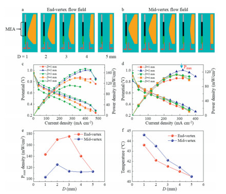
First, the influence of vertex locations of the curved cathode flow fields on fuel cell performance is studied. As shown in Figs. 2a and b, two kinds of curved flow fields with different hyperbolic vertex locations are prepared. One has the vertex of the curved surface at one end (end-vertex in Fig. 2a) and the other has the vertex in the middle (mid-vertex in Fig. 2b) of the MEA. Furthermore, the distance between the vertex and MEA (D) is also systematically varied from 1 mm to 5 mm for the two kinds of curved flow fields.
Figure 2
Figure 2.
Characterization of different curved surface vertex position and vertex-MEA distances (D) on fuel cell performance. (a) Illustration of curved flow field with vertex at one end of the MEA (end-vertex flow field) and its variation with D. (b) Illustration of curved flow field with vertex at middle of the MEA (mid-vertex flow field) and its variation with D. (c) Polarization curves and the power density variations of (a). (d) Polarization curves and the power density variations of (b.) (e) The peak power changes of (c) and (d). (f) The temperature variation with D inside the two kinds of flow fields at a discharge current of 1 A.
Fig. 2c is the polarization curves and the power density variations of the fuel cell with end-vertex flow field as D changes. With the increase of D, the fuel cell performance first increases and then decreases. Hence, there is an optimum value at D = 3 mm for the PEMFC with end-vertex flow field. Similarly, with the increase of D, the fuel cell performance first increases and then decreases for the PEMFC with mid-vertex flow field (Fig. 2d). But its optimum distance value appears at D = 2 mm.
In order to further understand the effect of the hyperbolic parameters on the performance of fuel cell, Fig. 2e clearly shows the variation of peak power density with D for both end-vertex and mid-vertex flow fields. The maximum appears at D = 3 mm with end-vertex flow field and D = 2 mm with mid-vertex flow field. The appearance of maximum peak power density indicates that the two condensing-tower-like structures have a promotion effect on the performance of fuel cell. As D is lower than the optimum value, the vertex of the curved surface gets closer to the MEA, thus the temperature in the flow field gets higher (Fig. 2f) and enhances the stack effect. However, if the neck of the air channel is too narrow (D = 1 mm), though the temperature is the highest, the air flow is severely blocked and therefore the fuel cell performance is reduced. As D is higher than the optimum value, the vertex of the curved surface gets farther to the MEA, thus the temperature in the flow field gets lower (Fig. 2f). Although the air feed is enough when the neck of the air channel is wide (D = 5 mm), the fuel cell performance is also reduced. Therefore, this improvement in fuel cell performance comes from not only more adequate air supply and but also the higher operating temperature. The condensing-tower-like structure has a promotion effect on the natural convection and a better heat-preserving effect.
Comparing the two peak power variation curves in Fig. 2e, the one with end-vertex flow field is better than the other. The vertex of end-vertex flow field is at the lower end of the MEA and the MEA heats above, causing a large temperature difference between the two sides of the vertex. Thus, the stack effect together with the promoting effect of curved surface causes strong natural convection around the neck. Therefore, though the temperature inside mid-vertex flow field is higher (Fig. 2f), the temperature difference between the two sides of the vertex is small and the fuel cell performance is not as good as that of end-vertex flow field.
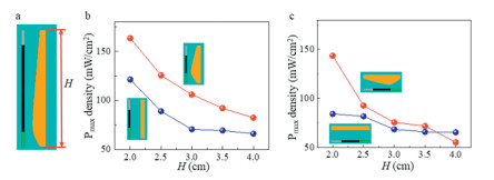
Second, we studied the effects of flow field length on fuel cell performance, since the length is also a key parameter that would affect air convection just like condensing tower. As shown in Fig. 3a, the flow field height (H) varies from 2 cm to 4 cm (MEA height varies from 1.5 cm to 3.5 cm with the same step length). Here, we chose the best curved flow field (vertex at lower end of the MEA, D = 3 mm) and planar flow field as contrast. Fig. 3b shows the variation of peak power density with H under curved and planar flow field in vertical orientation. With the increase of H, the peak power density of both flow fields gradually decreases, which is mainly caused by the current collection method of our experiment. The current is led out as shown in Fig. 1b with two silver strips at one end of our MEA. As the MEA height grows, the distance between the silver strip and the other end of the MEA becomes farther and the resistance between them increases. The increasing resistance results in lower current density, which leads to the reduction of the peak power density as H grows. Furthermore, with the increase of H, the flow field curve flattens and gets more similar planar flow field. Thus, though the peak power density of curved flow field is always higher than that of the planar flow field in Fig. 3b, the gap between them becomes smaller.
Figure 3
Figure 3.
Influence of flow field height on fuel cell performance. (a) Illustration of flow fields with different heights. (b) The variation of peak power with H under planar and curved flow field with D = 3 mm in vertical orientation. (c) The variation of peak power with H under planar and curved flow field with D = 3 mm in horizontal orientation.
Fig. 3c shows the peak power density variation with H under curved and planar flow field in horizontal orientation. With the increase of H, the fuel cell peak power under curved flow field decreases fast while that under planar flow field stays low. Comparing with the variation curve in Fig. 3c, the variation pattern is the same but the variation speed is faster. The fuel cell performance is better in vertical orientation. In brief, in order to fully utilize the improvement effect of curved surface on fuel cell performance and to ensure that the fuel cell device has high power density, the length of curved surface flow field should not be too long and better in vertical orientation. In this research, H = 2 cm is the best.
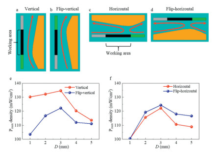
For air-breathing PEMFC without forced convection, the fuel cell orientation will significantly affect the air convection and diffusion on the cathode side [35-37]. Therefore, we selected four orientations, vertical, flip-vertical, horizontal and flip-horizontal (Figs. 4a–d), to study the effect of different fuel cell orientations on fuel cell performance (Figs. 4e and f, H = 2 cm).
Figure 4
Figure 4.
Influence of different orientations on fuel cell performance. (a) Vertical. (b) Flip-vertical. (c) Horizontal. (d) Flip-horizontal. (e) The peak power variation with D in the two orientations of (a) and (b). (f) The peak power variation with D in the two orientations of (c) and (d). The red curves with arrow in (a-d) indicate air convection direction.
Fig. 4e shows that the peak power density first increases then decreases with D under all vertical and flip-vertical orientations, and the peak value is obtained when D = 3 mm. Furthermore, the peak power of vertical orientation is better than that of flip-vertical orientation. It can be explained by comparing the air convection directions in each orientation. In vertical orientation (Fig. 4a), the area with high air velocity is focused at the lower end of the MEA, and the air can fully diffuse into the GDL. Also, the heated air can quickly rise up due to the expanding structure. However, in flip-vertical orientation (Fig. 4b), the area with high air velocity is at the upper end of the MEA, playing a weak role in strengthening air diffusion as well as blocking the air from rising up.
Similarly, Fig. 4e shows that the peak power density first increases then decreases with D under all horizontal and flip-horizontal orientations, and the peak value is obtained when D = 3 mm. Furthermore, the peak power of flip-horizontal orientation is better than that of horizontal orientation. In horizontal orientation (Fig. 4c), the component of the air diffusion direction is outward along the MEA normal direction. While in the flip-horizontal orientation (Fig. 4d), it is inward and can strengthen the air diffusion into the GDL. These differences in air diffusion are the reasons for the variations in fuel cell performance under different orientations in Figs. 4b and d [22].
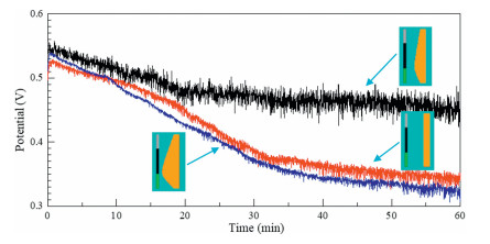
In practical use, it is essential that the fuel cell discharges stably at a relatively high output power. Thus, to characterize the effects of curved flow field on the continuous discharge performance of fuel cell, three different cathode flow fields, i.e., end-vertex flow fields with D = 1, 3, 5 mm, were test through the galvanostatic discharge (Fig. 5). These three end-vertex flow fields are the typical ones in Fig. 2a. The end-vertex flow field with D = 1 mm is a narrow flow field, the end-vertex flow field with D = 3 mm is the optimal one, and the end-vertex flow field with D = 5 mm is the traditional one.
Figure 5
Figure 5.
The galvanostatic discharge test of the fuel cell under different flow fields (end-vertex flow field, D = 1, 3, 5 mm, H = 2 cm) in vertical orientation. The discharge time is 1 h and the current is fixed at 1 A.
Fig. 5 shows that the discharge voltage under these flow fields decreases quickly first and then relatively stabilizes. For the end-vertex flow fields with D = 1 and 5 mm, the voltage decreases quickly from about 0.53 V to about 0.36 V in about 32 min, and then decreases slowly from about 0.36 V to about 0.33 V in about 28 min. Differently, for the end-vertex flow field with D = 3 mm, the voltage decreases quickly from about 0.55 V to about 0.48 V in about 20 min, and then decreases slowly from about 0.48 V to about 0.45 V in about 40 min. Hence, the end-vertex flow field with D = 3 mm has much higher stability than those with D = 1 and 5 mm. Moreover, the regulated voltage is higher (~+0.1 V) than that of the other two flow fields. It further shows that the condensing-tower-like structure can strengthen the natural convection and provide more sufficient air supply for high power discharge. With optimized condensing-tower-like curved flow fields, air-breathing PEMFCs can provide high and stable power output for continuous use.
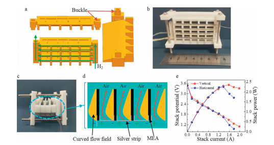
Due to the low open circuit voltage of single fuel cell, PEMFC usually appears in the form of stack in practical application [38, 39]. Therefore, as shown in Figs. 6a and b, we applied the condensing-tower-like curved flow field to fuel cell stack. It is a four-layer air-breathing stack composed of four 1 × 5 cm2 single fuel cells in series. The cathode side of each fuel cell in this stack adopts the most optimized condensing-tower-like curved flow field (vertex at one end of the MEA, D = 3 mm, H = 2 cm) and the fuel cells are connected in series with 100 µm thick silver strips. Figs. 6c and d are the side view of the stack and the illustration of the curved flow field in it.
Figure 6
Figure 6.
Demonstration of PEMFC stack with curved cathode flow field. (a) Illustration of the structure of the four-layer stack with curved cathode flow field (D = 3 mm). (b) Picture of fabricated fuel cell stack. (c) Picture of the condensing-tower-like structure in the stack. (d) Enlarged Illustration of the condensing-tower-like structure in the stack. (e) The polarization curves and the power density variation of the stack in vertical and horizontal direction.
The performance characterization of the stack is shown in Fig. 6e. The polarization curves were tested in horizontal and vertical orientation, respectively. The peak power of the stack is about 2.35 W in both orientations and the difference between those two orientations is small, indicating that the stack has a good orientation stability. The specific mass power density of the stack is 120 W/kg, which is relatively high among the portable PEMFC stacks (45 W/kg in [40] and 18.54 W/kg in [41]) and equivalent to commercial lithium-ion batteries (approximately 80–100 W/kg [40]). This shows that after some optimization, the stack with curved cathode flow field can be used to power digital camera, children's toys and other portable electronic equipment and has good application prospects
In this study, we successfully designed and prepared a new kind of cathode flow field with curved surface. Using 3D printing technology, we can prepare the condensing-tower-like flow field in a simple and fast way. We focus on improving the natural air convection on the cathode side of air-breathing PEMFC through the modification of flow field (applying a condensing-tower-like channel), so as to make it obtain better performance under the most simplified conditions. The experimental results show that the new condensing-tower-like curved flow field can effectively improve the air diffusion into the GDL on the cathode side of air-breathing PEMFC. Under the optimal curved surface, the peak power of the fuel cell is 55.2% higher than that of conventional planar structure. Moreover, we applied the optimal condensing-tower-like curved flow field to the preparation of the stack, and successfully prepared a four-layer stack with orientation stability. Its peak power is about 2.35 W and specific mass power density is 120 W/kg, indicating its application potential in small electronic equipment. The purpose of this study is to improve the performance and stability as well as reducing the additional auxiliary parts of air-breathing PEMFC, thus providing some reference for the preparation of light and high specific power air-breathing stack.
Declaration of competing interest
The authors declare no conflict of interest.
Acknowledgments
The authors are grateful for financial support granted by National Key R&D Program of China from Ministry of Science and Technology of China (Nos. 2020YFB1505700, 2016YFA0200700), China Postdoctoral Science Foundation (No. 2021M702408), the National Natural Science Foundation of China (No. 22172191), Dongyue Polymer Material Company of Dongyue Federation, State Key Laboratory of Fluorinated Functional Membrane Materials (Dongyue Group institute) and Dongyue Future Hydrogen Energy Materials Company. This work was sponsored by the Collaborative Innovation Center of Suzhou Nano Science and Technology. The authors are also grateful for the experiment help from Prof. Yanbin Shen, Mr. Guoyong Xue, Miss Jiajia Xia and Prof. Jiangtao Di.
Supplementary materials
Supplementary material associated with this article can be found, in the online version, at doi:10.1016/j.cclet.2022.04.039.
Figure 1
Schematic illustration of the air-breathing PEMFC fabrication with condensing-tower-like cathode flow field. (a) Preparation of the condensing-tower-like cathode flow field by 3D printing. (b) Illustration of the single cell with curved cathode flow field. (c) Picture of a condensing tower. (d) Picture of curved cathode flow field. (e) Picture of the single cell with curved cathode flow field. (f) Building method of the curved surfaces.
Figure 2
Characterization of different curved surface vertex position and vertex-MEA distances (D) on fuel cell performance. (a) Illustration of curved flow field with vertex at one end of the MEA (end-vertex flow field) and its variation with D. (b) Illustration of curved flow field with vertex at middle of the MEA (mid-vertex flow field) and its variation with D. (c) Polarization curves and the power density variations of (a). (d) Polarization curves and the power density variations of (b.) (e) The peak power changes of (c) and (d). (f) The temperature variation with D inside the two kinds of flow fields at a discharge current of 1 A.
Figure 3
Influence of flow field height on fuel cell performance. (a) Illustration of flow fields with different heights. (b) The variation of peak power with H under planar and curved flow field with D = 3 mm in vertical orientation. (c) The variation of peak power with H under planar and curved flow field with D = 3 mm in horizontal orientation.
Figure 4
Influence of different orientations on fuel cell performance. (a) Vertical. (b) Flip-vertical. (c) Horizontal. (d) Flip-horizontal. (e) The peak power variation with D in the two orientations of (a) and (b). (f) The peak power variation with D in the two orientations of (c) and (d). The red curves with arrow in (a-d) indicate air convection direction.
Figure 5
The galvanostatic discharge test of the fuel cell under different flow fields (end-vertex flow field, D = 1, 3, 5 mm, H = 2 cm) in vertical orientation. The discharge time is 1 h and the current is fixed at 1 A.
Figure 6
Demonstration of PEMFC stack with curved cathode flow field. (a) Illustration of the structure of the four-layer stack with curved cathode flow field (D = 3 mm). (b) Picture of fabricated fuel cell stack. (c) Picture of the condensing-tower-like structure in the stack. (d) Enlarged Illustration of the condensing-tower-like structure in the stack. (e) The polarization curves and the power density variation of the stack in vertical and horizontal direction.

 DownLoad:

 下载:
下载:


