School of Chemical and Environmental Engineering, Yancheng Teachers University, Yancheng 224007, China
b.
MIIT Key Laboratory of Critical Materials Technology for New Energy Conversion and Storage, State Key Laboratory of Urban Water Resource and Environment, School of Chemistry and Chemical Engineering, Harbin Institute of Technology, Harbin 150001, China
c.
Department of Materials Science and Engineering, National University of Singapore, Singapore 117575, Singapore
d.
Institute of Materials Research and Engineering, Agency for Science, Technology and Research (ASTAR), Singapore 138634, Singapore
Received Date:
10 October 2023 Accepted Date:
27 November 2023 Revised Date:
06 November 2023 Available Online:
15 November 2024
Abstract:
Sodium (Na) metal batteries have gained increasing attention more recently, owing to their high energy densities and cost efficiencies, but are severely handicapped by the unsatisfactory Coulombic efficiency (CE) and cycling stability stemming from dendrite growth on Na anodes. In this study, we developed a strategy of direct ink writing (DIW) 3D printing combined with electroless deposition to construct a hierarchical Cu grid coated with a dense nanoscale Ag interfacial layer as the host material for Na plating. The sodiophilic Ag interface contributes to a fall in the Na nucleation energy, hence enabling uniform Na deposition on each 3D-printed filament. The constructed 3D-printed structure can effectively moderate the electric-field distribution and lower the local current density for relieving Na inhomogeneous growth, as confirmed by finite element simulation and Na plating/stripping morphology evolution results. In particular, the unique 3D structure also promotes the lateral growth of Na, thus the volume change of Na metal was accommodated to stabilize the solid electrolyte interphase (SEI). As a result, the CE of the half-cell can reach 99.9% at the current density of 1 mA/cm2 after 300 cycles and the full-cell exhibits outstanding electrochemical performance (capacity retention of 91.0% after 500 cycles at 2 C).
With the rapid expansion of portable electronic devices and new energy vehicles, the application of lithium-ion batteries has reached an unprecedented scale [1,2], where their performance is good, but not good enough. There is also the apparent non-sustainable issue, as lithium is not an abundant resource and is unevenly distributed globally, which will cause an unavoidable problem for its development eventually [3]. By comparison, sodium, which is in the same group IA as lithium and has similar physical and chemical properties, is very rich (≈ 2.74% in the Earth's crust) and not restricted by geography at all [4–8]. Therefore, sodium-ion batteries have resource-unlimited advantage over lithium-ion batteries that they attract a great deal of attention nowadays.
Possessing distinctive advantages of high theoretical specific capacity (1166 mAh/g), low reduction voltage (−2.71 V versus the standard hydrogen electrode), wide distribution, and low cost, Na metal is deemed as one of the ultimate anode candidates for high-energy-density rechargeable Na batteries [9–12]. These batteries show the potential application in powering stationary grid [13], unmanned aerial vehicles [14], and even electric vehicles [15]. Nevertheless, the ultra-high chemical reactivity of Na metal and the associated formation of dendritic and mossy-like Na have caused safety problems and seriously hindered the practical applications of different Na metal batteries, such as high-energy Na–O2, Na–CO2, room-temperature Na–S batteries and solid-state batteries [16]. In detail, organic electrolytes can easily react with metallic Na to form a loose and heterogeneous solid electrolyte interphase (SEI) layer on the surface of Na [17]. During the repeated plating and stripping process, the volume variation of Na metal ruptures the above SEI layer, exposes fresh Na metal, and creates new interphases which retard the charge transfer process. More seriously, the uneven deposition of metallic Na can rapidly develop into a large amount of dendritic and mossy-like Na, which can penetrate the polymer separator, reach the cathode, and induce the internal short circuit, thermal runaway, fire, or even explosion of the battery. These pivotal issues also lead to low Coulombic efficiency (CE), rapid capacity loss, and severe safety concerns, triggering the ultimate failure of Na metal batteries.
Over the past few years, considerable efforts have been devoted to solving the above-mentioned issues of Na metal anodes, by different approaches, for example including optimizing the electrolyte formulation to suppress parasitic reactions with the Na anode, artificially creating a buffer layer to induce uniform nucleation, employing solid electrolytes to enhance the safety of the battery, and so forth [18–21]. Although some of these strategies have achieved remarkable effects under laboratory conditions, it is still difficult to assure safe commercial Na anodes. The first two methods usually suppress the formation of Na dendrites by homogenizing the Na-ion flux through elaborately designed SEI layers, which, however, are always overwhelmed due to the huge dimension expansion of metallic Na under large capacity requirements. As for the third strategy, the insufficient interfacial contact between Na and solid-state electrolyte has long been a key problem limiting the battery performance. In the meantime, solid-state batteries are not completely immune to dendrites propagation. Among the existing strategies, constructing 3D structured electrodes is a simple and efficient method to boost the stability and safety of Na anodes, as has been demonstrated by 3D porous Cu [22], graphene oxide foam [23], 3D carbon felt [24], Ti3C2 MXene materials [25,26], and fungus-derived carbon current collector [27]. Thus, building a 3D Na anode can not only provide a large specific surface area for lowing the local current density to motivate smooth Na plating, but also mitigate Na volume change by capacious space. Nevertheless, there is still the issue of dendrite growth remaining due to the insufficient understanding on the initial behavior of Na nucleation and deposition. Therefore, an integrated designing of 3D hierarchical framework with a highly sodiophilic buffer layer would be extremely desirable for highly reversible Na metal anodes with long cycling life.
Very recently, indeed, the potential of 3D printing technology has emerged in the field of electrochemical energy storage devices [28]. 3D architectures obtained by traditional manufacturing technologies usually have random and irregular tunnel structures that can impede ion diffusion [29]. By contrast, the 3D printing technology enables complex geometric structures with controllable shape, thickness, and pore distribution, which are beneficial to the spatial homogenization of the electric field and Na ions [30,31]. Besides, 3D printing is an environmentally friendly by saving on the starting materials, low-cost, customizable, and intelligent technology [32]. However, due to the high reactivity of metallic Na and existence as solid form at room temperature, it is still a big challenge to directly 3D print Na anodes. A 3D-printed copper framework was therefore designed and used as the electrochemical deposition substrate for Na to compose a 3D Na anode. To the best of our knowledge, this strategy of 3D-printed Cu skeleton has never been applied in the Na metal batteries. Therefore, it would be of considerable interest to examine robust copper current collectors as the electrochemical deposition substrate of Na in this work. Among various metals, Ag possesses high lithiophilicity and has been approved by many works as an outstanding substrate for Li metal anodes [33–36]. Another significant benefit is that Na will not react with the Ag metal, thus there is only one network generating between Ag and Na [37]. For this reason, large volume changes are avoided due to the alloying/dealloying process to prolong the lifetime of Na metal anode. Therefore, Ag is well suited for establishing a sodiophilic layer to guide a uniform Na deposition process. Recently, effective hosts such as Ag/carbon-cloth [37], Ag/CNT [38], Ag/rGO [39], were reported but it is still a challenge to achieve high and stable CE under a practical level (e.g., 4 mA/cm2 or 10 mAh/cm2).
Herein, DIW 3D printing in combination with electroless deposition is developed to construct a hierarchical Cu grid coated with a dense nanoscale Ag layer (3DP Cu@Ag). Dendrite-free Na plating is purposely implemented on the surface of 3DP Cu@Ag to form a composite-type anode for high-performance Na metal batteries. The 3D mesh structure of the 3DP Cu@Ag can dissipate the local current density, induce the lateral growth of Na deposition, and cushion the huge volume change, concurrently. In addition, the highly sodiophilic Ag layer can help regulate Na nucleation as well. As a consequence, the 3DP Cu@Ag substrate achieved an average CE of > 99.9% for 400 cycles at 0.5 mA/cm2 (> 99.9% for 300 cycles at 1 mA/cm2). A dendrite-free Na anode is achieved on the 3DP Cu@Ag with a long cycle life of 500 h and a low hysteresis of 10 mV. Finally, a full battery of pairing the 3DP Cu@Ag@Na anode with the common Na3V2(PO4)3 (NVP) cathode demonstrates excellent long-term cycling stability and rate performance. Such a new strategy of combining 3D-printed structure with sodiophilic surface modification can be developed into a general methodology in design of other substrates.
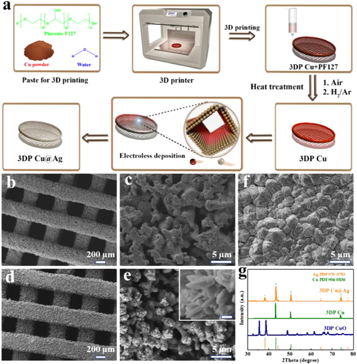
The fabrication procedure of the 3DP Cu@Ag electrode is shown in Fig. 1a. DIW 3D printing is used to design a Cu-based monolith. Before the nanoscale Ag layer plating, the printed 3D Cu skeletons are subjected to two steps of treatment including annealing in air and hydrogen reduction. The steady color change from dark red to grey, and finally to red-orange on the electrode surface clearly indicates the transition from Cu with PF127 to bare Cu as shown in Fig. S1a (Supporting information). After Ag layer plating, a uniform silvery color appears on the 3DP Cu@Ag skeleton, indicating that the Ag plating layer is continuous and homogeneous, which would be beneficial to the dendrite-free Na deposition during the charge-discharge cycling. The air annealing in the air is an indispensable step for the binder removal, not only because F-127 is a poorly conducting polymer that would reduce the electrical conductivity of the monolith, but also because carbon residues derived from the binder after the sintering step would hinder the connection of metal particles, resulting in poor structural integrity [30].
Figure 1
Figure 1.
(a) Schematic illustration for the fabrication process of 3DP Cu@Ag. SEM images of (b, c) 3DP Cu, (d, e) 3DP Cu@Ag, and (f) 2D Cu. (g) XRD patterns of 3DP CuO, 3DP Cu, and 3DP Cu@Ag. White bar of the inset in (e): 200 nm.
The 3D-printed monolith consists of interwoven vertical and horizontal filaments, forming uniformly distributed tunnels (Figs. 1b and d). Various complex patterns can also be achieved through DIW, demonstrating large freedom in the designs of electrode architecture (Fig. S1b in Supporting information). Moreover, lots of small pores appear in the original space occupied by PF-127 in each filament after the elimination of the polymeric binders and can be maintained after the Ag plating as shown in the magnified SEM images (Figs. 1c and e). This well-designed 3D skeleton with a hierarchical porous architecture provides more space for Na growth and possesses a larger specific surface area that can effectively increase the contact with the electrolyte, reduce local current density, and redistribute charges. The inset in Fig. 1e shows the detailed superficial feature of 3D skeleton at high magnification. It can be seen that the Ag nanosheets are deposited closely on the Cu substrate. In contrast, the 2D Cu foil surface (control group) shows massive large and dense grains (Fig. 1f). A chronoamperometry measurement was used to measure the specific electrochemically active surface area. As shown in Fig. S2 (Supporting information), the 3DP Cu@Ag electrode exhibits a larger electrochemically active area and thus provides more sodiophilic sites to induce a homogeneous deposition of Na, as compared to the 2D Cu electrode. Furthermore, the XRD patterns of the three electrodes displayed in Fig. 1g clearly confirm the 3DP electrode transition process from Cu to CuO and finally to Cu@Ag. Characteristic peaks at 38.1°, 44.3°, and 66.4° corresponded to (111), (200), and (220) planes from face-centered cubic Ag (PDF#04–0783) can be observed together with those of metallic Cu (cubic, PDF#04–0836) in the final product. The EDS elemental analysis in Fig. S3 (Supporting information) also proves that the 3DP Cu@Ag consists of Ag and Cu. Therein, the Ag element is homogeneously distributed on the whole 3D-printed skeleton surface. Then, the as-prepared 3DP Cu and 3DP Cu@Ag electrodes were directly used as the current collectors without any other additives for Na metal anodes.
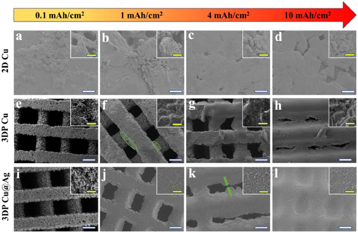
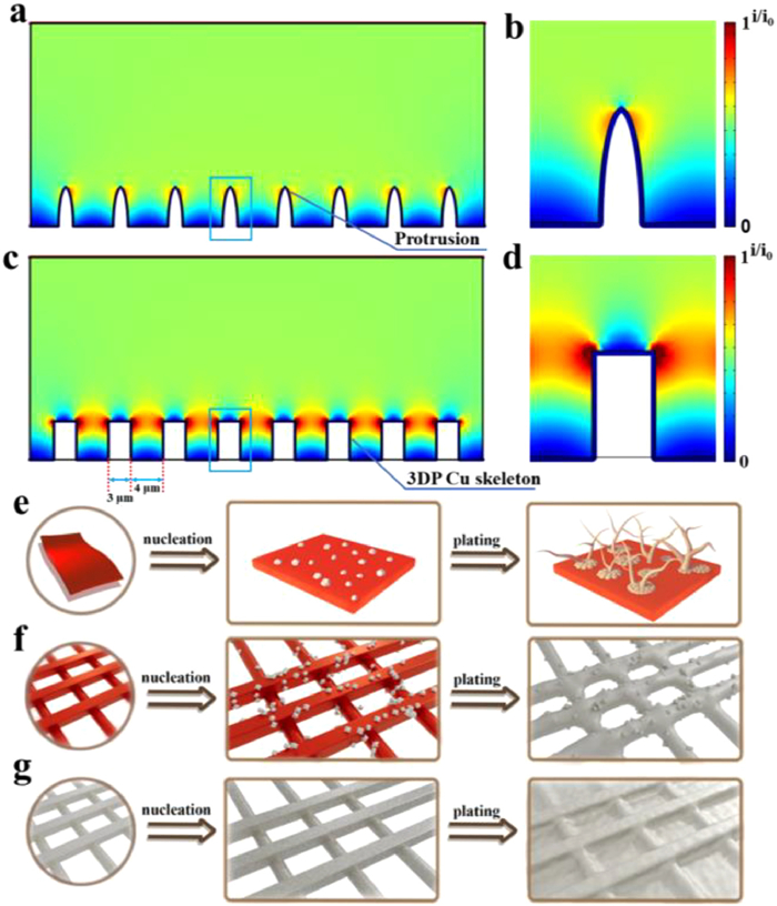
The electrochemical performance is closely correlated to the surface morphology of Na metal formed on the electrode [40]. To study Na deposition behavior on various current collectors, Na morphological evolutions with various capacities at a constant current density of 0.5 mA/cm2 were visually observed by SEM studies (Fig. 2). Since the initial nucleation and deposition have a significant impact on the subsequent plating/stripping stages [9], so a small loading of Na was preferentially deposited onto the electrode with the capacity to be 0.1 mAh/cm2. As shown in Fig. 2a, the 2D Cu electrode was partially covered by irregular deposited Na. Its porous structure can be obviously seen in the inset of Fig. 2a. With the increase of Na deposition to 1 and 4 mAh/cm2, the subsequent Na nucleated on the previously formed Na nuclei and then grew to a larger size (Figs. 2b and c). Furthermore, obvious ravines can also be found on the 2D Cu electrode when capacity reaches up to 10 mAh/cm2 (Fig. 2d). According to the COMSOL simulation results, it is obvious that the protrusions have a higher current density on the surface of 2D Cu, which is in accordance with the theory of lightning rod (Figs. 3a and b) [41,42]. Hence, Na ions tend to accumulate around the top of the protuberance, leading to the notorious "tip effect" harmful to metal electrodeposition [43]. The Na plating on the planar Cu is therefore not homogeneous with either low or high Na loading capacity, which is mainly due to the local charge buildup and the sodiopholic nature of the Cu surface. In addition, the deposited Na expresses a rugged microstructure, rather than the filament-like dendrites on Li metal anodes [44]. As for 3DP Cu electrode, the pristine surface is almost maintained (Fig. 2e) when the Na plating capacity is relatively small (0.1 mAh/cm2). The reason could be that the 3D hierarchical structure provided a larger specific surface area as compared to the 2D Cu, which had reduced the local current density and benefitted the uniform distribution of Na. After plating 1 mAh/cm2 of Na, in addition to growing vertically on the surface of the framework, Na metal is also deposited laterally into the gaps of the skeleton (Fig. 2f), which is consistent with the COMSOL simulation results. The large volume change in Na deposition/stripping is thus inhibited due to the unique merit of the 3D structure. With the capacity being increased to 4 and 10 mAh/cm2, Na continuously grew in the lateral direction but inevitably aggregated with the existed Na in the vertical direction simultaneously (Figs. 2g and h). Several Na nodules merged and gradually became larger ones. Some of them would pierce through the separator and cause safety issues.
Figure 2
Figure 2.
SEM images of Na metal deposited on 2D Cu electrode after plating (a) 0.1 mAh/cm2, (b) 1 mAh/cm2, (c) 4 mAh/cm2, and (d) 10 mAh/cm2. SEM images of Na metal deposited on 3DP Cu electrode after plating (e) 0.1 mAh/cm2, (f) 1 mAh/cm2, (g) 4 mAh/cm2, and (h) 10 mAh/cm2. SEM images of Na metal deposited on 3DP Cu@Ag electrode after plating (i) 0.1 mAh/cm2, (j) 1 mAh/cm2, (k) 4 mAh/cm2, and (l) 10 mAh/cm2. White bar: 300 µm. Yellow bar: 10 µm.
Figure 3.
COMSOL Multiphysics simulations at electrolyte/electrode interphase of (a, b) 2D Cu and (c, d) 3DP Cu@Ag. Schematic illustration of the Na plating behaviors on (e) bare 2D Cu foil, (f) 3DP Cu, and (g) 3DP Cu@Ag electrode.
In contrast, there was little visible change in the 3DP Cu@Ag electrode surface at the low capacity of 0.1 mAh/cm2 (Fig. 2i), which has been benefitted from the synergistic effect of 3D-printed structure and sodiophilic Ag coating. This 3D hierarchical structure not only provides more deposition sites but also leads Na ions to flow into the channels because of the concentrated electric field in the lateral direction. According to the COMSOL simulation results, the current mainly accumulates around the sidewall of Ag skeleton (red region in Figs. 3c and d), which leads to a distinct horizontal growth tendency of Na. In addition, Na ion flux would be guided into the deeper space rather than depleted on top of the 3D-printed skeleton (Fig. S4a in Supporting information). Therefore, the Na can be uniformly deposited throughout the whole monolith. Besides, metallic Ag has a stronger attraction to Na according to previous DFT calculations [45], which helps regulate Na nucleation and growth. More importantly, Ag is sodiophilic that does not alloy with Na, which prevents the Ag layer from peeling off the Cu surface during repeated alloying/dealloying processes, thus inhibiting Na decay in cycling on the sodiophilic interphase [46]. As shown in Fig. S5 (Supporting information), Na element is highly overlapping with Ag. This indicates a highly uniform Na nuclei distribution, which plays a vital role in controlling the following Na plating. Thus, a flat electrode surface can be observed after plating 1, 4, and even 10 mAh/cm2 of Na (Figs. 2j-l). When 6 mAh/cm2 of metallic Na was stripped from the plated skeleton (10 mAh/cm2) in reverse, the 3DP Cu@Ag displayed a dendrite-free morphology and no isolated Na existence can be found (Fig. S6a in Supporting information). After complete stripping of Na, there was no bulk Na residue and an explanate surface recovered again, indicating a high efficiency of Na plating/stripping on this electrode (Fig. S7a in Supporting information). As for the 3DP Cu, the remaining Na metal cannot guarantee an integrated surface and local cracks occur, due to that the random location of the charge centralization (Figs. S6b and S7b in Supporting information). The situation for 2D Cu was even worse (Figs. S6c and S7c in Supporting information). There were lots of Na residues on the bare Cu electrode, which will lead to an irreversible Na consumption and low Columbic efficiency.
In addition to the examination on the initial Na nucleation and deposition behavior, the long-term morphology evolution of plated Na on different hosts was also investigated. SEM studies of 2D Cu, 3DP Cu, and 3DP Cu@Ag electrodes after repeated stripping/plating for 50 cycles at 1 mA/cm2 and 1 mAh/cm2 were performed and the obtained images were shown in Fig. S8 (Supporting information), respectively. As for the 3DP Cu@Ag, its skeleton still retained a smoother surface compared to the 2D Cu electrode with a loose and porous structure, and exhibited no thick and peculiar tree branch-shaped plated Na, which are, however, emerged in the gap space of the 3DP Cu electrode. This type of Na will lose the contact with the matrix and form "dead Na", reducing the capacity of the electrode. Therefore, the 3DP Cu@Ag with excellent plated Na morphology would exhibit the most superior cycling stability, compared the other 2D Cu and 3DP Cu electrodes.
According to the different Na plating behavior shown by SEM and COMSOL simulation results, the Na nucleation and further plating process on the three substrates are described in Figs. 3e-g. Generally, the Na nuclei are sparsely distributed on the surface of the 2D Cu (Fig. 3e). The motion of Na ions would be attracted by the former Na nuclei because of their stronger electric field distribution. Massive isolated Na particles are agglomerated into an uneven island-like morphology and eventually transformed into Na dendrites and mossy Na after several cycles. Due to the unique 3D-printed structure, the Na dendrites growth on the external surface of the 3DP Cu electrode is suppressed (Fig. 3f). However, this substrate cannot maintain a smooth morphology under a large deposition capacity because of uneven initial Na nucleation stemming from the sodiophobic nature of Cu. In contrast, for the 3DP Cu@Ag electrode, the dense Ag layer provides abundant sodiophilic sites and promotes homogeneous Na nucleation at the initial stage (Fig. 3g). When the plating capacity is further raised, the 3D-printed structure plays a key role in diluting current density and redistributing Na ion flux, eventually resulting in uniform Na deposition and dendrite-free morphology.
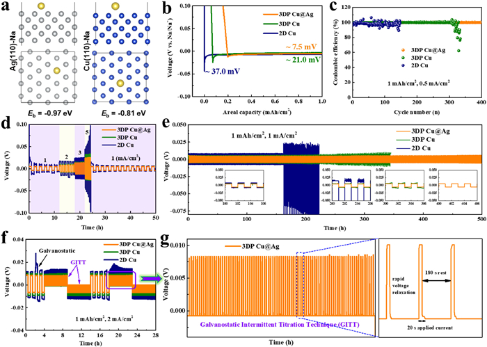
To further explore the electrochemical behavior of 2D Cu, 3DP Cu, and 3DP Cu@Ag electrodes, CR2032 coin cells were assembled and studied by using the above electrodes as the working electrode and Na foil as the counter/reference electrode. Firstly, the cyclic voltammetry (CV) curves of the half cells are compared in Fig. S9 (Supporting information). There is only a pair of cathodic and anodic peaks at around 0 V, which are assigned to be the deposition and dissolution processes of metallic Na, respectively. In contrast to the alloying between Li and Ag, cubic Na only spreads out on the surface of cubic Ag without the formation of a Na-Ag alloying phase because there are no characteristic peaks ascribed to the alloying/de-alloying reaction in the CV curve. It is also evident from the higher current of the CV curves that the Na ion redox kinetics is much faster on the Ag substrate than that on Cu surface [47]. In the inset picture in Fig. S9, Na plating on the Ag surface shows a lower nucleation potential than that on the bare Cu substrate. It may benefit from the stronger binding properties between Ag and Na. Ag nanoscale layer, featured by favorable sodiophilicity and splendid electronic conduction, offers a feasible host toward highly stable batteries. In Fig. 4a, Ag exhibits a larger binding energy of −0.97 eV than that of Cu (−0.81 eV). As expected, the 3DP Cu@Ag showed a lower nucleation overpotential (7 mV) than that of the 3DP Cu (21 mV) or 2D Cu (37 mV) electrode at 0.5 mA/cm2 (Fig. 4b), indicating a reduced polarization in the 3DP Cu@Ag. Its nucleation overpotentials at higher current densities were also tested (Fig. S10 in Supporting information). A low overpotential corresponds to a small nucleation and deposition energy barrier, the value of which is related to the affinity of the Na atom and the matrix as well as the true specific surface area of the electrode [48,49]. Due to the lowest nucleation overpotential, tiny Na seeds would be distributed evenly on the 3DP Cu@Ag current collector, leading to an ultimate dendrite-free morphology.
Figure 4
Figure 4.
(a) Binding energies of Ag−Na and Cu−Na calculated by DFT simulation. (b) Nucleation overpotentials of Na on 2D Cu, 3DP Cu, and 3DP Cu@Ag electrodes at 0.5 mA/cm2. (c) Coulombic efficiencies of different electrodes with the current density of 0.5 mA/cm2 for a total 1 mAh/cm2 of Na. (d) Rate performances of symmetric cells with the capacity limit of 1 mAh/cm2. (e) Voltage profiles of Na plating/stripping in three styles of symmetric cells, that is, 2D Cu@Na, 3DP Cu@Na, and 3DP Cu@Ag@Na cells at 1 mA/cm2 for 1 mAh/cm2. (f) GITT voltage profiles combined with the previous galvanostatic profiles in symmetric cells. (g) GITT voltage profiles of the 3DP Cu@Ag@Na symmetric cell selected from (f).
Another important parameter used to evaluate the utilization of metallic Na during plating/stripping process is the Coulombic efficiency [50]. As displayed in Fig. 4c, the CEs of Na deposition/dissolution on the three electrodes operated at 1 mAh/cm2 and 0.5 mA/cm2 were compared. The 3DP Cu@Ag electrode can remain stable up to 400 cycles, and its average Coulombic efficiency exceeds 99.9%, indicating that there is almost no capacity fading on this electrode. The excellent reversibility and cyclability shall benefit from the inhibition of volume change and dendrites growth. In contrast, the CEs of the 3DP Cu decreased sharply after 300 cycles, and the counterpart of the 2D Cu electrode also fluctuated seriously, which can well be attributed to the porous and uneven growth of Na upon cycling. To evaluate the electrochemical performance of the electrodes at different current densities, we further tested the CEs at the current densities of 1 and 4 mA/cm2 at a fixed capacity of 1 mAh/cm2, respectively. The CEs of 3DP Cu@Ag still maintain a high stability for 300 and 250 cycles with the aid of nanoscale Ag layer and 3D hierarchical structure (Fig. S11 in Supporting information). In contrast, at a higher current density, the uneven depositions of Na on the surface of 2D Cu foil and 3DP Cu electrode are more serious (Fig. S12 in Supporting information). When the deposited capacity was increased to 4 mAh/cm2, the 3DP Cu@Ag cell exhibits a fairly stable CE over 200 cycles whereas the 3DP Cu and 2D Cu both show inferior CEs with unsatisfied cycle lifespan (Fig. S13a in Supporting information). Notably, raising the capacity to 10 mAh/cm2, the 3DP Cu@Ag electrode could be cycled for 100 cycles with a high average Coulombic efficiency of 99.7% (Fig. S13b in Supporting information). This is well due to the inhibition of side reactions, the lateral Na growth, and the large space for accommodating Na volume change. The above results indicate the feasibility of using 3DP Cu@Ag at a high areal capacity or current density condition.
The differences in cyclability of the composite anodes can also be verified by the hysteresis voltages of Na-Na symmetrical cells during cycling. The voltage profiles of different anodes cycled with a fixed capacity of 1 mAh/cm2 and various current densities are shown in Fig. 4d. The 3DP Cu@Ag cell exhibits a flat voltage plateau at each current density and delivers low hysteresis (8.9, 15.6, 25.5, 48.3 mV at 1, 2, 3 and 5 mA/cm2) without discernable fluctuation, demonstrating better rate capability than 3DP Cu and 2D Cu cells (Fig. S14 in Supporting information). The excellent electrochemical performance is attributed to the large surface area provided by the 3D-printed structure and fast charge transfer kinetics stemming from sodiophilic Ag layer of 3DP Cu@Ag. Fig. 4e compared long-term cycling performance of symmetric cells at 1 mA/cm2, 1 mAh/cm2. Encouragingly, both 3DP Cu@Na and 3DP Cu@Ag@Na cells exhibit an extremely low voltage hysteresis (10 mV), much lower than that of the anode with pre-plated Na on 2D bare Cu foil (16 mV) during initiatory cycles. Finally, a stable long-term cycling for more than 500 h is attainable for the 3DP Cu@Ag@Na symmetrical cell. As for the 3DP Cu@Na cell, it can maintain stable voltage profiles in the first 250 h whereas the hysteresis rapidly increased at the same testing condition after that. By contrast, the 2D Cu@Na cell showed a weird voltage profile after 160 h on account of the spatial variation in the electrode/electrolyte interphase and isolated Na accumulation after cycling on the bare Cu surface, which is responsible for the cell failure. It is noteworthy that the electrochemical performances of 3DP Cu@Ag have reached the advanced level of current research for Na metal (Tables S1 and S2 in Supporting information). Na plating/stripping kinetics was further studied by the galvanostatic intermittent titration technique (GITT) experiments combined with common galvanostatic cycles under the minimal mass transport influence (related to the Na ion concentration gradient). The experimental condition of applying charging/discharging current pulse for 20 s and then resting for 180 s until the total plating/stripping capacity reached 1 mAh/cm2 (Fig. 4g) was periodically conducted. As shown in Fig. 4f, the GITT profiles of 3DP Cu@Ag@Na symmetric-cell demonstrate lower overpotential compared to those of 2D Cu@Na and 3DP Cu@Na anodes at the current density of 2 mA/cm2, which proves the enhanced interfacial electrochemical kinetics of the 3DP Cu@Ag@Na anode. Meanwhile, the GITT voltage profiles of 3DP Cu@Ag@Na symmetric-cell are highly similar to those in the earlier galvanostatic cycles, indicating that the voltage profile is not noticeably affected by relaxation due to the fast Na ion diffusion in the 3DP Cu@Ag@Na anode. The interfacial stability of the 3DP Cu@Ag@Na electrode was also tested by EIS measurements (Fig. S15 in Supporting information). The 3DP Cu@Ag@Na electrode exhibited a smaller interfacial impedance than that of Cu@Na after 100 cycles, indicating an improved charge transfer kinetics. In contrast, the interfacial impedance for Cu@Na anode displayed a sharp decrease during cycling, owing to the accumulated SEI and excessive "dead Na" [51,52].
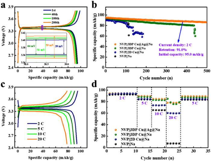
The application feasibility of the composite-type anodes was further explored by investigating electrochemical performances of the full-cell using a homemade NVP as the cathode. Detailed charge–discharge voltage curves of the NVP||3DP Cu@Ag@Na cell at 2 C are shown in Fig. 5a. The voltage hysteresis increases slightly with cycling, but remains low (39, 44, 51 and 59 mV after 1, 40, 100 and 200 cycles, respectively), reflecting the excellent cycling stability of the battery and fast charge transfer kinetics of the 3DP Cu@Ag@Na anode. As shown in Fig. 5b, the long cycling performances of three cells were compared at 2 C. The full-cell with 3DP Cu@Ag@Na anode delivers an initial capacity of 95.0 mAh/g and exhibits superior electrochemical reversibility and stability with a high capacity retention of 91.0% after 500 cycles (0.018% loss per cycle), which markedly surpasses 2D Cu@Na and 3DP Cu@Na counterparts. The improved capacity retention of the NVP||3DP Cu@Ag@Na cell is derived from the smooth plated Na in the composite anode, which is achieved by a uniform sodiophilic Ag nanolayer that acts as Na nucleation sites. Due to the stable interphase and reduced hysteresis of Na deposition/dissolution, the even Na layer in turn evades the subsequent consumption of active Na and electrolyte in the cell. Thus, the cell consisting of 3DP Cu@Ag@Na and NVP could yield better electrochemical performance than that of the NVP||3DP Cu@Na battery. Moreover, when the charging-discharging rate increases from 2 C to 20 C, a remarkable rate performance can still be achieved for the full-cell using 3DP Cu@Ag current collector (Fig. 5c). Specifically, as shown in Fig. 5d, the cell yields highly reversible capacities of 94, 89, 85, and 78 mAh/g at 2, 5, 10, and 20 C, respectively. In contrast, the cell equipped with the 2D Cu@Na anode showed poor rate capability. Its capacity values fade instantly from 93 mAh/g at 2 C to 59 mAh/g at 20 C. After switching back to the 5 C rate, a high specific discharge capacity of 89 mAh/g can still be delivered for the NVP||3DP Cu@Ag@Na cell, suggesting outstanding Na ion redox dynamics with the Ag sodiophilic modification. These promising results all support the unique advantages of 3DP Cu@Ag as anode host for Na metal batteries. We further fabricated a high-capacity NVP cathode and then paired it with the composite-type Na to study cycling stability, which gave a lower N/P ratio of 4.79:1. As shown in Fig. S16 (Supporting information), the initial discharge capacity is 97.0 mAh/g. After 100 cycles, the discharge capacity is still over 90.9 mAh/g (capacity retention of 93.7%), demonstrating a stable cycling performance of this electrode in quasi-practical Na metal batteries.
Figure 5
Figure 5.
(a) Voltage profiles of NVP||3DP Cu@Ag@Na full-cell after different cycles at 2 C. (b) Cycling performance of full cells at 2 C. (c) Voltage profiles of NVP||3DP Cu@Ag@Na full-cell at rates of 2 C, 5 C, 10 C, and 20 C. (d) Rate performances of full cells.
A 3D-printed Cu grid with an improved sodiophilic Ag surface was constructed as the current collector for Na metal anodes by 3D printing and further electroless deposition technique. Ag was selected to lower the nucleation overpotential of Na plating on account of its strong interaction with Na+, which helps to promote a uniform nucleation and deposition behavior of Na, as confirmed by electrochemical investigations. The unique 3D-printed host can not only ameliorate the electric field distribution and induce lateral Na deposition to mitigate the longitudinal stress by virtue of the significantly reduced volume change but also enhance Na nucleation/deposition kinetics. As a result, this electrode exhibits an excellent capacity to regulate the nucleation behavior and suppress Na dendrite growth, achieving a stable Na metal battery with excellent electrochemical performances. The as-prepared Na anode can deliver a long life for more than 400 cycles at the current density of 0.5 mA/cm2 as well as a high CE of 99.9% and also work stably at a high areal capacity of 10 mAh/cm2. Low hysteresis (10 mV at 1 mA/cm2 and 47 mV even at 5 mA/cm2) and long cycling stability (500 h at 1 mA/cm2, 1 mAh/cm2) are realized in the symmetric cell. Remarkably, the assembled NVP||3DP Cu@Ag@Na battery demonstrates a high capacity retention of 91.0% for 500 cycles at 2 C and a significantly improved rate capability (78 mAh/g at 20 C). Our work sheds new light on the effectiveness of the strategy of 3D-printed electrode modified by sodiophilic layer for advanced Na metal anodes.
Declaration of competing interest
The authors declare that they have no known competing financial interests or personal relationships that could have appeared to influence the work reported in this paper.
Acknowledgments
This work was supported by the China Scholarship Council (No. 202006120422), the National Natural Science Foundation of China (Nos. 51874110, 51604089), Natural Science Foundation of Heilongjiang Province (No. LH2021B011), and Open Project of State Key Laboratory of Urban Water Resource and Environment (No QA202138). Authors acknowledge the support by the Singapore Ministry of Education (MOE, No. MOE2018-T2–2–095), for research conducted at the National University of Singapore, and the Green Energy Programme (No. R284–000–185–731) funded by the National University of Singapore.
Supplementary materials
Supplementary material associated with this article can be found, in the online version, at doi:10.1016/j.cclet.2023.109353.
L. Ye, M. Liao, T. Zhao, et al., Angew. Chem. Int. Ed. 131 (2019) 17210–17216. doi: 10.1002/ange.201910202
Figure 1
(a) Schematic illustration for the fabrication process of 3DP Cu@Ag. SEM images of (b, c) 3DP Cu, (d, e) 3DP Cu@Ag, and (f) 2D Cu. (g) XRD patterns of 3DP CuO, 3DP Cu, and 3DP Cu@Ag. White bar of the inset in (e): 200 nm.
Figure 2
SEM images of Na metal deposited on 2D Cu electrode after plating (a) 0.1 mAh/cm2, (b) 1 mAh/cm2, (c) 4 mAh/cm2, and (d) 10 mAh/cm2. SEM images of Na metal deposited on 3DP Cu electrode after plating (e) 0.1 mAh/cm2, (f) 1 mAh/cm2, (g) 4 mAh/cm2, and (h) 10 mAh/cm2. SEM images of Na metal deposited on 3DP Cu@Ag electrode after plating (i) 0.1 mAh/cm2, (j) 1 mAh/cm2, (k) 4 mAh/cm2, and (l) 10 mAh/cm2. White bar: 300 µm. Yellow bar: 10 µm.
Figure 3
COMSOL Multiphysics simulations at electrolyte/electrode interphase of (a, b) 2D Cu and (c, d) 3DP Cu@Ag. Schematic illustration of the Na plating behaviors on (e) bare 2D Cu foil, (f) 3DP Cu, and (g) 3DP Cu@Ag electrode.
Figure 4
(a) Binding energies of Ag−Na and Cu−Na calculated by DFT simulation. (b) Nucleation overpotentials of Na on 2D Cu, 3DP Cu, and 3DP Cu@Ag electrodes at 0.5 mA/cm2. (c) Coulombic efficiencies of different electrodes with the current density of 0.5 mA/cm2 for a total 1 mAh/cm2 of Na. (d) Rate performances of symmetric cells with the capacity limit of 1 mAh/cm2. (e) Voltage profiles of Na plating/stripping in three styles of symmetric cells, that is, 2D Cu@Na, 3DP Cu@Na, and 3DP Cu@Ag@Na cells at 1 mA/cm2 for 1 mAh/cm2. (f) GITT voltage profiles combined with the previous galvanostatic profiles in symmetric cells. (g) GITT voltage profiles of the 3DP Cu@Ag@Na symmetric cell selected from (f).
Figure 5
(a) Voltage profiles of NVP||3DP Cu@Ag@Na full-cell after different cycles at 2 C. (b) Cycling performance of full cells at 2 C. (c) Voltage profiles of NVP||3DP Cu@Ag@Na full-cell at rates of 2 C, 5 C, 10 C, and 20 C. (d) Rate performances of full cells.

 DownLoad:

 下载:
下载:


