Citation:
Haoyuan Lv, Hongbo Guo, Kai Guo, Haitao Lei, Wei Zhang, Haoquan Zheng, Zuozhong Liang, Rui Cao. Substituent position effect of Co porphyrin on oxygen electrocatalysis[J]. Chinese Chemical Letters,
2021, 32(9): 2841-2845.
doi:
10.1016/j.cclet.2021.02.032
Substituent position effect of Co porphyrin on oxygen electrocatalysis
English
Substituent position effect of Co porphyrin on oxygen electrocatalysis
Key Laboratory of Applied Surface and Colloid Chemistry, Ministry of Education, School of Chemistry and Chemical Engineering, Shaanxi Normal University, Xi'an 710119, China
Received Date:
29 December 2020 Accepted Date:
17 February 2021 Revised Date:
07 February 2021 Available Online:
15 September 2021
Abstract:
Substituent effect of metal porphyrin molecular catalysts plays a crucial role in determining the catalytic activity of oxygen electrocatalysis. Herein, substituent position effect of Co porphyrins on oxygen electrocatalysis, including the oxygen reduction reaction (ORR) and the oxygen evolution reaction (OER), was investigated. Two Co porphyrins, namely 2, 4, 6-OMe-CoP and 3, 4, 5-OMe-CoP, were selected as the research objects. The ORR and OER performance was evaluated by drop-coating molecular catalysts on carbon nanotubes (CNTs). The resulted 3, 4, 5-OMe-CoP/CNT exhibited high bifunctional electrocatalytic activities and better long-term stability for both ORR and OER than 2, 4, 6-OMe-CoP/CNT. Furthermore, when applied in the Zn-air battery, 3, 4, 5-OMe-CoP/CNT exhibited comparable performance to that with precious metal-based materials. The enhanced catalytic activity may be attributed to the improved charge transfer rate, mass transfer and hydrophilicity. This work provides an effective strategy to further enhance catalytic activity by introducing substituent position effect, which is of great importance for developing more efficient energy-related electrocatalysts.
Electrocatalytic oxygen reduction reaction (ORR) and oxygen evolution reaction (OER), as important reactions in several new energy conversion technologies, such as fuel cells, metal-air batteries, and water electrolysis devices, have attracted increasing interests [1-12]. Efficient electrocatalysts for ORR and OER are highly required due to the very slow kinetics of the two reactions [13-24]. At present, Pt-based materials [25] and Ru-based oxides [26] exhibited excellent catalytic activity for ORR and OER, respectively. However, the low reserve and high price of these precious metals limit their large-scale applications [27]. Therefore, it is important to design low-cost and efficient catalysts for both ORR and OER.
Inspired from Fe porphyrin of heme in nature, porphyrin-based molecular catalysts have attracted great attention recently for oxygen electrocatalysis [28-36]. The catalytic activity of metal porphyrins can be finely tuned through regulating their structures [37]. Furthermore, the clear and stable molecular structures of metal porphyrins are beneficial for the study of catalytic reaction mechanisms [38-41]. In addition, the resulted structure-function relationships will further guide the design and development of more efficient molecular catalysts [42]. Particularly, the meso-substituent effects have been widely investigated to regulate the catalytic activity of metal porphyrins through tuning electronic structure of metal centers [43]. It is suggested that electron-donating substituents [44], such as -OMe, can increase the electron density of metal centers and thus increases the binding and electron transfer with O2 [45], which is crucial for determining the activity of ORR. Therefore, fine-tuning the meso-substituent structure of metal porphyrins is an appealing strategy to improve the ORR activity.
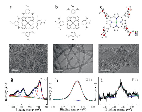
Herein, we designed two Co porphyrin molecular catalysts with three -OMe groups at 2, 4, 6- and 3, 4, 5-positions of meso-phenyl substituents, named 2, 4, 6-OMe-CoP and 3, 4, 5-OMe-CoP (Figs. 1a and b). Molecular structures of these two porphyrins were characterized with nuclear magnetic resonance (NMR), mass spectra (MS), UV–vis, Fourier transform infrared spectrometer (FTIR), and single crystal X-ray diffraction method. Coporphyrin catalysts were drop-coated on carbon nanotubes (CNTs) for oxygen electrocatalysis. The catalytic activity, selectivity, and stability of these two molecular catalysts were evaluated. The 3, 4, 5-OMe-CoP exhibited better ORR performance than 2, 4, 6-OMe-CoP likely due to its enhanced mass transfer, improved charge transfer and hydrophilicity. The OER performance of molecular catalysts and Zn-air battery assembled with 3, 4, 5-OMe-CoP were further evaluated. This work provides a better understanding of the substituent position effect of -OMe groups for Co porphyrin molecular catalysts.
Figure 1
Figure 1.
Molecular structures of (a) 2, 4, 6-OMe-CoP and (b) 3, 4, 5-OMe-CoP. (c) Thermal ellipsoid plot of single crystal X-ray structure of 3, 4, 5-OMe-CoP (50% probability). (d) SEM image and (e, f) TEM images of 3, 4, 5-OMe-CoP/CNT. XPS spectra of 3, 4, 5-OMe-CoP/CNT: (g) Co 2p, (h) O 1s and (i) N 1s.
First, 2, 4, 6-OMe-CoP and 3, 4, 5-OMe-CoP were synthesized and characterized with high-resolution MS, NMR, FTIR, and UV–vis spectra (Fig. 1 and Figs. S1–S5 in Supporting information) [46]. UV–vis spectra of 2, 4, 6-OMe-CoP and 3, 4, 5-OMe-CoP showed Soret and Q bands of Co porphyrins (Fig. S6 in Supporting information), indicating the integrity of the porphyrin structure [47]. Under N2 conditions, cyclic voltammetry (CV) data of 2, 4, 6-OMe-CoP and 3, 4, 5-OMe-CoP were tested in dimethylformamide (Fig. S7 in Supporting information). For 2, 4, 6-OMe-CoP, there is a reversible redox wave and an irreversible redox wave at –1.50 and –2.32 V vs. ferrocene, respectively, corresponding to the CoⅡ/CoⅠ and CoⅠ/Co0 redox couples. In contrast, 3, 4, 5-OMe-CoP has two reversible redox waves at –1.36 and –2.52 V vs. ferrocene, corresponding to the CoⅡ/CoⅠ and CoⅠ/Co0 redox couples, respectively. These peaks of 3, 4, 5-OMe-CoP exhibit anodic shift by about 200 mV comparing to those of 2, 4, 6-OMe-CoP. The crystal structure of 3, 4, 5-OMe-CoP was obtained with single crystal X-ray diffraction (Fig. 1c). The Co ion is coordinated by the four N atoms of the porphyrin unit, which define an equatorial plane. The 3, 4, 5-OMe-CoP crystallized in triclinic space group Pī with Z=2 (Table S1 in Supporting information).
To evaluate the catalytic activity of oxygen electrocatalysis, Co porphyrin molecular catalysts were drop-coated on CNTs, named 3, 4, 5-OMe-CoP/CNT. Scanning electron microscope (SEM) and transmission electron microscope (TEM) images of CNT and 3, 4, 5-OMe-CoP/CNT were obtained (Figs. 1d and f, Fig. S8 in Supporting information). CNT has very good dispersion with a diameter of ~15 nm (Fig. S8). The 3, 4, 5-OMe-CoP/CNT still shows good dispersion (Figs. 1d and f). No obvious aggregated particles were observed on the surface of CNTs, indicating the uniform distribution of Co porphyrins.
In order to verify the central metal valence state of Co porphyrin and the successful loading of molecular catalysts, X-ray photoelectron spectroscopy (XPS) test of 3, 4, 5-OMe-CoP/CNT was carried out. From the full survey spectrum, obvious peaks of Co, O, N and C were observed, demonstrating the successful loading of Co porphyrins (Fig. S9 in Supporting information). The high resolution XPS spectrum of Co 2p confirms that the valence state of Co is CoⅡ (Fig. 1g). From the high resolution XPS spectra of O 1s and N 1s, only one kind of peak was observed in the composite 3, 4, 5-OMe-CoP/CNT, indicating that 3, 4, 5-OMe-CoP has been adsorbed on CNTs (Figs. 1h and i).
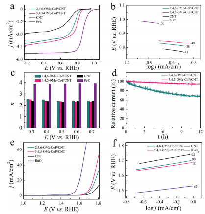
Electrocatalytic activities of 3, 4, 5-OMe-CoP/CNT and 2, 4, 6-OMe-CoP/CNT for ORR were evaluated with rotating disk electrode (RDE) and rotating ring-disk electrode (RRDE) in 0.1 mol/L KOH. The linear sweep voltammetry (LSV) data show that 3, 4, 5-OMe-CoP/CNT exhibits a half-wave potential E1/2 of 0.80 V vs. reversible hydrogen electrode(RHE), which is larger than that of 2, 4, 6-OMe-CoP/CNT with an E1/2 of 0.77 V vs. RHE (Fig. 2a). It is worth noting that both 2, 4, 6-OMe-CoP/CNT and 3, 4, 5-OMe-CoP/CNT exhibited much better ORR performance than CNTs (E1/2=0.70 V vs. RHE), indicating that 2, 4, 6-OMe-CoP and 3, 4, 5-OMe-CoP is the real active site for ORR. In contrast, commercial Pt/C (20 wt%) exhibited an E1/2 of 0.86 V vs. RHE. Tafel slopes for CNTs, 2, 4, 6-OMe-CoP/CNT, 3, 4, 5-OMe-CoP/CNT and Pt/C are 73, 58, 49 and 70 mV/dec, respectively, suggesting fast kinetics and rapid mass transfer of these catalysts (Fig. 2b).
Figure 2
Figure 2.
(a) LSV data, (b) Tafel slopes and (c) electron transfer number of CNT, 2, 4, 6-OMe-CoP/CNT, 3, 4, 5-OMe-CoP/CNT and commercial Pt/C for ORR. (d) Controlled potential electrolysis of 2, 4, 6-OMe-CoP/CNT and 3, 4, 5-OMe-CoP/CNT measured at 0.30 V (vs. RHE) in O2-saturated 0.1 mol/L KOH solution with RDE at 1600 rpm. (e) LSV data and (f) Tafel slopes of CNT, 2, 4, 6-OMe-CoP/CNT, 3, 4, 5-OMe-CoP/CNT and commercial RuO2 for OER measured in 1.0 mol/L KOH with glassy carbon electrode.
Subsequently, the selectivity of ORR was evaluated by measuring the number of electrons transferred with RRDE (Fig. S10 in Supporting information). According to the current density detected at the disk electrode and the ring electrode, the n value was determined to be 2.37 for 2, 4, 6-OMe-CoP/CNT, 2.33 for 3, 4, 5-OMe-CoP/CNT, 2.31 for CNTs and 3.91 for Pt/C (Fig. 2c). These results demonstrated that the ORR of CNTs, 2, 4, 6-OMe-CoP/CNT and 3, 4, 5-OMe-CoP/CNT follows 2e reduction process with the production of H2O2. The values of n were further confirmed by using Koutecky-Levich (K-L) equations (Fig. S11 in Supporting information). In contrast, Pt/C follows 4e reduction process with the production of H2O. Moreover, we carried out the stability test of two molecular catalysts with controlled potential electrolysis. The relative current of 2, 4, 6-OMe-CoP/CNT decreased by 31%, while 3, 4, 5-OMe-CoP/CNT only dropped by 6% after running for 12 h under the applied potential of 0.3 V vs. RHE (Fig. 2d).
The electrocatalytic activity of OER was studied with glassy carbon electrode in 1.0 mol/L KOH solution. The 3, 4, 5-OMe-CoP/CNT has an overpotential η of 482 mV to reach j = 10 mA/cm2, which is smaller than that of 2, 4, 6-OMe-CoP/CNT (η = 500 mV) (Fig. 2e). To obtain the electrochemical surface area (ECSA), the double layer capacitance (Cdl) was calculated first by performing CV data in the Faraday zone with different scan rates (20, 40, 60, 80, 100 and 120 mV/s) (Figs. S12a and b in Supporting information). The results demonstrated that the Cdl of 2, 4, 6-OMe-CoP/CNT is 16 mF, which is larger than that of 3, 4, 5-OMe-CoP/CNT (4 mF) (Fig. S12c in Supporting information). The following Eq. 1 can be applied to calculate the ECSA.
(1)
herein, the specific capacitance Cs for Co-based materials is 2.75 mF/cm2 [48]. Therefore, the ECSA of 3, 4, 5-OMe-CoP/CNT and 2, 4, 6-OMe-CoP/CNT is 1.5 and 5.8 cm2, respectively. The normalized LSV data demonstrated that 3, 4, 5-OMe-CoP/CNT has higher intrinsic activity that 2, 4, 6-OMe-CoP/CNT (Fig. S12d in Supporting information). The turnover frequency (TOF) could be calculated with the Eq. 2:
(2)
herein, J is the current density at a given potential, S is the surface area of electrode, F is the faraday constant (96485.3 C/mol), and n is the number of active sites. The TOF of 3, 4, 5-OMe-CoP/CNT and 2, 4, 6-OMe-CoP/CNT under the overpotential of 550 mV is 20.4 and 12.7 s−1, respectively. In addition, 3, 4, 5-OMe-CoP/CNT displays smaller Tafel slope with a value of 81 mV/dec as compared to the value of 90 mV/dec for 2, 4, 6-OMe-CoP/CNT, 98 mV/dec for CNTs and 67 mV/dec for RuO2 (Fig. 2f). Therefore, 3, 4, 5-OMe-CoP/CNT exhibits better OER performance than 2, 4, 6-OMe-CoP/CNT.
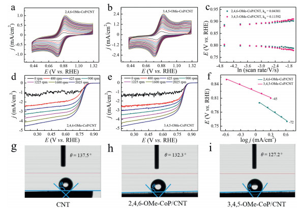
To understand catalytic activity for 3, 4, 5-OMe-CoP/CNT, the electron transfer efficiency, mass transfer rate and hydrophilicity were investigated (Fig. 3). The [Fe(CN)6]3− redox process of 2, 4, 6-OMe-CoP/CNT and 3, 4, 5-OMe-CoP/CNT coated glassy carbon electrode at different scan rates (0.01−0.42 V/s) were carried out in 0.1 mol/L KCl (Figs. 3a and b). The relationship between the position of redox peaks and the logarithm of scan rates was constructed (Fig. 3c). The electron transfer efficiency of the catalyst surface was compared by calculating the surface electron transfer rate constant (ks). The ks value of 3, 4, 5-OMe-CoP/CNT (0.116 s−1) is almost three times larger than that of 2, 4, 6-OMe-CoP/CNT (0.043 s−1), demonstrating that 3, 4, 5-OMe-CoP/CNT has better charge transport ability compared to 2, 4, 6-OMe-CoP/CNT.
Figure 3
Figure 3.
The [Fe(CN)6]3− redox results of (a) 2, 4, 6-OMe-CoP/CNT and (b) 3, 4, 5-OMe-CoP/CNT at different scanning rates (0.01-0.42 V/s) at 0.1 mol/L KCl. (c) The relationship between the position of redox peaks and the logarithm of scan rates. RDE measurements for ORR at RDE electrode loaded with (d) 2, 4, 6-OMe-CoP/CNT and (e) 3, 4, 5-OMe-CoP/CNT at different rotation rates (0, 400, 625, 900, 1225, 1600 and 2025 rpm). (f) Tafel plots based on the kinetic controlled current density. Contact angle test of (g) CNT, (h) 2, 4, 6-OMe-CoP/CNT and (i) 3, 4, 5-OMe-CoP/CNT.
In order to further compare the mass transfer rate of these two catalysts, LSV data of 2, 4, 6-OMe-CoP/CNT and 3, 4, 5-OMe-CoP/CNT were measured at different rotation speeds with RDE (Figs. 3d and e). The kinetic controlled currents at different potentials were made into Tafel diagrams, and then Tafel slopes excluding mass transfer resistance were obtained (Fig. S11). Kinetic controlled Tafel slope of 2, 4, 6-OMe-CoP/CNT is 72 mV/dec, while the value of 3, 4, 5-OMe-CoP/CNT is 45 mV/dec (Fig. 3f). This result indicates that 3, 4, 5-OMe-CoP/CNT has a much higher mass transfer efficiency than that of 2, 4, 6-OMe-CoP/CNT. In other words, 3, 4, 5-OMe-CoP/CNT has very good mass transfer ability.
We further studied the hydrophilicity of these two catalysts and CNTs. Contacting angles of CNTs (Fig. 3g), 2, 4, 6-OMe-CoP/CNT (Fig. 3h) and 3, 4, 5-OMe-CoP/CNT (Fig. 3i) were 137.5°, 132.3° and 127.2°, respectively. This result indicates that 3, 4, 5-OMe-CoP/CNT has relatively good hydrophilic property.
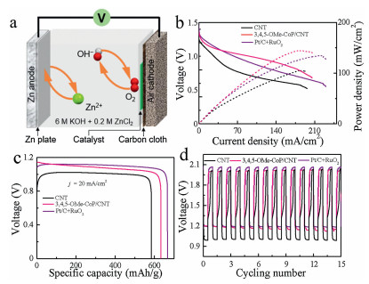
Based on the good electrocatalytic ORR and OER performance of 3, 4, 5-OMe-CoP/CNT, a rechargeable Zn-air battery was assembled using this catalyst. The polished Zn foil was used as the anode, and the catalyst-dropped carbon cloth/gas diffusion layer was used as the cathode (Fig. 4a). The electrolyte was 6.0 mol/L KOH with 0.2 mol/L Zn acetate, to ensure the reversible reactions when charging.Fig. 4b shows the charge and discharge electrochemical polarization data and the corresponding power density data. The 3, 4, 5-OMe-CoP/CNT has the largest power density with a value of 144.8 mW/cm2 compared to that of Pt/C+RuO2 (137.1 mW/cm2) and CNT (106.3 mW/cm2). Fig. 4c displays the discharge characteristic curve of CNT, 3, 4, 5-OMe-CoP/CNT and Pt/C+RuO2 at j = 20 mA/cm2. The specific capacitance of 3, 4, 5-OMe-CoP/CNT is 634.02 mAh/g, which is larger than that of CNT (583.55 mAh/g) and smaller than that of Pt/C+RuO2 (668.21 mAh/g).Fig. 4d shows the charge/discharge cycle data of CNT, 3, 4, 5-OMe-CoP/CNT and Pt/C+RuO2 measured at j = 2 mA/cm2. The discharge/charge voltage is 1.19 V and 1.99 V, respectively, for Zn-air battery assembled with 3, 4, 5-OMe-CoP/CNT. Therefore, the resulted charge/discharge voltage gap is 0.8 V, which is smaller than that of Pt/C+RuO2 (0.87 V) and larger than that of CNT (1.01 V) under the same condition, indicating that the 3, 4, 5-OMe-CoP/CNT exhibits the best charge and discharge performance.
Figure 4
Figure 4.
(a) Schematic illustration of the Zn-air battery. (b) Discharge polarization data and corresponding power density, (c) discharge data at j = 20 mA/cm2, and (d) charge-discharge cycle test at j = 2 mA/cm2 for Zn-air batteries assembled with CNT, 3, 4, 5-OMe-CoP/CNT and Pt/C+RuO2.
In summary, we investigated substituent position effect of Co porphyrin molecular catalysts on both ORR and OER. The 3, 4, 5-OMe-CoP/CNT exhibited an E1/2 of 0.80 V vs. RHE for ORR in 0.1 mol/L KOH and an overpotential of 482 mV (at j = 10 mA/cm2) for OER measured in 1.0 mol/L KOH, which is superior than that of 2, 4, 6-OMe-CoP/CNT with an E1/2 of 0.77 V vs. RHE for ORR and an overpotential of 500 mV (at j = 10 mA/cm2) for OER. The enhanced ORR/OER performance of 3, 4, 5-OMe-CoP/CNT may be attributed to the fast charge transfer, enhanced mass transfer and hydrophilicity. The Zn-air battery constructed with 3, 4, 5-OMe-CoP/CNT exhibited comparable performance with precious metal-based material (Pt/C+RuO2). This work provides new ideas for the design of molecular catalysts with different substituent positions, and has new inspiration for the design of high-performance catalysts for clean energy conversion technology.
Declaration of competing interest
The authors declare that they have no known competing financial interests or personal relationships that could have appeared to influence the work reported in this paper.
Acknowledgments
We are grateful for support from the National Natural Science Foundation of China (Nos. 21808138 and 21773146), Fok Ying-Tong Education Foundation for Outstanding Young Teachers in University, Fundamental Research Funds for the Central Universities (Nos. GK202103029 and GK202103045), Young Talent fund of University Association for Science and Technology in Shaanxi, China, China Postdoctoral Science Foundation (No. 2019T120877), and Research Funds of Shaanxi Normal University.
R. Soury, M. Chaabene, M. Jabli, et al., Chem. Eng. J. 375 (2019) 122005 doi: 10.1016/j.cej.2019.122005
[47]
G. Xu, H. Lei, G. Zhou, et al., Chem. Commun. 55 (2019) 12647-12650 doi: 10.1039/c9cc06916j
[48]
G. Wu, N. Li, D.R. Zhou, K. Mitsuo, B.Q. Xu, J. Solid State Chem. 177 (2004) 3682-3692 doi: 10.1016/j.jssc.2004.06.027
Figure 1
Molecular structures of (a) 2, 4, 6-OMe-CoP and (b) 3, 4, 5-OMe-CoP. (c) Thermal ellipsoid plot of single crystal X-ray structure of 3, 4, 5-OMe-CoP (50% probability). (d) SEM image and (e, f) TEM images of 3, 4, 5-OMe-CoP/CNT. XPS spectra of 3, 4, 5-OMe-CoP/CNT: (g) Co 2p, (h) O 1s and (i) N 1s.
Figure 2
(a) LSV data, (b) Tafel slopes and (c) electron transfer number of CNT, 2, 4, 6-OMe-CoP/CNT, 3, 4, 5-OMe-CoP/CNT and commercial Pt/C for ORR. (d) Controlled potential electrolysis of 2, 4, 6-OMe-CoP/CNT and 3, 4, 5-OMe-CoP/CNT measured at 0.30 V (vs. RHE) in O2-saturated 0.1 mol/L KOH solution with RDE at 1600 rpm. (e) LSV data and (f) Tafel slopes of CNT, 2, 4, 6-OMe-CoP/CNT, 3, 4, 5-OMe-CoP/CNT and commercial RuO2 for OER measured in 1.0 mol/L KOH with glassy carbon electrode.
Figure 3
The [Fe(CN)6]3− redox results of (a) 2, 4, 6-OMe-CoP/CNT and (b) 3, 4, 5-OMe-CoP/CNT at different scanning rates (0.01-0.42 V/s) at 0.1 mol/L KCl. (c) The relationship between the position of redox peaks and the logarithm of scan rates. RDE measurements for ORR at RDE electrode loaded with (d) 2, 4, 6-OMe-CoP/CNT and (e) 3, 4, 5-OMe-CoP/CNT at different rotation rates (0, 400, 625, 900, 1225, 1600 and 2025 rpm). (f) Tafel plots based on the kinetic controlled current density. Contact angle test of (g) CNT, (h) 2, 4, 6-OMe-CoP/CNT and (i) 3, 4, 5-OMe-CoP/CNT.
Figure 4
(a) Schematic illustration of the Zn-air battery. (b) Discharge polarization data and corresponding power density, (c) discharge data at j = 20 mA/cm2, and (d) charge-discharge cycle test at j = 2 mA/cm2 for Zn-air batteries assembled with CNT, 3, 4, 5-OMe-CoP/CNT and Pt/C+RuO2.



 DownLoad:

 下载: