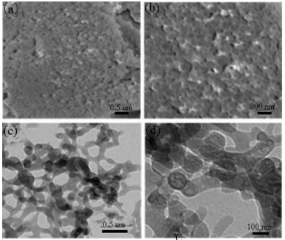
Figure 1.
SEM (a, b) and TEM (c, d) images of the Co/Fe-MOF synthesized in an IL/SC CO2/surfactant emulsion system at 16.5 MPa and 80 ℃ for 48 h.
Fabrication of Fe-doped Co-MOF with mesoporous structure for the optimization of supercapacitor performances
Huanan Yu , Huicong Xia , Jianan Zhang , Jing He , Shiyu Guo , Qun Xu

Owing to their ease of innate high power density and excellent cycling stability, supercapacitors have attracted a great deal of attentions as one of energy storage devices to meet the continuous energy demands and increasing environmental concerns [1-7]. To the best of our knowledge, carbon materials, conducting polymers and transition metal oxides are conventional electrode materials for supercapacitors [8-13]. However, carbon materials usually show the low specific capacitance value in theory while most transition metal oxides exhibit poor pore structure, such as the lack of mesopores and permanent porosity, which restrict their applications on supercapacitor with higher performance [14-16]. Thus, the exploration of new advanced electrode materials with excellent performance for supercapacitors is crucial.
Metal-organic frameworks (MOFs), especially the Co-, Ni-, Znand Cd-based frameworks have received a lot of attentions as the important electrode candidates for supercapacitors, due to their small size, large surface area and uniform pore diameter [17-20]. R. Díaz et al. reported Co8-MOF-5 electrode material for supercapacitors [21]. J. Yang et al. studied the fabrication of Ni-MOF and its electrochemical properties [22]. However, single-metal component is faced with several challenges like bad rate capability and stability [23, 24]. Compared with single-metal material, it has been reported that dual-metal containing materials are capable of higher activity, selectivity and stability in the applications, which can be attributed to the unique "synergies" or "double function mechanism" between different components [25-29]. Thus, fabricating porous hybrid dual-metal MOFs and further efficiently enhancing their electrochemical performance is an interesting work, however, still a big challenge.
In previous work, we devised the ionic liquid (IL)/supercritical CO2 (SC)/surfactant emulsion system to help build multilevel porous Co-MOF [30]. Considering the convenient approach to fabricate highly mesoporous MOF materials, in this paper, we systematically study the electrochemical properties of single metal MOF (Co-MOF and Fe-MOF) and hybrid dual-metal MOF (Co/FeMOF). Experiment results indicate that hybrid Co/Fe-MOF exhibits the highest specific capacitance to 319.5 F/g and best cycle stability with 93.8% of original specific capacitance after 3000 cycles.
In a typical synthesis of Co/Fe-MOF, Fe(NO3)3·9H2O (0.056 g), Co (NO3)2·6H2O (0.060 g), H3BTC (0.042 g), N-ethylperfluorooctylsulfonamide (N-EtFOSA, 0.06 g), and 1, 1, 3, 3-tetramethylguanidinium (TMGA, 0.4 g) were added into a high-pressure cell with a magnetic stirrer. The temperature of the cell was controlled to 80 ℃. Then, CO2 was charged into the cell until 16.5 MPa. After reaction for 48 h, CO2 was released. Finally, the precipitate was collected and washed with ethanol for four times. The synthesis of Fe-MOF and Co-MOF was further described in Supporting information.
Figs. 1a and b are SEM images of hybrid bimetallic Co/Fe-MOF synthesized in an IL/SC CO2/surfactant emulsion system. It presents numerous uniform spherical units with diameter of about 123 nm, 73 and 36 nm bigger than Co-MOF and Fe-MOF, respectively. TEM images of Co/Fe-MOF shown in Figs. 1c and d that these nanospheres connected to each other closely to form a distorted worm-like morphology, so a mass of macropores structure was successfully constructed. The size of macropores differs widely and distributes randomly. Particularly, in Fig. 1d, vast mesopores appear in nanospheres. All in all, we confirmed that hybrid bimetallic Co/Fe-MOF with multilevel pore structure can also be fabricated in the emulsion system. The morphology and microstructure of Fe-MOF were also examined by SEM and TEM. Fig. S1a (Supporting information) shows the Fe-MOF synthesized at 16.5 MPa for 48 h were uniform nanospheres with diameter of about 87 nm.
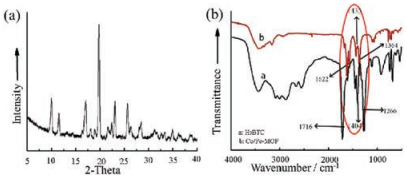
XRD pattern of Co/Fe-MOF (Fig. 2a) shows a series of sharp peaks, which indicates the ordered the Co/Fe-MOF has a good crystallization. As shown in Fig. S2a (Supporting information), through the analysis of XRD diffraction peak intensity and position shift, we determine the crystal structure of Fe-MOF is similar to the data reported in literatures. Besides, there is no other noisy peak of iron oxide phase. In Fourier transform infrared spectrum (Fig. 2b), the ligand H3BTC (1, 3, 5-benzenetricarboxylate) has three major absorption bands of protonated BTC at about 1716 cm-1, 1404 cm-1, and 1277 cm-1. In sharp contrast, the Co/Fe-MOF shows the strong characteristic absorption for the vibration of BTC at about 1623 cm-1, 1440 cm-1, and 1385 cm-1. The wavenumber difference of BTC anions vibration for Co/Fe-MOF is narrowed. It shows that the formed ions in BTC are coordinated to iron and cobalt ions successfully. Based on EDX spectrum and XPS analysis in Fig. S3 in Supporting information, Co, Fe, O and C components are found in Co/Fe-MOF. The characteristic bands at 783.6 eV and 725.4 eV are the fingerprints of Co2p and Fe2p in tetrahedral coordination, implying the persistence of the coordination mode during the phase transformation. The Co2p spectrum of the Co/Fe-MOF can be deconvolved into two spin-orbit doublets [31, 32]. The binding energy at 725.4 eV corresponds to the spin-orbit characteristic of Fe2p [33]. For the Fe-MOF, both EDX and XPS spectra in Fig. S4 (Supporting information) show that Fe, O, and C components are found in Fe-MOF.
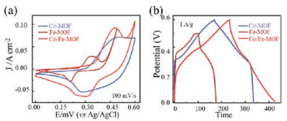
The unique structure of Co/Fe-MOF and Fe-MOF inspired us to examine their electrochemical performances for supercapacitor. CV curves of the three different kinds of MOFs are shown in Fig. 3a. We all know that the computational formula of energy density for supercapacitor is E ∝ V2, where E (Wh/kg) is the energy density and V (V) is working voltage range. As shown in Fig. S5a (Supporting information), the CV curves of Co/Fe-MOF with porous structure were obtained under different scan rates and every CV curve shows a pair of obvious redox peak, indicating that the capacitive property of Co/Fe-MOF electrode is typical pseudocapacitance. Fig. S5b (Supporting information) is constant current charge and discharge curves with current density of 0.5, 1, 2, 5, and 10 A/g. Compared with Co-MOF, the symmetry of every CP curve in Fig. 3b is not good because the electrode materials have high degree of polarization and slow rate for charge/discharge coulomb efficiency. As shown in Fig. S6a (Supporting information), the CV curves of Fe-MOF were obtained under different scan rates. Fig. S6b (Supporting information) is constant current charge and discharge curves with current density of 0.5, 1, 2, 5, and 10 A/g. Fig. S7a (Supporting information) shows the specific capacitance of FeMOF under different current density. In general, it is clear to see higher specific capacitance of Fe-MOF material under lower current density (78 F/g at 0.5 A/g). As the current density rises, however, the specific capacitance value of Fe-MOF declines apparently, which is because high current density can destroy the porous structure of Fe-MOF. Compared with Fe-MOF, the voltage range increases 0.1 V for Co/Fe-MOF, indicating that the coexistence of two components can improve the energy density of MOF material. In addition, the redox peak is more obvious and symmetric than single-metal Co-MOF, which further illustrates that bi-metal components highlight the pseudocapacitive behavior of Co/Fe-MOF. As shown in Fig. 3b, galvanostatic charge-discharge profiles of Co/Fe-MOF shows better symmetry than that of Fe-MOF while longer discharge time than Co-MOF, which is helpful to possess lower polarization and higher charge-discharge columbic efficiency, respectively. As calculated, Co/Fe-MOF has a highest specific capacitance to 319.5 F/g under the same current density 1 A/g (Fig. S8a in Supporting information), 1.4 and 4 times of specific capacitances for Co-MOF and Fe-MOF, respectively.
In fact, the TEM images in Fig. S1, we can see that the nanospheres of Fe-MOF arranged very loosely, thus its stability is bad. Also, it may be due to the coordination bonds between Fe ions and organic ligands are not strong enough, which induces the distortions of Fe-MOF framework under high current density. As supercapacitor electrode, we test the long-term cycling performance of Fe-MOF. The cycle number and the corresponding specific capacitance are shown in Fig. S7b in Supporting information. the specific capacitance maintained a continuous downward trend from the beginning, which demonstrates that FeMOF material has poor cycle stability and this phenomenon is correspond to the analysis. The long-term cycling performance of Co/Fe-MOF is shown in Fig. S8b in Supporting information. After 3000 cycles, hybrid bimetallic Co/Fe-MOF retains 93.8% of the original specific capacitances, proving that electrode material is well stable.
Based on specific capacitances of the Co/Fe-MOF, Fe-MOF, and Co-MOF electrodes at different current densities in Fig. 4a, it is clearly to see hybrid bi-metal Co/Fe-MOF remains highest capacitance value. Cycling stability is also an important index to evaluate the electrochemical performance, as shown in Fig. 4b. Co/ Fe-MOF exhibites best long-term cycling performance with 93.8% of the original specific capacitances after 3000 cycles while FeMOF demonstrates shortest service life with the evident declining trend from the very first. The double components make up for the deficiency of single component (such as short working voltage range and bad cycling stability), at the same time make full use of electrochemical advantages of different metal atoms, showing the synergy between different components.

In summary, hybrid bimetal Co/Fe-MOF with novel hierarchical macro-meso-micro pores was simply fabricated in an SC CO2/IL/ surfactant emulsion system. By taking advantages of the presence of double metal, hybrid bimetal Co/Fe-MOF exhibits highest specific capacitance and best cycling stability, compared with single-metal Co-MOF and Fe-MOF. In short, the coexistence of Co and Fe elements not only optimizes the electrochemical activity of supercapacitor, but also strengthens its stability. This work further expands the application of MOFs in energy storage and conversion field, and inspired us to study the synergy effect between multicomponents.
This work was financially supported by the National Natural Science Foundation of China (Nos. 21571157, U1604123 and 51173170), outstanding Young Talent Research Fund of Zhengzhou University (No. 1521320001), and the Open Project Foundation of Key Laboratory of Advanced Energy Materials Chemistry of Nankai University.
Supplementary data associated with this article can be found, in the online version, at https://doi.org/10.1016/j.cclet.2018.04.008.
C. Liu, Z. Yu, D. Neff, et al., Nano Lett. 10(2010) 4863-4868. doi: 10.1021/nl102661q
T.Y. Wei, C.H. Chen, H.C. Chien, et al., Adv. Mater. 22(2010) 347-351. doi: 10.1002/adma.v22:3
Y. Dou, J. Zhou, F. Yang, et al., J. Mater. Chem. A 4(2016) 12526-12534. doi: 10.1039/C6TA04765C
H. Xia, J. Zhang, Z. Yang, et al., Nano-Micro Lett. 9(2017) 43. doi: 10.1007/s40820-017-0144-6
Z. Yu, L. Tetard, L. Tetard, et al., Energy Environ. Sci. 8(2015) 702-730. doi: 10.1039/C4EE03229B
H. Tang, J. Wang, H. Yin, et al., Adv. Mater. 27(2015) 1117-1123. doi: 10.1002/adma.201404622
Y. Luan, L. Wang, S. Guo, et al., RSC Adv. 5(2015) 42430-42437. doi: 10.1039/C5RA05688H
K. Wang, J. Zhang, W. Xia, et al., J. Mater. Chem. A 3(2015) 18867-18873. doi: 10.1039/C5TA04632G
Y. Li, W. Xia, R. Zou, et al., RSC Adv. 5(2015) 96580-96586. doi: 10.1039/C5RA18624B
K. Wang, H. Wu, Y. Meng, et al., Small 10(2014) 14-31. doi: 10.1002/smll.201301991
P. Shang, J. Zhang, W. Tang, et al., Adv. Funct. Mater. 26(2016) 7766-7774. doi: 10.1002/adfm.v26.43
C. Yuan, H.B. Wu, Y. Xie, et al., Angew. Chem. Int. Ed. 53(2016) 1488-1504. doi: 10.1007/s12274-016-1394-1
S. Wang, J. Zhang, P. Shang, et al., Chem. Commun. 50(2014) 12091-12094. doi: 10.1039/C4CC04832F
L.L. Zhang, X.S. Zhao, Chem. Soc. Rev. 38(2009) 2520-2531. doi: 10.1039/b813846j
P. Simon, Y. Gogotsi, Nat. Mater. 7(2008) 845-854. doi: 10.1038/nmat2297
D.J. Suh, T.J. Park, Chem. Mater. 8(1996) 509-513. doi: 10.1021/cm950407g
M.A. Nasalevich, R. Becker, E.V. Ramos-Fernandez, et al., Energy Environ. Sci. 8(2015) 364-375. doi: 10.1039/C4EE02853H
G.J. Ren, Z. Chang, J. Xu, et al., Chem. Commun. 52(2015) 2079-2082.
Y. Kim, R. Haldar, H. Kim, et al., Dalton Trans. 45(2016) 4187-4192. doi: 10.1039/C5DT03710G
Z. Yue, Z. Chen, M. Yao, et al., RSC Adv. 4(2014) 33537-33540. doi: 10.1039/C4RA04803B
R. Díaz, M.G. Orcajo, J.A. Botas, et al., Mater. Lett. 68(2012) 126-128. doi: 10.1016/j.matlet.2011.10.046
J. Yang, P. Xiong, C. Zheng, et al., J. Mater. Chem. A 2(2014) 16640-16644. doi: 10.1039/C4TA04140B
R.R. Salunkhe, J. Tang, Y. Kamachi, et al., ACS Nano 9(2015) 6288-6296. doi: 10.1021/acsnano.5b01790
J. Yang, C. Zheng, P. Xiong, et al., J. Mater. Chem. A 2(2014) 19005-19010. doi: 10.1039/C4TA04346D
S. Guo, X. Zhang, W. Zhu, et al., J. Am. Chem. Soc. 136(2014) 15026-15033. doi: 10.1021/ja508256g
M.W. Louie, A.T. Bell, J. Am. Chem. Soc. 135(2013) 12329-12337. doi: 10.1021/ja405351s
J.A. Villajos, G. Orcajo, C. Martos, et al., Int. J. Hydrogen Energy 40(2015) 5346-5352. doi: 10.1016/j.ijhydene.2015.01.113
X. Wu, L. Jiang, C. Long, et al., Adv. Funct. Mater. 25(2015) 1648-1655. doi: 10.1002/adfm.201404142
S. Liu, S. Guo, S. Sun, et al., Nanoscale 7(2015) 4890-4893. doi: 10.1039/C5NR00135H
H. Yu, D. Xu, Q. Xu, Chem. Commun. 51(2015) 13197-13200. doi: 10.1039/C5CC04009D
H. Xia, K. Li, Y. Guo, et al., J. Mater. Chem. A (2018), doi:http://dx.doi.org/ 10.1039/C8TA00689J.
Y. Liu, J. Zhang, S. Wang, et al., New J. Chem. 38(2014) 4045-4048. doi: 10.1039/C4NJ00816B
J. Zhang, K. Wang, Q. Xu, et al., ACS Nano 9(2015) 3369-3376. doi: 10.1021/acsnano.5b00760

Figure 1 SEM (a, b) and TEM (c, d) images of the Co/Fe-MOF synthesized in an IL/SC CO2/surfactant emulsion system at 16.5 MPa and 80 ℃ for 48 h.

Figure 2 (a) XRD pattern of Co/Fe-MOF. (b) Fourier transform infrared spectra of the ligand H3BTC and Co/Fe-MOF. All samples were synthesized at 16.5 MPa and 80 ℃ for 48 h.

Figure 3 (a) CV curves of the Co-MOF, Fe-MOF and Co/Fe-MOF electrodes at the scan rate of 100 mV/s. (b) Galvanostatic charge-discharge profiles of the three MOFs at current densities of 1 A/g.

 扫一扫看文章

扫一扫关注我们
 DownLoad:
 下载:
下载:
