Citation:
Qianyu Qiao, Yao Chen, Yue Wang, Yuqing Ren, Jiazhen Cao, Fengjiao Huang, Zhenfeng Bian. Surface modification of phosphate ion to promote photocatalytic recovery of precious metals[J]. Chinese Chemical Letters,
2023, 34(2): 107394.
doi:
10.1016/j.cclet.2022.03.117
Surface modification of phosphate ion to promote photocatalytic recovery of precious metals
English
Surface modification of phosphate ion to promote photocatalytic recovery of precious metals
MOE Key Laboratory of Resource Chemistry and Shanghai Key Laboratory of Rare Earth Functional Materials, Shanghai Normal University, Shanghai 200234, China
b.
Department of Chemistry, Shanghai Key Laboratory of Molecular Catalysis and Innovative Materials, Fudan University, Shanghai 200438, China
* Corresponding author. E-mail address: bianzhenfeng@shnu.edu.cn (Z. Bian). 1 These authors contributed equally to this work.
Received Date:
08 January 2022 Accepted Date:
30 March 2022 Revised Date:
19 February 2022 Available Online:
15 February 2023
Abstract:
Photocatalytic recovery, a novel precious metal recycling technology, dedicates to solving the environmental and energy consumption problems caused by traditional technologies. The activation of molecular oxygen (O2) is one of the most critical steps in the whole process. Herein, we regulated the different adsorption intensity of oxygen on the surface by designing phosphate (PO43−) modified titanium oxide (TiO2). The results show that the adsorption of oxygen on the photocatalyst surface is gradually enhanced, which effectively improves the dissolution rate of precious metals. PO43− modification increased the photocatalytic dissolution rate of gold (Au) by 2.8 times. The photocatalytic activity of other precious metals dissolution (such as palladium (Pd), platinum (Pt), rhodium (Rh), ruthenium (Ru) and iridium (Ir)) was also significantly improved. It is applied to the recovery of precious metals from spent catalysts and electronic devices to significantly promote the recovery efficiency. This indicates the direction for designing more efficient photocatalysts for precious metal recovery.
Being a green environmental remediation method, the photocatalysis technology has emerged among many advanced oxidation process [1-4]. Traditionally, photocatalytic oxidation has been widely used in pollutant degradation [5-9], air purification [10-13], sterilization [14-16], and water splitting [17-21]; recently, our group has introduced an innovative photocatalytic technology in the field of precious metal recovery [22]. With the development of waste resources, the recovery of precious metals in secondary resources has gradually attracted increasing attention [23-28]. In this work, we focus on the dissolution of precious metals, which is a challenging process due to the strong chemical inertness of precious metals.
The technology that is currently being used to dissolve precious metals is mainly based on aqua regia and cyanidation, both of which require high-risk experimental conditions and cumbersome procedures [29-34]. Furthermore, traditional technologies are prone to generate a large amount of secondary waste, and they cannot be used in all situations [26]. There is an urgent need for an environmentally friendly and efficient precious metal dissolution technology [34-36]. In a previous work, we used the superoxide radical (·O2−) derived from photogenerated electrons and coordination components to promote the delocalized oxidation of the outer electrons in precious metals [22]. Seven types of precious metals can be dissolved using a photocatalyst without the need for any acid, alkali, nor cyanide.
To render the photocatalytic dissolution technology more suitable for industrial application, it is necessary to increase the dissolution rate of precious metals. Only by identifying the key active species in the reaction process can the reaction rate of the rate-determining step be accurately improved [37-41]. In preliminary explorations of the mechanism, we believed that ·O2− and photogenerated electron–hole pairs are indispensable active substances for the dissolution of precious metals. Therefore, inhibiting the photogenerated electron–hole recombination or increasing the production of ·O2− may be an effective strategy to accelerate the dissolution of precious metals.
Phosphate particles can interact with hydroxyl groups and be strongly adsorbed on the surface of TiO2, which can significantly affect the interface and surface chemical properties of TiO2. On the one hand, phosphate has a good adsorption effect on O2. On the other hand, phosphate decorated made the surface of TiO2 nanoparticles negatively charged and promoted the migration of photogenerated holes to the surface of the photocatalyst. In the dissolution of precious metals, we need more O2 to participate in the reaction and reduce the recombination of photogenerated e− and h+, so phosphate decorated TiO2 was chosen as catalyst. Based on these considerations, we prepared different salt-decorated TiO2 materials and used them in the photocatalytic dissolution of precious metals. It is worth noting that decorating with PO43− can effectively improve the photocatalytic dissolution efficiency (by 1.2–2.8 times compared with that of undecorated TiO2). This is attributed to the dual functionality of PO43−, which can not only adsorb more oxygen molecules on the catalyst surface to promote the generation of ·O2− but also suppress the recombination of electrons and holes in TiO2. However, optimizing the oxygen adsorption or carrier separation alone cannot accelerate the dissolution of precious metals. In order to increase the photocatalytic dissolution rate of precious metals, the two abovementioned approaches must be combined. Phosphate-loaded TiO2 can be used for the recycling of precious metals from central processing unit (CPU) boards or various waste catalysts, and the proposed strategy is feasible and can be expanded in the future.
Phosphate-loaded TiO2 (P-TiO2) was synthesized using the one-step impregnation method. Firstly, a certain amount of Na3PO4 was added to 40 mL of deionized water to prepare the PO43 precursor. The preparation of 4% P-TiO2 requires 5.26 g of Na3PO4. Different P-TiO2 ratios reduce the Na3PO4 content. Then, 400 mg of commercial TiO2 (P25) was added to form a milky white solution, which was kept at 75 ℃ for 4 h. The white precipitate produced was collected through centrifugation and dried at 80 ℃ in an oven for 12 h. An undecorated P25 sample was utilized for comparison and labeled TiO2. Different phosphate-loaded P25 materials were prepared following the abovementioned preparation steps, and only the phosphate source was replaced for the different samples. We analyzed different contents of P-TiO2 by SEM EDS, where the P contents of 1%, 2%, 3% and 4% P-TiO2 were as 1.10%, 2.08%, 2.70% and 4.54%, respectively (Table S1 in Supporting information). In addition, the P decorating results were quantificationally obtained in Table S2 (Supporting information) by Eq. 1, which was consistent with Table S1.
(1)
The Au NPs were prepared by the sodium citrate reduction method [42]. First, 1% sodium citrate aqueous solution was prepared by 1 g sodium citrate and 100 mL DI. Then, 1 mL HAuCl4 (10 mg/L) and 99 mL DI were boiled in the oil bath pan. After the solution was boiled to 100 ℃, 5 mL of 1% sodium citrate solution was dropped expeditiously, and continued boiling for 10 min to obtain Au NPs.
Take a certain amount of pre-prepared Au NPs and 1 g SiO2 into a 250 mL round-bottomed flask. In a rotary steamer, place the mixture at 80 ℃ and spin-evaporate the solvent at a speed of 60 rpm to prepare Au/SiO2. The Au content in Au/SiO2 dissolved in aqua regia was tested by inductive coupled plasma emission spectrometer to detect the Au loading.
Disperse 50 mg of photocatalyst and 50 mg of 1 wt% Au/SiO2 in a 50 mL quartz bottle containing 20 mL of organic mixed solution (15 mL CH3CN and 5 mL CH2Cl2). Under 500 rpm stirring, put it under UV LED lamp to react (365 nm, 800 mW/cm2). Take samples every 20 min to test the dissolved amount of Au. The photocatalytic dissolution efficiency is calculated according to the actual detected metal content by the inductively coupled plasma spectrometer, and the dissolution rate was calculated according to Eq. 2 below:
(2)
This photocatalytic process is fluid–solid heterogeneous reaction and is commonly described by the shrinking-nucleus model (Eq. 3) [43, 44]:
(3)
where kc represents the apparent rate constants (min−1) for diffusion through the product layer chemical reaction and t is the reaction time, the leaching fraction of precious metal x = Mt/M0, where M0 is the mass of precious metal and Mt is the mass of precious metal in the leached solution.
The dissolution method of other precious metals is the same as above, just change the dissolving object. Since Rh cannot be dissolved in aqua regia, Rh is dissolved in the hydrofluoric acid. And phosphate and silver (Ag) easily form silver phosphide precipitates, so the dissolution of Ag is not considered here.
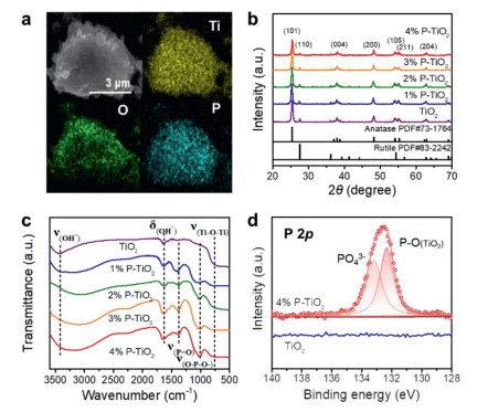
PO43− modified TiO2 was obtained through a simple solution impregnation with P25. Firstly, we focused on P25 loaded with 4% Na3PO4, which is here referred to as 4% P-TiO2. It can be seen from the SEM image that the size and morphology of the sample did not change after the incorporation of PO43− (Figs. S1a and b in Supporting information). The P element is evenly distributed on the surface of the material loaded with PO43− (Fig. 1a). No change occurs in the lattice fringes of the modified P25 (Figs. S1c and d in Supporting information). From the XRD patterns of the catalysts with different decorating contents, it can also be demonstrated that the incorporation of PO43− has no effect on the crystal structure of TiO2 (Fig. 1b). The catalyst peaks in the Raman spectra are found at 145.6, 196.8, 398.5, 517.8 and 638.1 cm−1 and thus have the same location as the TiO2 peaks [45], further confirming that the incorporation of PO43− does not affect the crystal structure of TiO2 (Fig. S2 in Supporting information). Furthermore, it is clear from the FTIR spectra that PO43− was successfully loaded on the surface of TiO2. Compared with pure TiO2, 4% P-TiO2 exhibits new peaks located at 1010–1250 cm−1 and 1260–1320 cm−1, which are attributed to the tensile vibrations of Ti–O–P–O− and P=O, respectively (Fig. 1c) [46-48]. The XPS spectra confirm the combination of P (PO43−) and O (TiO2) in the catalyst. In addition to the characteristic peak of PO43− in the P 2p spectrum at 133.18 eV, a peak corresponding to the P–O bond between P and TiO2 can also be found at 132.38 eV (Fig. 1d) [49]. The Ti 2p3/2 and Ti 2p1/2 peaks for 4% P-TiO2 are located at 457.9 eV and 463.6 eV, signifying the dominant state of Ti4+. Moreover, the high-resolution XPS result definitely confirms existence of Ti–O–P based on the peaks at 459.7 eV and 464.8 eV (Fig. S3a in Supporting information). In the O 1s spectrum of 4% P-TiO2, the peak for the Ti-O bond in TiO2 has been observed at 529.1 eV. Note that the peaks at 530.1 eV corresponded to the oxygen species Ti-O-P and P=O, and the peak at 530.8 eV was assigned to P–O–H (Fig. S3b in Supporting information). The high-resolution P 2p spectrum also confirms the presence of P–O–Ti and PO43− (Fig. S3c in Supporting information). The Na 1s of the 4% P-TiO2 is located at 1071.4 eV (Fig. S3d in Supporting information) [50]. In addition, the zeta potential of 4% P-TiO2 remains always negative in the pH range of 2–13, indicating that the catalyst surface has negatively charged ions (PO43−) (Fig. S4 in Supporting information).
Figure 1
Figure 1.
Catalyst structure and morphology characterization. (a) SEM-EDS mapping of 4% P-TiO2. (b) XRD pattern and (c) FTIR spectra of the different decorated amounts of P-TiO2 sample. (d) The P 2p XPS spectra of 4% P-TiO2 and TiO2.
We then focused on the as-prepared 1 wt% Au/SiO2 sample to explore the catalytic activity of P-TiO2. Au is uniformly loaded on the surface of SiO2 (Fig. S5 in Supporting information). Through a series of optimization experiments, it was found that the catalyst activity of P-TiO2 is the best when the sample is immersed in an Na3PO4 aqueous solution (pH 13) at 75 ℃ for 4 h (Fig. S6 in Supporting information). To explore the effect of Na+ on the dissolution of precious metals, we chose sodium nitrate (NaNO3), which does not adsorb oxygen and does not react with precious metals, as the source of Na+. When different concentrations of NaNO3 solutions (0.01–1 mol/L) were added during the photocatalytic dissolution of Au, the dissolution rate of Au did not change significantly (Fig. S7 in Supporting information). Therefore, the addition of Na+ will not affect the dissolution effect of precious metals. In fact, when the concentration of Na3PO4 solution reaches 0.8 mol/L, the solution is saturated. In saturated Na3PO4 solution, the single maximum loading of PO43− is 4%. After modified P-TiO2 several times, the results showed that the PO43− content on TiO2 was not enhanced even after multiple dipping, and thus the dissolution efficiency was not significantly improved (Fig. S8 and Table S3 in Supporting information). Therefore, the activity of precious metal dissolution does not continue to increase when PO43− doping exceeds 4%. The higher the PO43− content, the faster the dissolution of the precious metals; this may be due to the increase in the number of PO43− active sites on the TiO2 surface (Fig. 2a). From the reaction kinetic curve, it can be observed that the dissolution rate of 4% P-TiO2 is 2.8 times higher than that of TiO2 (Fig. 2b). Over a period of 240 min, the performance of 4% P-TiO2 was found to be 1.8 times higher than that of pure TiO2 for the dissolution of 5% Pt/C, 1.4 times higher for the dissolution of 5% Pd/C, 1.3 times higher for the dissolution of 5% Rh/C, 1.2 times higher for the dissolution of 5% Ru/C, and 1.2 times higher for the dissolution of 5% Ir/C (Figs. 2c–f).
Figure 2
Figure 2.
Photocatalytic dissolution test of precious metals. (a) Dissolution percentage and (b) kinetic linear fitting curves of Au with different photocatalysts. (c) Dissolution percentage and (d) kinetic linear fitting curves of Pd, Pt, Ru, Rh and Ir using TiO2. (e) Dissolution percentage and (f) kinetic linear fitting curves of Pd, Pt, Ru, Rh and Ir using 4% P-TiO2. Reaction conditions: solution (20 mL, CH3CN: CH2Cl2 = 3:1), 50 mg catalyst, 50 mg Au/SiO2, 500 rpm/min, 365 nm LED lamp (800 mW/cm2) in air condition.
The increase in the dissolution rate of precious metals originates from the increase in the number of reactive species. The photocatalytic dissolution of precious metals is a typical photochemical reaction; thus, photogenerated electron–hole pairs are essential active substances. In addition, the capture experiment proved that the ·O2− produced by the reaction between O2 and electrons is a reactive radical species (Figs. 3a and b). The free radicals in the dissolution process were detected via ESR, and the results show that 4% P-TiO2 results in a higher ·O2− content than TiO2 (Fig. 3c). Since the PO43− on the catalyst surface is beneficial for the adsorption of O2, the higher the PO43− content, the larger the amount of O2 chemisorbed on the catalyst surface, and the higher the number of ·O2− generated (Fig. 3d). The mechanism through which P-TiO2 increases the photocatalytic dissolution rate of precious metals is as follows (Fig. 3e). Firstly, the light excites the catalyst, which leads to the generation of electrons and holes, while the PO43− on the catalyst adsorbs a large number of oxygen molecules. Then, the electrons migrate toward the surface of the catalyst and combine with the oxygen molecules, which results in the generation of ·O2−. The holes react with the organic molecules in the solvent to generate organic free radicals. Finally, the free radicals interact with the precious metals and dissolve them.
Figure 3
Figure 3.
(a) Dissolution profile and (b) kinetic linear fitting curves of Au under the capture of different living species (DDQ capture electrons (e−), EDTA-2Na capture holes (h+), p-benzoquinone capture superoxide radical (·O2−)). (c) ESR test for ·O2− species. (d) O2-TPD of TiO2 and x% P-TiO2. (e) Mechanism of P-TiO2 activated oxygen enhancing photocatalytic precious metal dissolution. Reaction conditions: solution (20 mL, CH3CN: CH2Cl2 = 3:1), 50 mg catalyst, 50 mg Au/SiO2, 500 rpm/min, 365 nm LED lamp (800 mW/cm2) in air condition.
Theoretical calculations were conducted to simulate the movement of O2 on the surfaces of TiO2 and P-TiO2 (Fig. S9 in Supporting information). In the simulations involving the O2 adsorption on the TiO2 and P-TiO2 surfaces, the adsorption energy was defined as ΔEad [ΔEad = ETiO − ETiO − Esub)]. During the TiO2 catalysis, the O atoms in O2 are adsorbed on TiO2 and connect with the Ti atoms, forming a bond with a length of 1.976 Å. However, PO43− has a stronger adsorption capacity for oxygen (Table S4 in Supporting information). The bond lengths between the Ti atoms in TiO2 and the O atoms in O2 and the P atoms in PO43− and the O atoms in O2 are 1.979 and 3.116 Å, respectively.
On the other hand, the PO43− incorporation on TiO2 causes the TiO2 surface to be negatively charged (Fig. S4), which favors the migration of photogenerated holes toward the catalyst surface, thereby promoting the separation of photogenerated electrons and holes. In Fig. S10 (Supporting information), transient photocurrent responses and electrochemical impedance spectroscopy (EIS) Nyquist plots of different decorated amounts of (0%−4%) P-TiO2 show that the photocurrent is higher and the impedance is lower with the increasing of PO43− decorated amounts, which further confirms that the charge carrier separation is enhanced after the PO43− decoration. The time-resolved spectroscopic data confirm that 4% P-TiO2 has a longer carrier life (τPL = 0.7556 ns) than TiO2 (τPL = 0.7122 ns) (Fig. S11 in Supporting information). The dissolution reaction rate cannot be increased significantly when other salts (such as NaBr and NaCl) replace PO43−. It can be found that, compared with TiO2, decorating with NaBr can increase the separation between photogenerated charges; however, NaBr has a weaker O2 adsorption. On the other hand, NaCl can absorb more O2, but decorating with NaCl does not result in a significant separation of the photogenerated carriers (Fig. S12 in Supporting information). Therefore, in order to achieve a high-efficiency dissolution of precious metals, it is necessary to increase the yield of ·O2− and the separation of the photogenerated carriers at the same time.
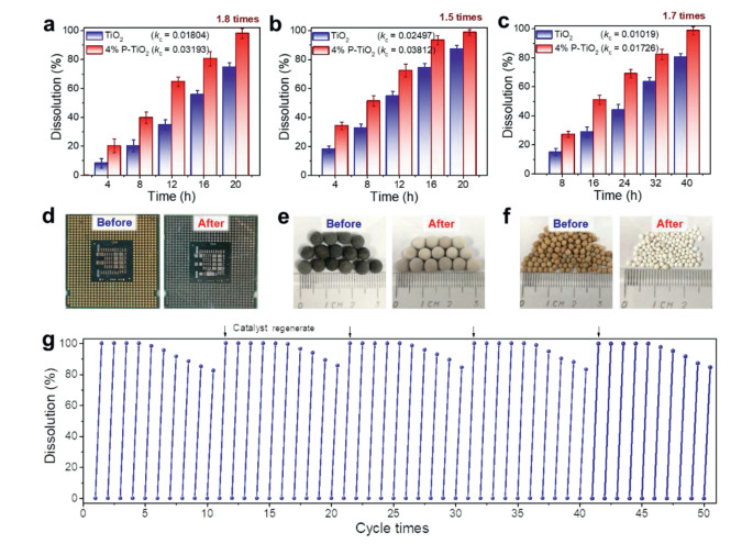
To verify the applicability of P-TiO2, we selected representative CPU boards (containing Au), Pt/SiO2, and Pd/molecular sieves for investigation. The dissolution rates of 4% P-TiO2 for the CPU board, Pt/SiO2, and Pd/molecular sieve are 1.8, 1.5 and 1.7 times higher than those of TiO2, respectively (Figs. 4a–c). Before the reaction, the CPU board, Pt/SiO2, and Pd/molecular sieve were characterized by golden yellow, gray–black, and yellow–brown colors, respectively; after dissolution, the precious metals detached from the carrier, causing the colors to fade (Figs. 4d–f). Not only 4% P-TiO2 exhibits a reasonably good universality, but it also has a good stability. Since PO43− only adheres to the surface of TiO2via electrostatic adsorption, agitation during the reaction may cause the active sites to detach. In the cyclic experiment, the activity of 4% P-TiO2 decreased only by around 20% after 10 continuous cycles (Fig. 4g). From the SEM mapping, it can be found that the content of the P element on the surface of the catalyst is slightly reduced after the reaction (Fig. S13 and Table S1 in Supporting information). As we placed the deactivated catalyst again into the Na3PO4 solution for regeneration, the catalyst resumed its original activity. This confirms that the investigated catalyst can be used in practical applications.
Figure 4
Figure 4.
Photocatalytic dissolution diagram of precious metals from (a) CPU board, (b) Pt/SiO2 and (c) Pd/molecular sieve. Photographs of retrieving precious metals from (d) CPU board, (e) Pt/SiO2 and (f) Pd/molecular sieve before and after reaction. (g) Cycle stability test of 4% P-TiO2. Reaction conditions: Solution (60 mL, CH3CN: CH2Cl2 = 3:1), 1.0 g catalyst, 1.0 g precious metal material, 500 rpm/min, 365 nm LED lamp (800 mW/cm2) in air condition.
In this work, we used a simple one-step method to prepare P-TiO2. Through the design and control of the catalyst surface interface, PO43− was selected among various salts. This catalyst can not only promote the separation of photogenerated electrons and holes but also adsorb more oxygen molecules. Due to this dual functionality, the generation of ·O2− is enhanced, which improves the efficiency of the photocatalytic dissolution of precious metals. This simple catalyst can be prepared at low cost, and offers the possibility to enhance the photocatalytic recovery of precious metals.
Declaration of competing interest
The authors declare no competing interests.
Acknowledgments
This work was supported by the National Key Research and Development Program of China (No. 2020YFA0211004), the National Natural Science Foundation of China (Nos. 22176128, 21876114), Sponsored by Program of Shanghai Government (Nos. 21XD1422800, 19DZ1205102, 19160712900), Chinese Education Ministry Key Laboratory and International Joint Laboratory on Resource Chemistry, and Shanghai Eastern Scholar Program. "111 Innovation and Talent Recruitment Base on Photochemical and Energy Materials" (No. D18020), Shanghai Engineering Research Center of Green Energy Chemical Engineering (No. 18DZ2254200). Shanghai Frontiers Science Center of Biomimetic Catalysis.
Supplementary materials
Supplementary material associated with this article can be found, in the online version, at doi:10.1016/j.cclet.2022.03.117.
[1]
M. Coha, G. Farinelli, A. Tiraferri, et al., Chem. Eng. J. 414 (2021) 128668. doi: 10.1016/j.cej.2021.128668
[2]
Y. Shang, X. Xu, B. Gao, et al., Chem. Soc. Rev. 50 (2021) 5281–5322. doi: 10.1039/d0cs01032d
[3]
P. Sun, T. Meng, Z. Wang, et al., Environ. Sci. Technol. 53 (2019) 9024–9033. doi: 10.1021/acs.est.9b00749
[4]
Z.H. Xie, H.Y. Zhou, C.S. He, et al., Chem. Eng. J. 414 (2021) 128713. doi: 10.1016/j.cej.2021.128713
[5]
R. Dhawle, D. Mantzavinos, P. Lianos, Appl. Catal. B: Environ. 299 (2021) 120706. doi: 10.1016/j.apcatb.2021.120706
M. Kang, Y. Ruan, Y. Lu, et al., J. Mater. Chem. A 7 (2019) 16937–16946. doi: 10.1039/c9ta05299b
Figure 1
Catalyst structure and morphology characterization. (a) SEM-EDS mapping of 4% P-TiO2. (b) XRD pattern and (c) FTIR spectra of the different decorated amounts of P-TiO2 sample. (d) The P 2p XPS spectra of 4% P-TiO2 and TiO2.
Figure 2
Photocatalytic dissolution test of precious metals. (a) Dissolution percentage and (b) kinetic linear fitting curves of Au with different photocatalysts. (c) Dissolution percentage and (d) kinetic linear fitting curves of Pd, Pt, Ru, Rh and Ir using TiO2. (e) Dissolution percentage and (f) kinetic linear fitting curves of Pd, Pt, Ru, Rh and Ir using 4% P-TiO2. Reaction conditions: solution (20 mL, CH3CN: CH2Cl2 = 3:1), 50 mg catalyst, 50 mg Au/SiO2, 500 rpm/min, 365 nm LED lamp (800 mW/cm2) in air condition.
Figure 3
(a) Dissolution profile and (b) kinetic linear fitting curves of Au under the capture of different living species (DDQ capture electrons (e−), EDTA-2Na capture holes (h+), p-benzoquinone capture superoxide radical (·O2−)). (c) ESR test for ·O2− species. (d) O2-TPD of TiO2 and x% P-TiO2. (e) Mechanism of P-TiO2 activated oxygen enhancing photocatalytic precious metal dissolution. Reaction conditions: solution (20 mL, CH3CN: CH2Cl2 = 3:1), 50 mg catalyst, 50 mg Au/SiO2, 500 rpm/min, 365 nm LED lamp (800 mW/cm2) in air condition.
Figure 4
Photocatalytic dissolution diagram of precious metals from (a) CPU board, (b) Pt/SiO2 and (c) Pd/molecular sieve. Photographs of retrieving precious metals from (d) CPU board, (e) Pt/SiO2 and (f) Pd/molecular sieve before and after reaction. (g) Cycle stability test of 4% P-TiO2. Reaction conditions: Solution (60 mL, CH3CN: CH2Cl2 = 3:1), 1.0 g catalyst, 1.0 g precious metal material, 500 rpm/min, 365 nm LED lamp (800 mW/cm2) in air condition.

 DownLoad:


 下载:
下载:


