Received Date:
08 November 2023 Accepted Date:
05 December 2023 Revised Date:
25 November 2023 Available Online:
15 November 2024
Abstract:
Epoxy resin-reinforced graphite composites have found extensive application as bipolar plates in fuel cells for stationary power supplies, valued for their lightweight nature and exceptional durability. To enhance the interfacial properties between graphite and epoxy resin (EP), surface oxidation of graphite was carried out using diverse functional groups. Experimental assessments illustrated that the composites with graphite oxide resulted in heightened mechanical strength and toughness compared to pristine graphite, which could be attributed to the excellent interface connection. Moreover, these composites displayed remarkable conductivity while simultaneously retaining their mechanical attributes. Furthermore, molecular dynamics simulations outcomes unveiled that the inclusion of oxygen-containing functional groups on the graphite surface augmented the interfacial energy with EP, and the interface morphology between graphite and resin exhibited heightened stability throughout the stretching process. This simple and effective technique presents opportunities for improving composites interfaces, enabling high load transfer efficiency, and opens up a potential path for developing strong and tough composite bipolar plates for fuel cells.
Epoxy resin-reinforced graphite composites have been widely adopted as bipolar plates for fuel cells in applications such as heat and power cogeneration, backup power supply for communication base stations, and independent power stations in remote areas due to their lightweight and high durability [1–4]. Nevertheless, the challenge arises from the inherent brittleness [5,6] of graphite and the insulating properties of epoxy resin (EP) [7], which hinder these composites from simultaneously meeting the requisites of electrical conductivity and mechanical prowess in fuel cells [8,9]. To strike a harmonious equilibrium between the mechanical attributes and conductivity of composite materials, researchers have endeavored to attain a compromise that upholds the performance of both facets [10,11]. This balance is achieved by employing various strategies, including the careful selection and optimization of conductive fillers [12–14], interface engineering [15,16], control over nanostructures [17,18], and the design of multi-component materials [19,20]. Collectively, these studies underscore the significance of a stable interface structure between graphite and resin, as it enhances the mechanical strength of composite materials, consequently improving the stability and lifespan of proton exchange membrane fuel cells [21,22]. Additionally, the microscale interface between graphite and resin presents challenges regarding clear differentiation using current characterization techniques [23,24]. As a result, molecular dynamics (MD) simulation is frequently employed to offer a precise depiction of the microscale interface at the molecular level [25–30].
Here, the graphite with surface oxidation were employed for the fabrication of fuel cell bipolar plates compared with pristine nature graphite, then experimental analysis was conducted on their electrical conductivity and mechanical performance. Furthermore, the microscopic interface structures and dynamic failure mechanisms were examined through MD simulations. This study aims to provide a comprehensive understanding of how interfaces impact the mechanical properties of composite bipolar plate, with the ultimate goal of contributing to the commercialization process of fuel cells.
Natural graphite (G) was sourced from the Nanshu graphite mine in Shandong Province. The methodology for graphite oxide (GO) has been thoroughly expounded upon in a previous study [31]. Diglycidyl ether of bisphenol A (DGEBA) was employed as the epoxy resin, while 4,4′-diaminodiphenyl sulfone (4,4′-DDS) served as the curing agent. Absolute alcohol and acetone were supplied by Sinopharm Chemical Reagent Co., Ltd. The demolding agent was furnished by Henkel.
Initially, the EP solution was formulated by mixing DGEBA and 4,4′-DDS in a weight ratio of 10:3, with acetone as the solvent. The mixture was subjected to sonication until complete dissolution was achieved. Next, the measured graphite was introduced into the resin solution, accompanied by an appropriate quantity of ethanol. After thoroughly mixing the above-mentioned blend through mechanical stirring, the mixture was placed in a 60 ℃ oven and completely dried to remove any solvents. Subsequently, the dried mixture was pulverized using a colloid mill to obtain the prepared precursor material. Subsequently, the precursor underwent hot-pressing using a flat vulcanizing press at 180 ℃ under a pressure of 20 MPa for 90 min. Finally, graphite/epoxy (G/EP) and Graphite oxide/epoxy (GO/EP) composite bipolar plate samples were obtained. These preparations allowed the preparation of four replicates.
The cross-sectional morphologies of the composite samples and the microstructures of graphite were observed using a scanning electron microscope (SEM, ZEISS Gemini 300, Germany). Interface wettability was evaluated utilizing a contact angle measurement instrument (SZ-CAMC33). Flexural properties were assessed utilizing a universal testing machine (Instron Instrument model 3365) with a testing rate of 1 mm/min. Sample density was determined by employing a dynamic contact angle meter and tensiometer (DACT 25, Dataphysics, Germany). Dynamic mechanical thermal analysis (DMTA) was conducted on the samples in the tensile mode, spanning temperatures from 50 ℃ to 250 ℃, using a DMA 850 analyzer (TA Instruments Trios). A heating rate of 3 ℃/min and a frequency of 1 Hz were set under a nitrogen flow. Each sample underwent a minimum of 5 repeated tests.
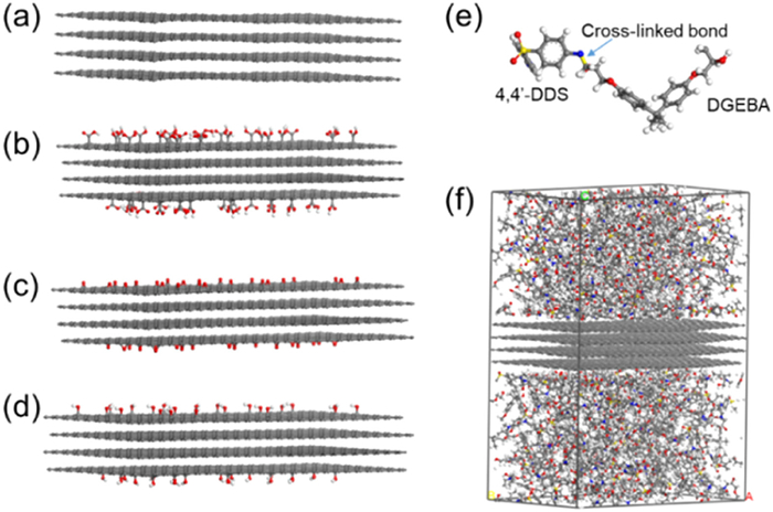
MD simulations were conducted employing the Material Studio and the Large-scale Atomic/Molecular Massively Parallel Simulator (LAMMPS) software. Graphite and graphite with different oxygen-containing functional group model are depicted in Figs. 1a–d, wherein the mole fraction of attracted functionalized groups approximated 5%, distributed randomly on the graphite surface, aligning with the functional degree observed in actual experiments [32–34]. Before assembling the composite model, it is necessary to establish crosslinking reaction between DGEBA and 4,4′-DDS for the resin, as illustrated in Fig. 1e. To achieve crosslinking of EP, the simulated systems encompassed twice as many DGEBA molecules as 4,4′-DDS molecules to maintain stoichiometric equilibrium, with a crosslinking conversion of 90% according to the experimental experience of the paper [35,36]. In this study, the composite model (Fig. 1f), encompassing approximately 15,800 atoms in periodic cells with lattice parameters set to 61 Å × 38 Å × 86 Å, was selected to explore the interplay among components, structure, and properties of the composite system, as well as the impact of functional groups on the formation of the interface between the resin and graphite.
Figure 1
Figure 1.
Simulation models of (a) pristine nature graphite and graphite functionalized with (b) carboxyl, (c) epoxy, and (d) hydroxyl. (e) The crosslinking structure of 4,4′-DDS curing agent and DGEBA molecule. (f) G/EP composite model. The balls with different colors represent different elements (white for H, grey for C, blue for N, red for O, and yellow for S).
The van der Waals and Coulomb interactions were calculated employing the "Atom-based" and "Ewald" methodologies. The cut-off distance for non-bonded interactions was set to 12.5 Å, with a buffer of 0.5 Å. The temperature was regulated using a Nosé-Hoover thermostat for the canonical ensemble (NVT) dynamics and a Berendsen thermostat for the constant-temperature, constant-pressure (NPT) dynamics. The pressure was maintained under control utilizing a Parrinello Rahman barostat.
For each model, geometric optimization was executed over 5000 iterations to attain energy convergence in the first place. Then, annealing simulations were carried out from 1000 K to 300 K to make the interface model molecule into an active state. MD simulations were then carried out for the interface model in the NVT ensemble for 500 ps and in the NPT ensemble for 500 ps at 1000 atm at 1000 K, 1 atm and 300 K, respectively, to dissipate excess energy, thus attaining the optimal state for subsequent simulations. All dynamic simulations were conducted using a time step of 1 fs.
The mechanical response of composites under uniaxial tension was investigated using non-equilibrium MD simulations. In these simulations, the composites were deformed at a constant strain rate of 1 × 10¹⁰ s−1 perpendicular to the composite interface, while atmospheric pressure was maintained in the other two transverse directions using a barostat.
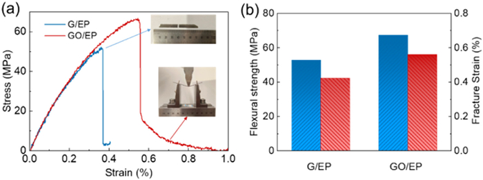
As depicted in Fig. 2, the flexural strength of the GO/EP composite reached 67.3 MPa, which was higher than that of the G/EP composite (52.7 MPa), implying that the surface oxidation of graphite remarkably bolstered the flexural strength of the composite bipolar plate by a noTable 27.7%. It was evident that the G/EP composite plate exhibited complete fracture when the stress reached the flexural strength, whereas the GO/EP composite plate only experienced a partial fracture, showing a bending mode. Impressively, the GO/EP composite plate showcased the ability to endure significant stress levels until the strain reached about 1%. This notable capability signified that the GO/EP composite plate could attain a more expansive strain state than the G/EP composite plate. Such a more strength and tough composites provide highly advantageous for fuel cells, as it ensured the maintenance of a relatively integral structure even when subjected to external pressures, thereby reducing the risks of safety incidents such as hydrogen leakage [37] resulting from plate fragmentation.
Figure 2
Figure 2.
(a) The stress-strain curve, (b) flexural strength and fracture strain of the composite samples.
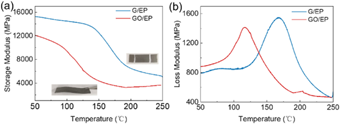
Fig. 3 illustrates the dynamic mechanical response of the composite samples. A noticeable distinction emerged when comparing the G/EP composite material with GO. The decreases in storage modulus for GO occurred more progressively. In this study, the temperature linked to the peak value of the loss modulus was designated as the glass transition temperature. Intriguingly, in contrast to the G/EP composite sample, the glass transition temperature of GO/EP exhibits a slight decrease, highlighting that the transition of moduli in the GO/EP system was characterized by a gradual change, leading to a reduction in stress concentration at the interface and an enhancement in stress transfer within the interface phase. Furthermore, a compelling observation came to light: As the temperature reached 250 ℃, distinct differences manifested between the G/EP composite sample and the GO/EP composite material. At this point, the G/EP composite sample distinctly exhibited signs of fracture, whereas the GO/EP composite material displayed a bending response devoid of pronounced fracture indications. This pivotal finding underscored the superior toughness of GO/EP over G/EP, a consistency that harmonized with the outcomes derived from the bending tests.
Figure 3
Figure 3.
Temperature dependence of (a) storage modulus and (b) loss modulus of the composite.
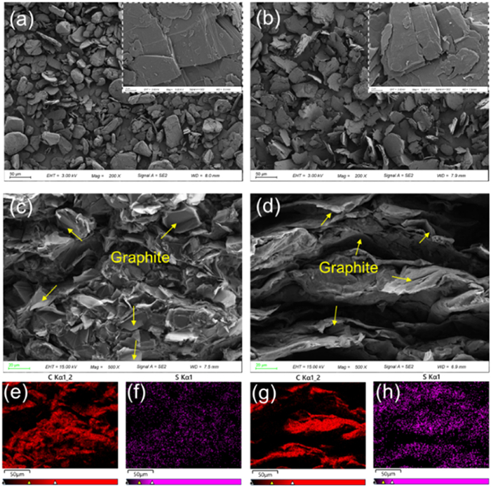
Concerning the chemical analysis of graphite, a comprehensive investigation was carried out in a prior publication [31]. Instead, our focus shifted to an analysis of material particle size (Figs. 4a and b) and cross-sectional morphology of the bipolar plate samples. Notably, the cross-section of the G/EP sample displayed a fragmented disposition, with distinct graphite layers visibly discernible (Fig. 4c). In contrast, the cross-section of the GO/EP sample revealed a distinct layered structure (Fig. 4d), and mapping analysis further confirmed the extensive resin coverage on its surface (Figs. 4e–h). These results underscored that the GO/EP sample exhibited superior and more stable interface bonding between the resin and graphite when compared to the G/EP sample.
Figure 4
Figure 4.
SEM images of (a) graphite and (b) graphite oxide. SEM images of the cross-sectional of (c) G/EP composite and (d) GO/EP composite. EDS mapping results of (e, f) G/EP composite and (g, h) GO/EP composite.
To enhance the comprehension of interface morphology and mechanical properties between oxidized graphite and resin, we computed the interface properties of graphite and resin with varying functional groups using Eq. S4 (Supporting information). The results demonstrated that the addition of functional groups (−1503 kcal/mol) to the graphite surface led to a decrease in the interface binding energy compared to that of G/EP (Fig. S3 in Supporting information). Significantly, the epoxy functional group (−1576 kcal/mol) and hydroxyl group (−1565 kcal/mol) emerged as particularly influential enhancers of the interface binding energy. However, the longer chain of the carboxyl group, consisting of four atoms, led to increased steric hindrance between carboxylated graphite and EP. Therefore, the interface binding energy for carboxylated graphite (−1500 kcal/mol) did not deviate significantly from that of G/EP.
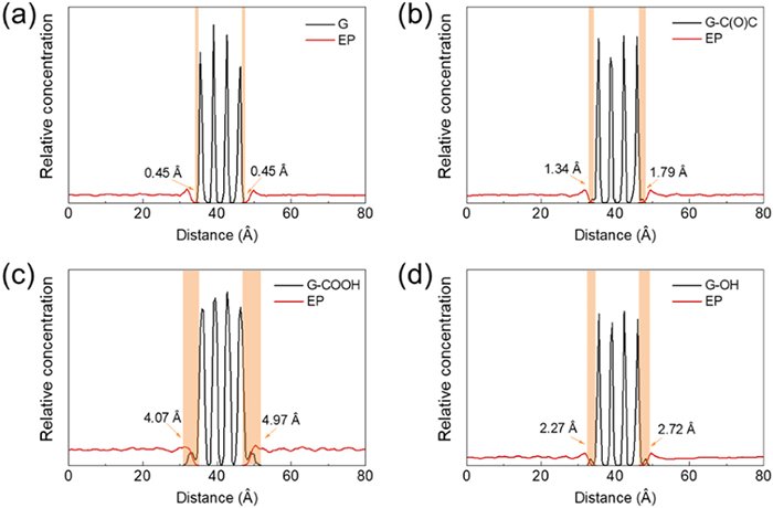
The interface thickness was determined by analyzing the relative concentrations of resin and graphite in the Z direction of the model (Fig. 5). The results uncovered that pure graphite possessed the thinnest interface thickness among all the composite models, measuring only 0.45 Å. In contrast, carboxyl-functionalized graphite exhibited a thicker interface with the resin (4.07 Å and 4.97 Å). This deformation of graphite is caused by uneven surface stress after modification of functional groups, with the functional groups themselves exerting an attractive force on the epoxy end groups of EP [31]. Therefore, a thicker interface could be formed between graphite oxide and EP. Taken together, these findings illustrated that the incorporation of functional groups improved the affinity between graphite and resin.
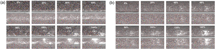
Fig. S2 (Supporting information) presents the stress-strain curves for uniaxial tensile deformation along various normal directions of the composite interface. The results highlighted those composite models containing functional groups demonstrated a lower tensile modulus than G/EP, which was in line with experimental observations. To broaden our knowledge on the yielding and post-yield processes in composite materials, the molecular processes involved in uniaxial deformation were analyzed. Snapshots of the composite material during parallel stretching along the interface direction are displayed in Fig. 6. Under 20% strain, the parallel scenario unveiled nanoscale gaps between graphite and resin, which progressively expanded during stretching. However, in composite models with functional groups, the voids primarily existed within the resin molecules (Fig. S4 in Supporting information). With continued deformation, these voids expanded and merged. The variations in failure mechanisms could be attributed to the adhesion between the polymer and graphene. While the van der Waals interactions between the polymer and graphene atoms remain consistent in both scenarios, the presence of functional groups amplifies the binding at the graphene-EP interface, leading to enhanced stability of the interface structure.
Figure 6
Figure 6.
The snapshots of the composite model (a) G/EP, (b) G-COOH/EP during uniaxial tensile.
In conclusion, this study delves into investigating the mechanical properties of composite materials fabricated utilizing graphite with surface oxidation. The research reveals that the composite bipolar plates prepared from graphite oxide exhibits superior mechanical strength and toughness compared to pristine nature graphite, while also exhibiting improved electrical conductivity. Microstructural analysis of GO/EP highlights relatively intact interface morphology even post-fracture. The outcomes from MD simulations further validate that functional groups bolster the interfacial strength between graphite and resin, and interface failure predominantly manifests within the resin. These findings provide insightful guidance for improving composites interfaces, enabling high load transfer efficiency, and opens up a potential path for developing strong and tough composite bipolar plates for fuel cells.
Declaration of competing interest
The authors declare that they have no known competing financial interests or personal relationships that could have appeared to influence the work reported in this paper.
Acknowledgment
The authors would like to acknowledge the financial supports from the National Key R&D Program of China (No. 2020YFB1505901).
Supplementary materials
Supplementary material associated with this article can be found, in the online version, at doi:10.1016/j.cclet.2023.109382.
[1]
Q. Kang, G. Zhang, Y. Liu, Z. Zhang, Battery Bimonthly 49 (2019) 346–349.
[2]
D. Feng, Y. Feng, L. Qiu, et al., Renew. Sust. Energ. Rev. 109 (2019) 578–605. doi: 10.1016/j.rser.2019.04.041
[3]
G. Zhang, Z. Qu, W.Q. Tao, et al., Chem. Rev. 123 (2022) 989–1039.
W. Ren, L. Xiong, G. Nie, et al., Environ. Sci. Technol. 54 (2019) 1267–1275.
[12]
B.K. Kakati, A. Ghosh, A. Verma, Proceedings of the Asme 9th International Conference on Fuel Cell Science, Engineering, and Technology 2011-2012, pp. 301–307.
[13]
B. Lv, Z. Shao, L. He, Y. Gou, S. Sun, Prog. Nat. Sci. 30 (2020) 876–881. doi: 10.1016/j.pnsc.2020.10.012
[14]
J. Rao, P. Zhang, S. He, et al., Sci. Sin. Technol. 47 (2017) 13–31. doi: 10.1360/N092015-00380
Figure 1
Simulation models of (a) pristine nature graphite and graphite functionalized with (b) carboxyl, (c) epoxy, and (d) hydroxyl. (e) The crosslinking structure of 4,4′-DDS curing agent and DGEBA molecule. (f) G/EP composite model. The balls with different colors represent different elements (white for H, grey for C, blue for N, red for O, and yellow for S).
Figure 4
SEM images of (a) graphite and (b) graphite oxide. SEM images of the cross-sectional of (c) G/EP composite and (d) GO/EP composite. EDS mapping results of (e, f) G/EP composite and (g, h) GO/EP composite.

 DownLoad:

 下载:
下载:


