Figure 1.
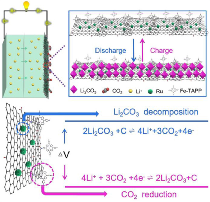
The schematic representation of Ru/Fe-TAPP@GO and their effect as cathode catalyst in Li-CO2 battery.
Three-in-one Fe-porphyrin based hybrid nanosheets for enhanced CO2 reduction and evolution kinetics in Li-CO2 battery
Shan Li , Jian-Hui Wang , Long-Zhang Dong , Yu Zhang , Xiao-Man Yao , Yifa Chen , Shun-Li Li , Ya-Qian Lan

Li-CO2 battery, arisen from the similar configuration of Li-O2 battery, has attracted more and more attention in recent years [1-3]. It is an efficient CO2 fixation and energy storage technique based on the CO2 reduction and evolution reactions, in which CO2 can be applied as the energy carrier [4,5]. Typically, the possible discharge/charge reactions have been reported as: 4Li+ + 3CO2 + 4e− → 2Li2CO3 + C [6,7], achieving much higher theoretical energy density (1876 Wh/kg) than traditional lithium-ion batteries (≈ 265 Wh/kg) [8]. Nonetheless, the sluggish CO2 reduction reaction (CRR) or CO2 evolution reaction (CER) kinetics have restricted the development of Li-CO2 battery and generally resulted in unsatisfied performance like high overpotential, poor reversibility or low cycling stability, etc. To conquer it, one of the key solutions is to design efficient cathode catalysts that aim to simultaneously conquer the CRR/CER reaction barriers to achieve fast kinetics, low overpotential and high cycling stability, etc. [9,10]. Therefore, multi-requirements related to the bottlenecks of Li-CO2 battery are needed, and thus enhancing the challenging in cathode catalyst design to achieve high battery performance [11-13].
The basic requirement of cathode catalysts lies in the multi-functionality like high electro-redox property for both CER and CRR processes, high stability or essential conductivity, etc. [14]. To date, some pioneering cathode catalysts have been designed, including carbon materials [15-17], noble metals [18-21], transition metals or their oxides/carbides [22-25], porous crystalline materials [26-29], etc. For example, some noble metal (e.g., Ru or Ir) based nanomaterials have showed interesting performances in Li-CO2 battery especially for their high electrocatalytic ability for Li2CO3 decomposition in CER process [18-20,30]. However, works reported to date were generally far from practical applications and most of the reported cathode catalysts were unmet for the multi-requirements (e.g., high conductivity, simultaneously demanded CRR and CER catalytic ability, long-term stability) of high-performance Li-CO2 battery by themselves. It would be hard to meet most of the requirements by single-component cathode catalyst, and two- or multi-component ones are more essential. Thus, multi-component hybrid materials especially that can combine the functionality of various integrated-components have arisen to be promising candidates as cathode catalysts [31].
Conjugated macrocyclic compounds with single-metal sites (e.g., metallo-porphyrins and metallo-phthalocyanines) show promising prospects in various applications, such as catalysis, solar battery, biochemical applications and energy storage [32,33]. They have proven to be beneficial for the CO2 activation process in photo-/electro-catalytic CO2 reduction reaction and Li-CO2 battery [29,34-37]. Inspired by this, we intend to assemble Fe-porphyrin (denoted as Fe-TAPP), noble metals and GO as hybrid nanosheets (NSs) to produce powerful cathode catalysts [38]. A well-known conjugated macrocyclic compound, Fe-TAPP was rationally selected to be integrated with Ru nanoparticles (NPs) onto the GO NSs. The corresponding considerations are listed as follows: (1) Fe-TAPP molecule with Fe-N4 sites and highly conjugated structure might be favorable for the CRR process and provide strong π-π interaction with GO NSs; (2) Ru NPs is a common and efficient Li-CO2 catalyst that can promote the CER process to some extent; (3) GO NSs with large surface area and tremendous functional groups would serve as desired substrate for the dispersion of Fe-TAPP and Ru NPs, providing large surface area, fast electron transfer ability, high electric conductivity and desired carriers for discharge products [17,39,40] and (4) the combination of them would generate a kind of multi-functional hybrid cathode catalyst with synergistically promoted CRR and CER kinetics for Li-CO2 battery. From the above we deduce that such a kind of hybrid catalyst will probably be promising candidate to conquer the drawbacks of Li-CO2 battery, while the assembly of this type of hybrid material is still rare as far as we know.
As a proof-of-concept, we have successfully synthesized a kind of Ru/Fe-TAPP@GO hybrid NSs through a one-pot reflux method (Fig. 1). The obtained Ru/Fe-TAPP@GO with integrated multi-components offers characteristics of ultrathin thickness (~4 nm), remarkable CO2 electro-redox property, uniformly dispersed morphology, and high electric conductivity and so on. As expected, these features endow Ru/Fe-TAPP@GO with ultra-low overpotential (0.82 V) and fully reversible discharge/charge property with a high specific-capacity of 39,000 mAh/g within 2.0–4.5 V at 100 mA/g, which is superior to Ru@GO and Fe-TAPP@GO. The achieved performance was presented as one of the best cathode catalysts reported to date. These findings offer a deep insight into the synergistically catalytic effects of hybrid materials on battery performance, as well as a promising strategy for developing powerful cathode catalysts for Li-CO2 battery.
Ru/Fe-TAPP@GO hybrid NSs was synthesized through a one-pot reflux method using Fe-TAPP, GO and RuCl3·xH2O as the precursors (detail see Methods in Supporting information). To characterize it, we have performed a series of characterizations to evaluate the basic properties of hybrid NSs. In Fig. 2a, PXRD test of Ru/Fe-TAPP@GO showed main peaks at 38.4°, 42.1° and 44.0°, which could be ascribed to (100), (002) and (101) crystal lattices of Ru (PDF#65–1863). Besides, the broad peak among the range from 20° to 30° can be attributed to GO when compared with the spectrum of GO. The characteristic peaks of Ru also can be seen in the PXRD pattern of Ru@GO (Fig. S1 in Supporting information). Moreover, XPS tests were used to determine the elemental composition and surface electronic state of Ru/Fe-TAPP@GO. Fig. 2b showed the characteristic peaks of Ru 3p3/2 (462.6 eV) and Ru 3p1/2 (484.8 eV) of Ru, implying Ru(Ⅲ) was reduced to Ru after reaction [41]. Meanwhile, the existence of characteristic peaks for Fe 2p3/2 (711.5 eV) and Fe 2p1/2 (724.8 eV) indicates the trivalent valance of Fe in the Fe-TAPP [42]. The both existence of Ru and Fe (Ⅲ) also confirms the successful integration of Ru and Fe-TAPP in Ru/Fe-TAPP@GO. As comparison, the Ru and Fe(Ⅲ) with similar characteristic peaks were also detected in Ru@GO and Fe-TAPP@GO, respectively (Figs. S2 and S3 in Supporting information).
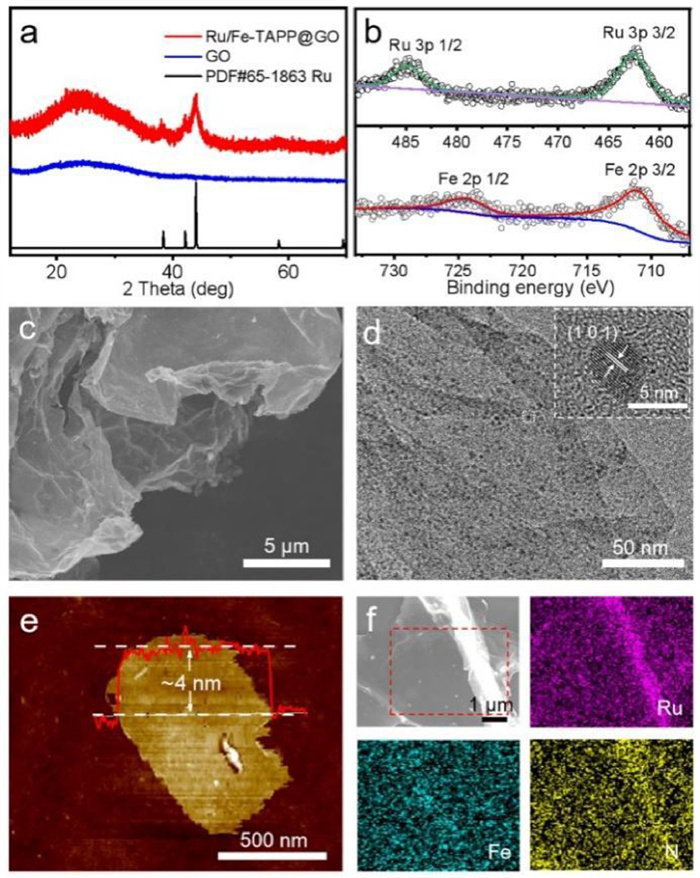
Fig. S4 (Supporting information) showed that the peaks at 1224 cm−1, 1731 cm−1, and 3420 cm−1 were corresponded to epoxy, carbonyl and hydroxyl groups of GO in FTIR spectra, respectively [43]. The FTIR spectrum of Ru/Fe-TAPP@GO showed that the characteristic peaks at 1731 cm−1 (C=O) of GO as well as the peaks at 1607 cm−1 (-NH2) of Fe-TAPP were weaken, implying that Fe-TAPP might interact with GO through the as-reported reaction of -NH2 and epoxy/carbonyl groups [43]. In contrast, the characteristic peak observed at 1731 cm−1 (C=O) of GO in Ru@GO still remained almost unchanged (Fig. S4). In addition, Fig. S5 (Supporting information) showed the peaks for D band and G band (i.e., 1354 and 1606 cm−1) in GO were slightly shifted to 1346 and 1589 cm−1 in the Raman spectra, further supporting the possible interaction generated between Fe-TAPP and GO [44,45].
Moreover, SEM and TEM tests have been applied to investigate the relative morphology. Fig. 2c showed that the obtained Ru/Fe-TAPP@GO was in nanosheet morphology with smooth surface in the SEM image. In the TEM test (Fig. 2d), Ru NPs were detected and uniformly dispersed on the GO NSs with average diameter of about 3.66 ± 0.61 nm (Fig. S6 in Supporting information). In the HR-TEM test, visible crystal lattice of ~2.1 Å was detected and ascribed to (101) lattice plane of Ru. Besides, Fig. 2f showed the elemental mapping images and the results revealed that Ru, Fe and N were uniformly distributed in the NSs, supporting the evenly dispersion of Fe-TAPP and Ru. To detect the thickness of NSs, the atomic force microscopy (AFM) tests were performed. Specifically, in Fig. 2e, the thickness of Ru/Fe-TAPP@GO hybrid NSs was estimated to be ~4 nm over a large piece of NSs (width, ~1 µm). The hybrid NSs was synthesized using GO as the precursor, which could provide a kind of porous substrate that was much beneficial for the mass transfer. Therefore, we have successfully synthesized a kind of Ru/Fe-TAPP@GO hybrid NSs with uniformly dispersed Ru NPs and Fe-TAPP onto GO NSs, which may be a promising candidate for improving the performance of Li-CO2 batteries.
Fig. 3a showed that the initial battery performance of Ru/Fe-TAPP@GO as the cathode catalysts was evaluated and it possessed the 1st discharged end potential of 3.08 V and the 1st charged end potential of 3.90 V. Noteworthy, the overpotential for the first cycle was only 0.82 V, which was presented to be one of the best cathode catalysts as far as we know (Table S1 in Supporting information) [2]. Moreover, it displayed that Ru/Fe-TAPP@GO only had slight potential plateau change in cycles, indicating the high activity and stability in battery tests. With the assembly of three components in the hybrid NSs, the achieved three-in-one system would play synergistic effect on the Li-CO2 battery performance. Thus, we further investigated the possible influence of component content, and catalysts containing different proportions of Ru (i.e., Ru/Fe-TAPP@GO-1/2Ru and Ru/Fe-TAPP@GO-3/2Ru) were prepared and tested (detail see Methods). The results showed that when Ru content was relatively low (i.e., Ru/Fe-TAPP@GO-1/2Ru), the overpotential for the first cycle was 1.08 V and it increased sharply in short time (Fig. S7 in Supporting information). Besides, when the Ru content was higher (i.e., Ru/Fe-TAPP@GO-3/2Ru), the discharge voltage of the battery decreased slightly, and the performance was also poorer than that of Ru/Fe-TAPP@GO (Figs. S8 and S9 in Supporting information). There seems to exist a balance between Ru and Fe-TAPP, and only the sample with appropriate Ru content would possess the best synergistic effect. Moreover, to determine the vital role of different components in Li-CO2 battery, GO, Ru@GO and Fe-TAPP@GO were also tested as the contrast cathode catalysts (Figs. S10 and S11 in Supporting information). In sharp contrast, the 1st discharge/charge end voltage platforms of GO were 2.62 V and 4.60 V, respectively, and the battery cannot be fully charged back (Fig. S12 in Supporting information). In Fig. 3b, the 1st discharge and charge end voltage platforms of Fe-TAPP@GO were 2.96 V and 4.60 V, respectively, which confirmed that Fe-TAPP was favorable for the CRR process yet was still short in CER process when compared with that of Ru/Fe-TAPP@GO. With the absence of Fe-TAPP, the 1st discharge/charge end voltage platforms of Ru@GO were 2.77 V and 4.04 V, respectively, which certified that Ru was beneficial for the CER process.
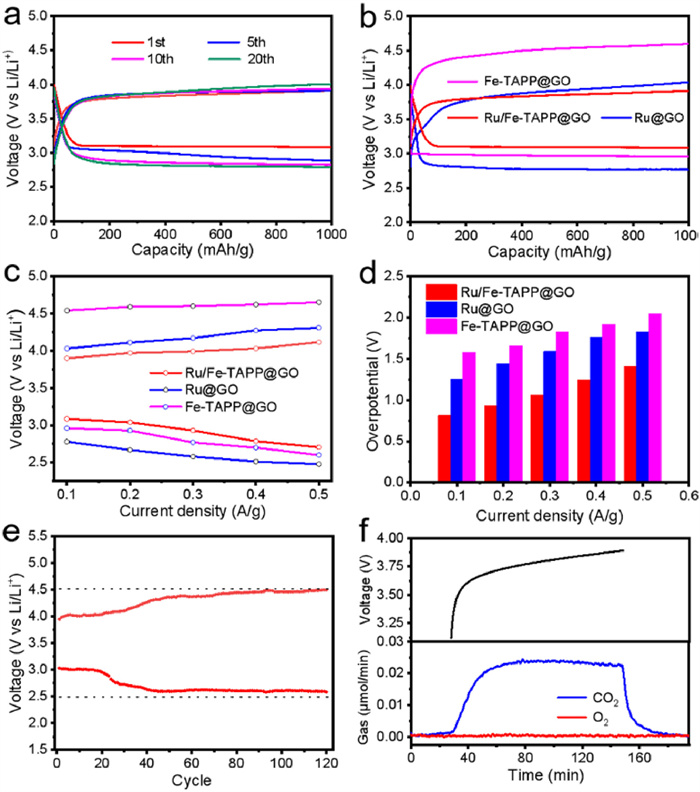
Furthermore, EIS analysis was used to measure the internal resistance of Ru/Fe-TAPP@GO hybrid NSs based Li-CO2 cells, which showed that Ru/Fe-TAPP@GO hybrid NSs had lower EIS value than that of Ru@GO and Fe-TAPP@GO (Fig. S13 in Supporting information). This result indicated that the integration of Fe-TAPP and Ru NPs would possess synergistic effect on the charge or electron conducting. The electrochemical performance of Ru/Fe-TAPP@GO hybrid NSs was also investigated by discharging/charging the Li-CO2 cells at different current densities with a limited capacity of 1000 mAh/g. Fig. 3c displayed the first flat discharge and charge plateau for the Li-CO2 cell at different current densities. Ru@GO and Fe-TAPP@GO were selected as the contrast samples to be compared with Ru/Fe-TAPP@GO hybrid NSs at various current density. Specifically, the discharge voltages of Ru/Fe-TAPP@GO hybrid NSs were 3.08, 3.04, 2.93, 2.79 and 2.71 V at current densities of 0.1, 0.2, 0.3, 0.4 and 0.5 A/g, which were significantly higher than that of Ru@GO and Fe-TAPP@GO. The charging voltage Ru/Fe-TAPP@GO hybrid NSs was also much better than that of Ru@GO. As the synergistic effect and high conductivity of hybrid materials can promote the CO2 reduction and evolution reactions in Li-CO2 cells, the discharge/charge curves of Li-CO2 cells with Ru/Fe-TAPP@GO hybrid NSs as the cathode catalyst showed lower overpotential when compared with that of Ru@GO cell (Fig. 3d). Besides, the cycling performance has been evaluated with a large current density of 300 mA/g. Fig. 3e showed that the Li-CO2 battery with Ru/Fe-TAPP@GO hybrid NSs cathode can cycle 120 times in the range of 2.5 V to 4.5 V. Under the same current density, Ru@GO and Fe-TAPP@GO were poorer than that of Ru/Fe-TAPP@GO in the cycling tests (Fig. S14 in Supporting information).
At the same time, the redox current existed only when the atmosphere of cyclic voltammetry (CV) test was CO2, proving that CO2 was the active substance in the test (Fig. S15 in Supporting information). To further verify the complete reversibility of Ru/Fe-TAPP@GO hybrid NSs Li-CO2 battery, gas evolution from Ru/Fe-TAPP@GO hybrid NSs based Li-CO2 battery during charge was monitored using in-situ differential electrochemical mass spectrometry (DEMS) test. Fig. 3f presented that the battery only released CO2 during the charging process and no detection of O2. According to DEMS results, the charge mass ratio in the charging process was determined to be 4.19 e−/3CO2, implying that it basically matched with the reversible reaction of 4Li+ + 3CO2 + 4e− → 2Li2CO3 + C. These results indicated that the synergistic effect in Ru/Fe-TAPP@GO NSs catalyst could effectively increase the battery performance.
Fig. 4a presented the deep discharge-charge profiles of the Li-CO2 batteries at 100 mA/g from 2.0 V to 5.0 V vs. Li/Li+. It was worth noting that the battery of Ru/Fe-TAPP@GO hybrid NSs was reversible in the deep discharge state and could be fully recharged back after the deep discharge process. GO had a large specific surface area to disperse discharge products and high conductivity to enable fast electron transport, which will provide abundant diffusion channels for Li ions and CO2 when applied as substrate for Ru and Fe-TAPP [39,46]. As expect, the specific capacity of Ru/Fe-TAPP@GO hybrid NSs was as high as 39,000 mAh/g, which was superior to Fe-TAPP@GO (16,911 mAh/g) and Ru@GO (30,565 mAh/g). Moreover, the high starting discharge voltage of Ru/Fe-TAPP@GO hybrid NSs (3.08 V) and Fe-TAPP@GO (3.00 V) also implied that the function of Fe-TAPP with Fe-N4 sites could effectively promote the CRR process.
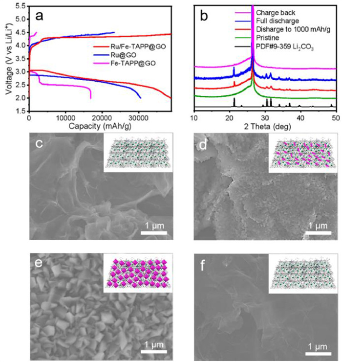
Generally, the poor stability of Li-CO2 battery was mainly due to the incomplete decomposition of Li2CO3 in the charging process, which leaded to the blockage of diffusion channel, passivation of cathode surface and degradation of battery performance. A functional Li-CO2 cathode catalyst must be able to efficient limit the deposition of Li2CO3 and catalyze the decomposition of Li2CO3 [47]. To investigate it, the discharge products of Ru/Fe-TAPP@GO hybrid NSs at different stages in a discharge/charge cycle at 100 mA/g with a fixed capacity of 1000 mAh/g (voltage range: 2.0–4.5 V vs. Li/Li+) were characterized. Four stages have been selected as desired states including pristine state, discharge to 1000 mAh/g, full discharge and recharge back during discharge/charge cycle and PXRD tests were applied to detect the phase change. When the battery discharged to 1000 mAh/g, new peaks belonging to Li2CO3 crystal (PDF#9–359) appeared when compared with the original state, indicating that crystal Li2CO3 was the main discharge product of the battery. After reaching the full discharge stage at 1000 mAh/g, the peak strength of Li2CO3 increased. When the battery was fully charged back, the peak of Li2CO3 completely disappeared, indicating the battery system enabled completely reversible discharge/charge process (Fig. 4b).
To further verify the results detected in the PXRD tests, SEM tests have also been conducted to trace the formation and decomposition morphology of Li2CO3 in the Ru/Fe-TAPP@GO cathode (Figs. 4c and d). Compared with the original stage, Li2CO3 NPs with an average size of ~120 nm were formed on the surface of the Ru/Fe-TAPP@GO hybrid NSs base cathode at the stage of discharge to 1000 mAh/g. Fig. 4e showed that Li2CO3 NPs displayed a kind of bulky nanocrystal (~370 nm) when reaching the full discharge stage and covered most of the surface area. After fully charging back, all the Li2CO3 NPs disappeared in the SEM image, proving that the battery system was completely reversible (Fig. 4f). In addition, we have conducted the attenuated total reflection Fourier transform infrared (ATR-FTIR) and Raman test to trace the dynamic evolution of the structures and compositions of the electrode materials during the discharge and charge processes. In Fig. S16 (Supporting information), the peak corresponding to δ(O-C=O) of Li2CO3 at 860 cm−1 in ATR-FTIR test continuously increases with the process of discharge, and further gradually disappears along the charge process, proving the reversibility of formation and decomposition of Li2CO3 during these processes [30,39]. Moreover, the peak of ~1005 cm−1 belonging to Li2CO3 can be observed after discharge in Raman spectra, and it almost disappears after charging back, indicating the reversible charge and discharge process of the battery (Fig. S17 in Supporting information) [41]. In contrast, the cathodes based on Ru@GO and Fe-TAPP@GO could not restore to their original states when they were charged back (Figs. S18 and S19 in Supporting information). At the same time, the XPS tests were used to explore the stability of catalyst, and the XPS spectra suggested they were almost the same for the pristine and charge back states (Fig. S20 in Supporting information)
In summary, we have successfully synthesized a kind of Ru/Fe-TAPP@GO hybrid NSs through a one-pot reflux method. The obtained Ru/Fe-TAPP@GO with integrated multi-components offers characteristics of high electro-redox property, uniformly dispersed morphology, and high electrical conductivity. These features endowed Ru/Fe-TAPP@GO with ultra-low overpotential (0.82 V) and fully reversible discharge/charge property with a high specific-capacity of 39,000 mAh/g within 2.0–4.5 V at 100 mA/g, which were much superior to Ru@GO and Fe-TAPP@GO. The achieved performance was presented as one of the best cathode catalysts reported to date. Besides, the discharge/charge process were intensively investigated with sufficient characterizations like PXRD, SEM and DEMS tests, revealing the vital role of Ru/Fe-TAPP@GO in the reversible battery cycles. The synergistically enhanced activity originated from the integrated hybrid NSs may provide a new insight for designing efficient cathode catalysts for Li-CO2 batteries.
The authors report no declarations of interest.
This work was financially supported by the National Natural Science Foundation of China (NSFC, Nos. 21871141, 21871142, 21901122, 22071109, 22105080, 22171139 and 92061101), the Excellent Youth Foundation of Jiangsu Natural Science Foundation (No. BK20211593), Priority Academic Program Development of Jiangsu Higher Education Institutions and the Foundation of Jiangsu Collaborative Innovation Center of Biomedical Functional Materials.
Supplementary material associated with this article can be found, in the online version, at doi:
Z. Xie, X. Zhang, Z. Zhang, Z. Zhou, Adv. Mater. 29 (2017) 1605891. doi: 10.1002/adma.201605891
Y. Jiao, J. Qin, H.M.K. Sari, et al., Energy Stor. Mater. 34 (2021) 148-170.
Q.Q. Hao, Z. Zhang, Y. Mao, K.X. Wang, ChemNanoMat 8 (2022) e202100381.
X. Mu, H. Pan, P. He, H. Zhou, Adv. Mater. 32 (2020) 1903790.
J. Xie, Z. Zhou, Y. Wang, Adv. Funct. Mater. 30 (2020) 1908285. doi: 10.1002/adfm.201908285
X. Li, S. Yang, N. Feng, P. He, H. Zhou, Chin. J. Catal. 37 (2016) 1016-1024. doi: 10.1016/S1872-2067(15)61125-1
S. Yang, P. He, H. Zhou, Energy Environ. Sci. 9 (2016) 1650-1654. doi: 10.1039/C6EE00004E
Z. Zhang, W.L. Bai, K.X. Wang, J.S. Chen, Energy Environ. Sci. 13 (2020) 4717-4737. doi: 10.1039/d0ee03058a
J. Li, A. Dai, K. Amine, J. Lu, Small 17 (2021) 2007760. doi: 10.1002/smll.202007760
Z. Zhao, E. Wang, J. Wang, C. Liu, Z. Peng, J. Mater. Chem. A 9 (2021) 3290-3296. doi: 10.1039/d0ta11281j
A. Hu, C. Shu, C. Xu, et al., J. Mater. Chem. A 7 (2019) 21605-21633. doi: 10.1039/c9ta06506g
B. Liu, Y. Sun, L. Liu, et al., Energy Environ. Sci. 12 (2019) 887-922. doi: 10.1039/c8ee03417f
X. Sun, Z. Hou, P. He, H. Zhou, Energy Fuels 35 (2021) 9165-9186. doi: 10.1021/acs.energyfuels.1c00635
C. Jiang, Y. Zhang, M. Zhang, et al., Cell Rep. Phys. Sci. 2 (2021) 100392. doi: 10.1016/j.xcrp.2021.100392
Z. Zhang, Q. Zhang, Y. Chen, et al., Angew. Chem. Int. Ed. 54 (2015) 6550-6553. doi: 10.1002/anie.201501214
X. Li, J. Zhou, J. Zhang, et al., Adv. Mater. 31 (2019) 1903852. doi: 10.1002/adma.201903852
J. Zhang, F. Wang, G. Qi, et al., Adv. Funct. Mater. 31 (2021) 2101423. doi: 10.1002/adfm.202101423
Y. Qiao, J. Yi, S. Wu, et al., Joule 1 (2017) 359-370. doi: 10.1016/j.joule.2017.07.001
Y. Xing, Y. Yang, D. Li, et al., Adv. Mater. 30 (2018) 1803124. doi: 10.1002/adma.201803124
Y. Qiao, S. Xu, Y. Liu, et al., Energy Environ. Sci. 12 (2019) 1100-1107. doi: 10.1039/c8ee03506g
C. Wang, Q. Zhang, X. Zhang, et al., Small 14 (2018) 1800641. doi: 10.1002/smll.201800641
W. Ma, S. Lu, X. Lei, X. Liu, Y. Ding, J. Mater. Chem. A 6 (2018) 20829-20835. doi: 10.1039/c8ta06143b
Q. Liu, Z. Hu, L. Li, et al., ACS Appl. Mater. Interfaces 13 (2021) 16585-16593. doi: 10.1021/acsami.1c03229
Y. Hou, J. Wang, L. Liu, et al., Adv. Funct. Mater. 27 (2017) 1700564. doi: 10.1002/adfm.201700564
J. Zhou, X. Li, C. Yang, et al., Adv. Mater. 31 (2019) 1804439. doi: 10.1002/adma.201804439
S. Li, Y. Dong, J. Zhou, et al., Energy Environ. Sci. 11 (2018) 1318-1325. doi: 10.1039/c8ee00415c
L.Z. Dong, Y. Zhang, Y.F. Lu, et al., Chem. Commun. 57 (2021) 8937-8940. doi: 10.1039/d1cc03431f
Y. Zhang, R.L. Zhong, M. Lu, et al., ACS Cent. Sci. 7 (2021) 175-182. doi: 10.1021/acscentsci.0c01390
S. Huang, D. Chen, C. Meng, et al., Small 15 (2019) 1904830. doi: 10.1002/smll.201904830
Z. Zhang, W.L. Bai, Z.P. Cai, et al., Angew. Chem. Int. Ed. 60 (2021) 16404-16408. doi: 10.1002/anie.202105892
Z. Wang, F. Liu, X. Zeng, et al., Ionics (Kiel) 27 (2021) 2785-2802. doi: 10.1007/s11581-021-04009-w
R.J. Lim, M. Xie, M.A. Sk, et al., Catal. Today 233 (2014) 169-180. doi: 10.1016/j.cattod.2013.11.037
M. Wang, K. Torbensen, D. Salvatore, et al., Nat. Commun. 10 (2019) 3602. doi: 10.1038/s41467-019-11542-w
Y.R. Wang, Q. Huang, C.T. He, et al., Nat. Commun. 9 (2018) 4466. doi: 10.1038/s41467-018-06938-z
J. Li, H. Zhao, H. Qi, X. Sun, et al., Adv. Funct. Mater. 29 (2019) 1806863. doi: 10.1002/adfm.201806863
J. Chen, K. Zou, P. Ding, et al., Adv. Mater. 31 (2019) 1805484. doi: 10.1002/adma.201805484
Y. Xu, C. Jiang, H. Gong, et al., Nano Res. 15 (2022) 4100-4107. https://doi.org/10.1007/s12274-021-4052-1 doi: 10.1007/s12274-021-4052-1
Z. Zhang, C. Yang, S. Wu, et al., Adv. Energy Mater. 9 (2019) 1802805. doi: 10.1002/aenm.201802805
L. Qie, Y. Lin, J.W. Connell, J. Xu, L. Dai, Angew. Chem. Int. Ed. 56 (2017) 6970-6974. doi: 10.1002/anie.201701826
Z. Zhang, X.G. Wang, X. Zhang, et al., Adv. Sci. 5 (2018) 1700567. doi: 10.1002/advs.201700567
J.H. Wang, Y. Zhang, M. Liu, et al., Cell Rep. Phys. Sci. 2 (2021) 100583. doi: 10.1016/j.xcrp.2021.100583
G. Faubert, R. Côté, J.P. Dodelet, M. Lefèvre, P. Bertrand, Electrochim. Acta 44 (1999) 2589-2603. doi: 10.1016/S0013-4686(98)00382-X
J. Fu, P. Zong, L. Chen, et al., ChemNanoMat 2 (2016) 830-839. doi: 10.1002/cnma.201600131
U. Saha, R. Jaiswal, T.H. Goswami, Electrochim. Acta 196 (2016) 386-404. doi: 10.1016/j.electacta.2016.02.203
J.N. Chang, M. Zhang, G.K. Gao, et al., Energy Fuels 34 (2020) 16968-16977. doi: 10.1021/acs.energyfuels.0c03482
B. Chen, D. Wang, B. Zhang, et al., ACS Nano 15 (2021) 9841-9850. doi: 10.1021/acsnano.1c00756
X. Li, H. Wang, Z. Chen, et al., Adv. Mater. 31 (2019) 1905879. doi: 10.1002/adma.201905879

Figure 1 The schematic representation of Ru/Fe-TAPP@GO and their effect as cathode catalyst in Li-CO2 battery.

Figure 2 Characterization of Ru/Fe-TAPP@GO hybrid NSs. (a) PXRD patterns of Ru/Fe-TAPP@GO and GO. (b) XPS analyses of Fe and Ru for Ru/Fe-TAPP@GO. (c) SEM image of Ru/Fe-TAPP@GO. (d) TEM images of Ru/Fe-TAPP@GO. (e) AFM images of Ru/Fe-TAPP@GO. (f) Elemental mapping images of Ru/Fe-TAPP@GO.

Figure 3 The electrochemical performance of Li-CO2 battery with Ru/Fe-TAPP@GO, Ru@GO and Fe-TAPP@GO as the cathode catalysts. (a) Charging/discharging curves of Ru/Fe-TAPP@GO with the limited capacity of 1000 mAh/g at 100 mA/g. (b) The discharge/charge cycling curves of 1st cycle of Ru/Fe-TAPP@GO, Ru@GO and Fe-TAPP@GO with a limited capacity of 1000 mAh/g at 100 mA/g. (c) The discharge/charge potential of 1st cycle of different cathode catalysts with a limited capacity of 1000 mAh/g at various current densities. (d) Overpotentials of different cathode catalysts under current densities of 100 mA/g, 200 mA/g, 300 mA/g, 400 mA/g and 500 mA/g. (e) Long-term cycling curves of Ru/Fe-TAPP@GO cathode catalyst at 300 mA/g. (f) DEMS test during charging of the Li-CO2 battery with Ru/Fe-TAPP@GO cathode catalyst.

Figure 4 Products characterizations of battery reactions. (a) Deep discharge-recharge curves of Ru/Fe-TAPP@GO, Ru@GO and Fe-TAPP@GO cathodes with a limited voltage range of 2.0–4.5 V vs. Li/Li+ at 100 mA/g. (b) PXRD patterns of Ru/Fe-TAPP@GO based electrode at different stages. (c) SEM image of Ru/Fe-TAPP@GO based electrode. (d) SEM image of discharge 1000 mAh/g at 100 mA/g. (e) SEM image of full discharge. (f) SEM image of charge back.

 扫一扫看文章

扫一扫关注我们
 DownLoad:
 下载:
下载: