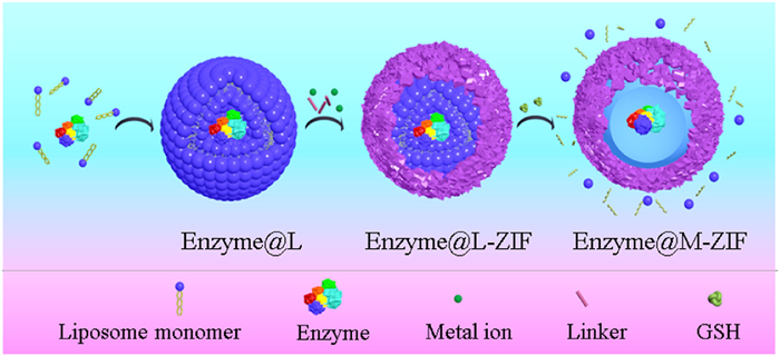
Figure 1.
Schematic representation of the in situ encapsulation of enzymes within M-ZIF via biodegradable L as sacrificial template.

Enzymes are natural catalysts produced by living cells. They have high specificity and catalytic efficiency for their substrates [1–5], which are key factors in the continuous development of biotechnology applications of enzymes [6–10]. However, the limitations of enzymes, such as low thermal stability, narrow optimal pH range, as well as low tolerance for most organic solvents and many metal ions, have greatly hindered their storage and application [11–13]. Additionally, enzymes are contaminants of the desired product, leading to inevitable purification and separation steps [14–16]. The immobilization of enzymes is one of the key strategies to improve the stability, reusability and continuous production capacity of enzymes, thereby improving their practical performance [17–24].
Metal-organic frameworks (MOFs) are porous materials with wide application prospects [25–27]. The excellent properties of MOFs-such as their high specific surface area, pore volume and ease of pore size adjustment-making them a desirable support matrix for enzyme immobilization [28–33]. However, despite these advantages, most MOFs-based enzyme reactors still face significant challenges. For example, traditional immobilization methods (e.g., adsorption, pore embedding) often result in low loading capacity, high leaching and the possibility of degradation in enzyme activity due to weak interactions or pore size mismatches between the enzyme and host material [34–38]. The co-precipitation strategy can overcome the shortcomings of the traditional incorporation methods. Nevertheless, embedding enzyme in tightly-packed host materials usually results in a lack of conformational freedom, which may greatly affect enzyme-substrate molecular recognition and the catalytic efficiency of enzymes [39–42]. In tight and narrow MOF channels, the mass transfer of substrates and products may also be a limiting factor. Large mass transfer resistance and a long mass transfer distance significantly reduce the activity of immobilized enzymes [43,44]. Therefore, there is an urgent need to explore new platforms to overcome these problems for optimal enzyme performance in confined spaces.
Herein, redox stimuli-responsive liposome (L) [45–47] was created as a sacrificial template for the fabrication of a "microporous MOF core-shell structure" for the encapsulation of natural enzymes. Zeolitic imidazolate frameworks (ZIFs) were selected to immobilize enzymes due to their advantages of synthesis temperature and aqueous solution [48,49]. ZIFs provided the shell for wrapping the enzymes to construct enzyme@ZIFs. Degradable L for the in situ encapsulation of enzymes to form enzyme@L was explored and served as a sacrificial template for the growth of the enzyme@L-ZIF capsule structure. The L was degraded via the redox reaction between glutathione (GSH) and the disulphide bond releasing the enzymes to form the core-shell structured microporous enzyme@ZIF (enzyme@M-ZIF). The spacious microenvironment in the resultant enzyme@M-ZIF promoted the mass transfer of substrates and products while maintaining the conformational freedom of the enzymes, which was essential for boosting the catalytic activity or synergistic interaction of different enzymes for cascade reactions. This provides a new approach to overcome the limitations of enzyme immobilization in porous supports.
To construct a large-cavity enzyme@MOF capsule structure, it was first necessary to select a template that was suitable for embedding enzymes and would not affect the biological macromolecules during the template removal. The L has bilayer structures that form spontaneously in water and their structures are similar to that of biological cells [50]. L is biocompatibile and can encapsulate and release molecules, enabling the targeting or efficient delivery of biomolecules. Thereby the L is a promising candidate to construct large-cavity MOF templates for the efficient immobilization of biomacromolecules.
To facilitate the easy removal of L without affecting the encapsulated enzymes, disulphide bonds with redox stimulus responsiveness were introduced into the L monomers during their synthesis. The L synthetic process is shown in Fig. S1 (Supporting information). Three L monomers (L1, L2, L3) were synthesized with the dodecyl chain as the hydrophobic terminal and N-(3-aminopropyl) diethanolamine, 1-(2-aminoethyl) pyrrolidine, or N-(3-aminopropyl) morpholine, as the hydrophilic end. The intermediates in the synthesis process and 1H nuclear magnetic resonance (1H NMR) spectra of the products are provided in Figs. S2-S7 (Supporting information), indicating the successful synthesis of the three kinds of L. Scanning electron microscope (SEM) was used to demonstrate the self-assembly effect of the prepared L in aqueous solution. As shown in Fig. S8 (Supporting information), the L-nanoparticles were uniformly distributed nanospheres in aqueous solution with a size of 300–400 nm. To explore the stimulation response characteristics of the prepared L, an L-nanoparticle suspension (1.0 mg/mL) was prepared and GSH (5.0 mmol/L) was added as the reducing agent to degrade the self-assembled L. When GSH solution was added to the suspension of L-nanoparticles, the opalescent opaque solution became instantaneously clear (Fig. S9 in Supporting information), this indicated that GSH successfully degraded the L-nanoparticles, and that they had desirable redox stimuli-response characteristics.
Enzymes were then encapsulated in degradable L-nanoparticles, which acted as the templates to fabricate the enzyme@L-ZIF with double-layer core-shell structures. Finally, through the stimulation response of GSH to disulphide bonds in the L, the degraded L-fragments were removed, forming a capsule junction with large-cavity enzyme@ZIFs-8 (Fig. 1).
First, using this strategy, L1 was designed to synthesize the M-ZIF structure for enzymes before (L1-ZIF-8) and after L degradation (M1-ZIF-8). The structure of M1-ZIF-8 was characterized by transmission electron microscope (TEM), which indicated the presence of a large-cavity (Fig. 2A). In comparison with the crystal structures of ZIF at different stages, powder X-ray diffraction (PXRD) results (Fig. 2B) showed that the crystal structure of M1-ZIF-8 remained intact and was not affected by the synthesis process. Additionally, the porosity of L1-ZIF-8 and M1-ZIF-8 was retained during the synthesis. N2 adsorption data at 77 K showed that the surface area of L1-ZIF-8 and M1-ZIF-8 were 1011.6 cm2/g and 1566.1 cm2/g, respectively. In comparison with L1-ZIF-8, M1-ZIF-8 had a larger specific surface area due to its microporous structure following removal of L1 (Fig. 2C). The pore size distributions of M1-ZIF-8 and L1-ZIF-8 were 0.88 nm and 0.61 nm (Fig. 2D). Fourier transform infrared spectroscopy (FT-IR) of ZIF-8, L1-ZIF-8 and M1-ZIF-8 showed that the absorption peaks at 1747 cm−1, 1337 cm−1 and 1185 cm−1 were attributed to C=N, N—H, C—N and C—C stretching vibrations, respectively, which further verified the successful synthesis of M1-ZIF-8 (Fig. S10 in Supporting information).
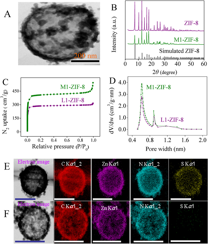
To confirm the degradation of L by GSH, L1-ZIF-8 and L2-ZIF-8 were analyzed by energy dispersive spectrometry (EDS). The results of EDS element mapping (Figs. 2E and F) showed that L1-ZIF-8 contained considerable S, a characteristic element of L, while M1-ZIF-8 contained almost no element S. This confirmed that the L in L1-ZIF-8 were almost completely degraded by GSH. Furthermore, thermogravimetric analysis (TGA) was performed on ZIF-8, L1-ZIF-8 and M1-ZIF-8. The TGA results indicated that ZIF-8 and M1-ZIF-8 had a similar thermogravimetric degradation curve, while the degradation of L was evident in the TGA curve of L1-ZIF-8 (Fig. S11 in Supporting information). This further confirmed the complete degradation of L in L-ZIF-8.
The formation mechanism of M-ZIF-8 constructed using the prepared L as the template (Fig. S12 in Supporting information) was as follows. Because the self-assembled L-nanoparticles in aqueous solution contained hydrophilic hydroxyl groups, they bound the metal Zn2+ ions of ZIF-8 via coordination bonds. The interaction between hydroxyl groups and Zn2+ led to the concentration of Zn2+ on the outer surface of the L, followed by ZIF-8 nucleation through further binding with free organic linkers and 2-methylimidazole in solution [51]. Thus, conditions were created for the growth of ZIF-8 on the surface of L.
According to the strategy described in Fig. 1, core-shell enzyme reactors were prepared with M1-ZIF-8 as the shell and horseradish peroxidase (HRP), glucose oxidase (GOx), or catalase (CAT) as the core. These three enzymes were selected because they were the most common model-enzymes for nano reactors research and for glucose detection in a cascade reaction. To prove that the enzyme was indeed encased by M1-ZIF-8, BSA-protected gold clusters (AuNCs@BSA) were synthesized as guest molecules instead of the enzyme. Due to the good fluorescence characteristics of AuNCs@BSA, the inclusion of AuNCs@BSA in M1-ZIF-8 could be clearly visualized. The fluorescence spectra of the synthesized AuNCs@BSA are shown in Fig. 3A-a with an obvious emission peak at 650 nm. However, after incubation with AuNCs@BSA and L1 (L1-AuNCs), almost no fluorescence signal was detected in the supernatant (Fig. 3A-c) which indicated that many AuNCs@BSA were enclosed by L. Zn2+ and 2-methylimidazole were added to the system to further mineralize the L1-AuNCs, and GSH was added to degrade the L1. There were no fluorescence signals of the supernatant before degradation (AuNCs@L1-ZIF-8, Fig. 3A-d) or after degradation (AuNCs@M1-ZIF-8, Fig. 3A-e). Finally, the obtained AuNCs@M1-ZIF (Fig. 3A-b) were degraded in acetate buffer (pH 5.0), and the fluorescence signal was measured. The fluorescence intensity was slightly lower than that of AuNCs@BSA, which may have been due to the envelopment of the AuNCs@BSA. These results indicated that AuNCs@BSA were indeed embedded in microporous ZIF-8, which proved the feasibility of the proposed strategy. The enzyme entrapment rate of this method was determined by the absorbance of the supernatant enzyme solution before and after the immobilization of different enzymes (Figs. S13-S15 in Supporting information). The enzyme immobilization efficiency and immobilization ability of the corresponding enzyme reactors were obtained by combining the corresponding linear relationships (Figs. S16-S18 in Supporting information). Furthermore, the free HRP and HRP released from HRP@M1-ZIF-8 composites were characterized by circular dichroic chromatography (Fig. S19A in Supporting information), which indicated that the structure of HRP did not change before and after immobilization. Notably, LCSM images clearly verified the different spatial dispersion of HRP in L (Fig. S19B in Supporting information) and in M1-ZIF-8 (Fig. S19C in Supporting information).
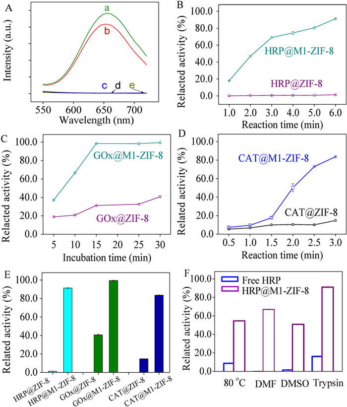
Fig. S20 (Supporting information) displays the concentration-dependent formation of catalytic products by HRP@ZIF-8 and HRP@M1-ZIF-8 through the calculated Michaelis-Menten kinetic parameters. The maximum velocity was 0.55 × 10⁻⁸ mol L−1 s−1 for HRP@ZIF-8, while 7.04 × 10⁻⁸ mol L−1 s−1 for HRP@M1-ZIF-8. Then the activity of the GOx@ZIF-8 or CAT@ZIF-8, which was constructed via the proposed strategy, was compared with that of the traditional ZIF-8 immobilization enzyme reactor. Under the same catalytic conditions, the activity of HRP@M1-ZIF-8, GOx@M1-ZIF-8, and CAT@M1-ZIF-8 (Figs. 3B-E) was significantly improved compared with the corresponding traditional enzyme reactor. This increased activity was mainly attributed to the following two reasons. First, in the traditional ZIF-8 immobilized enzyme mode, the enzyme molecule was firmly fixed in ZIF-8, and had minimal conformational freedom, which hindered the recognition between the substrate molecule and the enzyme. The proposed strategy overcame this problem, providing more free space for enzymes via the sacrificial template, which greatly promoted the mutual recognition of the substrate molecules and enzymes. Second, tightly packed ZIF-8 impeded the mass transfer of substrate molecule and was also one of the shortcomings of traditional immobilization strategies. As displayed in Fig. S21 (Supporting information), the mass transfer of substrate in enzyme@M1-ZIF-8 (Fig. S21B) was easier than that in enzyme@ZIF-8 (Fig. S21A), which also accounted for the higher catalytic activity of enzyme@M1-ZIF-8. Additionally, to investigate the stability of enzymes in vivo, the free HRP and HRP@M-ZIF-8 was exposed to heat (80 ℃), organic solvents (DMF, DMSO) and trypsin solution (10.0 mg/mL) because these harsh conditions would lead risk to unfold the proteins, resulting in inactivation. The retained bioactivity, denoted as the catalytic rate conversion after different treatments, was calculated. Fig. 3F indicates that after treatment by heating or DMF or DMSO or trypsin, the retained bioactivity of free HRP was only 8.8%, 0.2%, 1.6% and 16.3%, respectively, while, the HRP@M-ZIF-8 maintained 54.7%, 67.1%, 51.0% and 91.1% of its original activity, respectively. Fig. S22 (Supporting information) exhibits good reusability of the HRP@M-ZIF-8. These results demonstrated that the constructed enzyme@M-ZIF-8 had certain resistance to harsh condition.
To further explore the universality of the strategy, eighteen enzyme-reactors were fabricated based on two ZIFs, three kinds of L and three enzymes, and their performance was compared. Three kinds of L with different structures (L1, L2, L3) were successfully synthesized (Fig. S1), ZIF-8 and ZIF-67 were used for the inclusion of HRP, GOx and CAT. The structures of the resulting enzyme reactors were characterized using PXRD (Fig. S23 in Supporting information), TEM (Figs. S24-S28 in Supporting information) and EDS (Figs. S24-S28). The PXRD results showed that the M-ZIFs structure was not affected by L degradation or enzymes immobilization, confirming its integrity. TEM images (Figs. S24-S28) revealed that spherical M-ZIFs were synthesized. EDS data depicted that GSH could effectively degrade the L templates. All these results confirmed that the proposed synthesis strategy was highly feasible for constructing M-ZIFs. Next, the catalytic efficiency of the different microporous spherical M-ZIF-immobilized HRP, GOx and CAT reactors was compared with that of the traditional enzyme@ZIFs (Figs. S29 and S30 in Supporting information). The results exhibited that the catalytic efficiency of the enzyme@M-ZIFs was significantly improved, indicating that the proposed strategy was universal.
In practical applications, two or more enzymes are often required. Additionally, multiple enzymes catalyze multiple substrates to produce products can be catalyzed by the next enzyme to form final products. Enzyme cascade reactions have the advantages of rapid reaction speed, high selectivity, low pollution and low cost. Therefore, the construction of micro-enzyme cascade reactors has wide application prospects in the fields of biotechnology development, pharmaceutical research and chemical manufacturing [52–55].
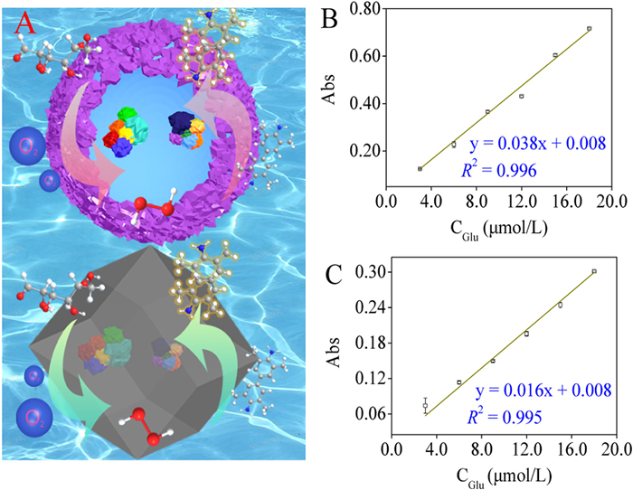
Under aerobic conditions, GOx can catalyze the highly selective oxidation of glucose (Glu) to gluconic acid, accompanied by the formation of an equal amount of H2O2. Consequently, 3,3′,5,5′-tetramethylbenzidine dihydrochloride (TMB) can be quantitatively oxidized to oxTMB with the yielded H2O2 as the substrate of HRP. Thus, the combination of the two enzymes enables the efficient determination of Glu. To improve the efficiency of cascade reactions, enzymes are usually fixed in the same matrix using the enzyme immobilization strategy. However, this results in a considerable reduction in the efficiency of the cascade reactions. In the present study, a cascade enzyme reactor was constructed with a large cavity in ZIF-8 (Fig. 4A). Then the efficiency of Glu-colourimetric detection at equivalent substrate concentrations was compared using GOx-HRP@ZIF-8 and GOx-HRP@M1-ZIF-8 as the enzyme-reactors. The results indicated that both GOx-HRP@ZIF-8 and GOx-HRP@M1-ZIF-8 had a good linear correlation in the linear range of 3.0–18.0 µmol/L (Figs. 4B and C) with limit of detection (LOD) down to 0.9 µmol/L, which could be comparable with the reported ones (Table S1 in Supporting information). However, the Glu-consumption with GOx-HRP@M1-ZIF-8 (y = 0.038x + 0.008) was more efficient than that with GOx-HRP@ZIF-8 (y = 0.016x + 0.008), and it yielded a highly sensitive signal response. This difference may have been due to the high degree-of-freedom conformation of the GOx-HRP cascade reaction in the M-ZIF-8 cavity and the short substrate/product mass transfer distance. This result validated that M-ZIFs enabled the embedding multiple conformationally free enzymes for better cascade performance, which has potential applications in the manufacture of bioreactors or advanced microdevices.
In summary, a simple biodegradable L-templates protocol to prepare M-ZIFs for encapsulating various enzymes was proposed. Enzymes were encapsulated in prepared L by in situ encapsulation to form the enzymes-L system, which provided the degradable template for fabricating a bilayer core-shell structure with L, ZIFs and enzymes. Based on the redox reaction between GSH and disulphide bonds, the inner L was effectively removed by the introduction of GSH. This strategy, on the premise of ensuring the recyclability of enzymes, was designed to provide the embedded enzymes with a highly free space and good tolerance. Additionally, the mass transfer of substrates and products was shortened significantly, effectively increasing their diffusion efficiency, and promoting the biological activity of the enzymes. The universality of this protocol was proved using three kinds of L (L1, L2, L3) as templates for the in situ encapsulation of the three different enzymes (HRP, GOx, CAT) into two ZIFs (ZIF-8, ZIF-67). The eighteen nanoreactors maintained favourable biological activity. Furthermore, it was demonstrated that this fabrication protocol could be used for the effective co-encapsulation of multiple enzymes in M-ZIFs. Compared with traditional enzyme@ZIFs, this approach exhibited more efficient cascade reaction efficiency. Not only does this study provide a new protocol for maintaining the biological activity of enzymes via in situ encapsulation with M-ZIFs, but also offers a new research approach for constructing efficient cascade reaction devices.
The authors declare that they have no known competing financial interests or personal relationships that could have appeared to influence the work reported in this paper.
The authors are grateful for the financial support from the National Natural Science Foundation of China (No. 22274159), and for the kind help from Yutong Liu, Muhammad Ali Tajwar, Rubina Jiabeen, Changyan Cao and Xiangru Zhang.
Supplementary material associated with this article can be found, in the online version, at doi:
V. Aggarwal, S. Solanki, B.D. Malhotra, Chem. Sci. 13 (2022) 8723–8743.
Y. Deng, T. Wu, X. Chen, et al., J. Am. Chem. Soc. 145 (2023) 1262–1272. doi: 10.1021/jacs.2c11168
Y. Lin, J. Ren, X. Qu, Acc. Chem. Res. 47 (2014) 1097–1105. doi: 10.1021/ar400250z
W.L. Liu, T. Head-Gordon, ACS Cent. Sci. 7 (2021) 72–80. doi: 10.1021/acscentsci.0c01556
M. Li, N.T. Blum, J. Wu, J. Lin, P. Huang, Adv. Mater. 33 (2021) e2008438. doi: 10.1002/adma.202008438
S. Wu, R. Snajdrova, J.C. Moore, K. Baldenius, U.T. Bornscheuer, Angew. Chem. Int. Ed. 60 (2021) 88–119. doi: 10.1002/anie.202006648
D. Tian, X. Zhang, H. Shi, et al., J. Am. Chem. Soc. 143 (2021) 16641–16652. doi: 10.1021/jacs.1c07482
M. Valldeperas, A. Salis, J. Barauskas, et al., Curr. Opin. Colloid Interface Sci. 44 (2019) 130–142. doi: 10.1016/j.cocis.2019.09.007
J. Song, W. He, H. Shen, et al., Chem. Eng. J. 363 (2019) 174–182. doi: 10.1016/j.cej.2019.01.138
W. Liang, P. Wied, F. Carraro, et al., Chem. Rev. 121 (2021) 1077–1129. doi: 10.1021/acs.chemrev.0c01029
A.A. Caparco, D.R. Dautel, J.A. Champion, Small 18 (2022) e2106425. doi: 10.1002/smll.202106425
Y. Zheng, S. Zhang, J. Guo, et al., Angew. Chem. Int. Ed. 61 (2022) e202208744. doi: 10.1002/anie.202208744
X. Pei, Z. Luo, L. Qiao, et al., Chem. Soc. Rev. 51 (2022) 7281–7304. doi: 10.1039/D1CS01004B
Y.R. Maghraby, R.M. El-Shabasy, A.H. Ibrahim, H.M.E. Azzazy, ACS Omega 8 (2023) 5184–5196. doi: 10.1021/acsomega.2c07560
Z. Zhou, M. Hartmann, Chem. Soc. Rev. 42 (2013) 3894–3912. doi: 10.1039/c3cs60059a
X. Lian, Y. Fang, E. Joseph, et al., Chem. Soc. Rev. 46 (2017) 3386–3401. doi: 10.1039/C7CS00058H
C. Sicard, Angew. Chem. Int. Ed. 62 (2023) e202213405. doi: 10.1002/anie.202213405
X. Zou, S. Wei, S. Badieyan, et al., J. Am. Chem. Soc. 140 (2018) 16560–16569. doi: 10.1021/jacs.8b08138
A.F. Chaparro Sosa, R.M. Bednar, R.A. Mehl, D.K. Schwartz, J.L. Kaar, J. Am. Chem. Soc. 143 (2021) 7154–7163. doi: 10.1021/jacs.1c02375
P. Li, S.Y. Moon, M.A. Guelta, et al., J. Am. Chem. Soc. 138 (2016) 8052–8055. doi: 10.1021/jacs.6b03673
C. Bernal, K. Rodriguez, R. Martinez, Biotechnol. Adv. 36 (2018) 1470–1480. doi: 10.1016/j.biotechadv.2018.06.002
L. Betancor, H.R. Luckarift, Trends Biotechnol 26 (2008) 566–572. doi: 10.1016/j.tibtech.2008.06.009
E. Gkaniatsou, C. Sicard, R. Ricoux, et al., Angew. Chem. Int. Ed. 57 (2018) 16141–16146. doi: 10.1002/anie.201811327
S. Ariaeenejad, E. Hosseini, E. Motamedi, A.A. Moosavi-Movahedi, G.H. Salekdeh, Chem. Eng. J. 375 (2019) 122022. doi: 10.1016/j.cej.2019.122022
L. Chai, J. Pan, Y. Hu, J. Qian, M. Hong, Small 17 (2021) e2100607. doi: 10.1002/smll.202100607
Z. Ye, Y. Jiang, L. Li, F. Wu, R. Chen, Nano-Micro Lett. 13 (2021) 203. doi: 10.1007/s40820-021-00726-z
J. Zhang, Z. Li, X.L. Qi, D.Y. Wang, Nano-Micro Lett. 12 (2020) 173. doi: 10.1007/s40820-020-00497-z
S.S. Nadar, L. Vaidya, V.K. Rathod, Int. J. Biol. Macromol. 149 (2020) 861–876. doi: 10.1016/j.ijbiomac.2020.01.240
S.S. Nadar, V.K. Rathod, Int. J. Biol. Macromol. 120 (2018) 2393-2302.
E. Gkaniatsou, C. Sicard, R. Ricoux, et al., Mater. Horizons. 4 (2017) 55–63. doi: 10.1039/C6MH00312E
S. Huang, X. Kou, J. Shen, G. Chen, G. Ouyang, Angew. Chem. Int. Ed. 59 (2020) 8786–8798. doi: 10.1002/anie.201916474
X.L. Wu, J. Ge, C. Yang, M. Hou, Z. Liu, Chem. Commun. 51 (2015) 13408. doi: 10.1039/C5CC05136C
F.J. Lyu, Y.F. Zhang, R.N. Zare, J. Ge, Z. Liu, Nano Lett. 14 (2014) 5761–5765. doi: 10.1021/nl5026419
R.C. Rodrigues, C. Ortiz, A. Berenguer-Murcia, R. Torres, R. Fernandez-Lafuente, Chem. Soc. Rev. 42 (2013) 6290–6307. doi: 10.1039/C2CS35231A
Y. Chen, P. Li, J.A. Modica, R.J. Drout, O.K. Farha, J. Am. Chem. Soc. 140 (2018) 5678–5681. doi: 10.1021/jacs.8b02089
Y. Zhang, C. Xing, Z. Mu, et al., J. Am. Chem. Soc. 145 (2023) 13469–13475. doi: 10.1021/jacs.3c04183
H. An, M. Li, J. Gao, et al., Coord. Chem. Rev. 384 (2019) 90–106. doi: 10.1016/j.ccr.2019.01.001
Y. Chen, V. Lykourinou, C. Vetromile, et al., J. Am. Chem. Soc. 134 (2012) 13188–13191. doi: 10.1021/ja305144x
Z. Zhou, H. Chao, W. He, et al., Appl. Surf. Sci. 586 (2022) 152815. doi: 10.1016/j.apsusc.2022.152815
X. Wang, C. Lan, S. Ma, ACS Cent. Sci. 6 (2020) 1497–1506. doi: 10.1021/acscentsci.0c00687
B.J. Johnson, W. Russ Algar, A.P. Malanoski, M.G. Ancona, I.L. Medintz, Nano Today 9 (2014) 102–131. doi: 10.1016/j.nantod.2014.02.005
Q. Sun, Y. Pan, X. Wang, et al., Chem 5 (2019) 3184–3195. doi: 10.1016/j.chempr.2019.10.002
U. Hanefeld, L. Gardossi, E. Magner, Chem. Soc. Rev. 38 (2009) 453–468. doi: 10.1039/B711564B
L. Klermund, K. Castiglione, Bioprocess Biosyst. Eng. 41 (2018) 1233–1246. doi: 10.1007/s00449-018-1953-9
S. Ghosh, K. Irvin, S. Thayumanavan, Langmuir 23 (2007) 7916–7919. doi: 10.1021/la700981z
J.H. Ryu, R. Roy, J. Ventura, S. Thayumanavan, Langmuir 26 (2010) 7086–7092. doi: 10.1021/la904437u
M. Wang, J.A. Zuris, F. Meng, et al., Proc. Natl. Acad. Sci. U. S. A. 113 (2016) 2868–2873. doi: 10.1073/pnas.1520244113
P. Shao, Z. He, Y. Hu, et al., Chem. Eng. J. 435 (2022) 134957. doi: 10.1016/j.cej.2022.134957
X.G. Yang, J.R. Zhang, X.K. Tian, et al., Angew. Chem. Int. Ed. 62 (2023) e202216699. doi: 10.1002/anie.202216699
R. Han, Z. Ye, Y. Zhang, et al., Asian J. Pharm. Sci. 18 (2023) 100811. doi: 10.1016/j.ajps.2023.100811
X. Li, M. Wang, H. Gao, et al., ACS Appl. Mater. Interfaces 14 (2022) 43215–43225. doi: 10.1021/acsami.2c10565
Z.Q. Dai, J.L. Guo, T.T. Su, et al., Green Chem. 23 (2021) 8685. doi: 10.1039/D1GC02745J
J.L. Guo, L.L. Yang, Z.D. Gao, et al., ACS Catal. 10 (2020) 5949–5958. doi: 10.1021/acscatal.0c00591
J.L. Guo, L.L. Yang, C.X. Zhao, et al., J. Mater. Chem. A 9 (2021) 14911. doi: 10.1039/D1TA04009J
J.L. Guo, X.A. Liu, J.J. Zhao, et al., Chem. Sci. 14 (2023) 1742. doi: 10.1039/D2SC05784K

Figure 1 Schematic representation of the in situ encapsulation of enzymes within M-ZIF via biodegradable L as sacrificial template.

Figure 2 Characterization of M1-ZIF-8. (A) TEM images showing M1-ZIF-8. (B) PXRD patterns of ZIF-8 (purple), M1-ZIF-8 (blue), simulated pattern of ZIF-8 (black). (C) N2 adsorption isotherms of L1-ZIF-8 (purple) and M1-ZIF-8 (green). (D) pore size distribution of L1-ZIF-8 (purple) and M1-ZIF-8 (green). TEM images and EDS elemental mapping of L1-ZIF-8 (E) and M1-ZIF-8 (F), bar size: 500 nm.

Figure 3 Construction and activity determination of enzyme reactors. (A) Fluorescence spectra of different systems at 650 nm (a-AuNCs@BSA, b-degraded AuNCs@M1-ZIF-8, c-L1-AuNCs supernatant, d-AuNCs@L1-ZIF-8 supernatant, e-AuNCs@M1-ZIF-8 supernatant). Comparative activity of (B) HRP@ZIF-8 and HRP@M1-ZIF-8, (C) GOx@ZIF-8 and GOx@M1-ZIF-8, (D) CAT@ZIF-8 and CAT@M1-ZIF-8. (E) Comparative activity of different enzyme reactors. (F) Stability of the HRP@M1-ZIF-8 composites compared with free enzymes incubated in PBS solution (pH 7.4).

 扫一扫看文章

扫一扫关注我们
 DownLoad:
 下载:
下载:
