Faculty of Metallurgy and Energy Engineering, Kunming University of Science and Technology, Kunming 650093, China
b.
Key Laboratory of Optoelectronic Materials Chemistry and Physics, Fujian Institute of Research on the Structure of Matter, Chinese Academy of Sciences, Fuzhou 350002, China
c.
State Key Laboratory of Advanced Electromagnetic Engineering and Technology, School of Electrical and Electronic Engineering, Huazhong University of Science and Technology, Wuhan 430074, China
mxwu@fjirsm.ac.cn (M. Wu). 1 These authors contributed equally to this work.
Received Date:
12 June 2023 Accepted Date:
11 July 2023 Revised Date:
06 July 2023 Available Online:
15 June 2024
Abstract:
The addition of electrolyte additives is an effective strategy for tuning the property of the electrolyte to engineer the electrode/electrolyte interface, and there exist obvious discrepancies regarding the effect of fluoroethylene carbonate (FEC) as an electrolyte additive on the performance of cathodes. Herein FEC is introduced into the electrolyte of the LiMn0.8Fe0.2PO4/Li cell and its effect on the properties of the LiMn0.8Fe0.2PO4 is investigated. It is found that the addition of FEC in the electrolyte has a positive effect on the performance of the LiMn0.8Fe0.2PO4 cathode, which can be attributed to the reduced products generated by the interfacial side-reactions on the LiMn0.8Fe0.2PO4 cathode surface and the decreased metal dissolution in the FEC-containing electrolyte, thanks to the higher oxidation resistance of FEC and the easier and stronger binding of FEC and PF6−.
The goal of achieving carbon neutrality and the rapid development of global electro-mobility push forward the development of energy storage technologies [1-22], which also emphasize the importance of rechargeable lithium-ion batteries (LIBs). Over nearly three decades, olivine structure LiMPO4 (M = Fe, Mn, Co, and Ni) cathodes are extremely popular for LIBs with the merits of low cost, good stability and competitive electrochemical performance [1-15]. Among these cathodes, LiMnPO4 stands out with its higher operating voltage platform (4.1 V vs. Li+/Li) [2]. Unfortunately, its extremely low conductivity hinders the practical application of the pristine material [3-5]. In response, major approaches including minimizing particle size, coating carbon and doping cations have been attempted to overcome this limitation from the nature of the material itself [6-10], and great improvement in the electrochemical activity has been made by the combination of these approaches [9,10]. Nevertheless, the modified LiMnPO4 based materials still suffered undesirable capacity fading upon cycling because of the intrinsic instability of the materials themselves [11,12] and the side-reactions occurring between the cathode and electrolyte [13,14]. Therefore, besides the nature of the materials themselves, the cathode/electrolyte interface also affects the performance of the LiMnPO4 based materials. Evidently, the interface can be engineered by tuning the property of the electrolyte, and a compatible electrolyte will be highly beneficial to the formation of a favorable interface. In this regard, introducing functional additives into the electrolyte is recognized as one of the most economic and effective strategies, and various functional electrolyte additives have been studied [23-35]. Fluoroethylene carbonate (FEC) is a typical electrolyte additive and has been widely studied on the performance of LIBs. Although it is well-recognized that the FEC in the electrolyte plays a positive effect on the anode of LIBs, there exist obvious discrepancies regarding its effect on the cathode [26-33]. As a single additive added into the carbonate electrolytes, positive effects of FEC were reported on the LiFePO4 [26,27], Li1.16[Mn0.75Ni0.25]0.84O2 [28], LiCoO2 [29] and LiNi0.8Co0.1Mn0.1O2 [30] cathodes, while negative effects were reported on the LiMn2O4 [31] and LiNi0.5Mn1.5O4 [32,33] cathodes. Moreover, the FEC-induced variation in the amount of LiF, LixPOyFz and carbonate species generated by the interfacial side-reactions on the cathode surface are highly different in these reports, and accordingly, multiple explanations were suggested. Based on these available reports, it is difficult to predict the possible effect of FEC on a new cathode, and thus more research is needed to reveal and understand the functions of FEC as an additive in the electrolyte.
Now, there still lack specific studies on the behavior of the LiMnPO4 based materials in the FEC-containing electrolyte, and exploring the effect of FEC on the LiMnPO4 based materials may promote a better understanding on the functions of FEC in the electrolyte. In this work, LiMn0.8Fe0.2PO4 is taken as a case study material and the effect of FEC in the electrolyte on the performance of LiMn0.8Fe0.2PO4 is explored. The experimental and theoretical studies reveal that FEC is an effective electrolyte additive for tuning the property of the electrolyte to form a favorable cathode/electrolyte interface for improving the performance of the LiMn0.8Fe0.2PO4, which provides an interfacial strategy to improve the performance of LiMnPO4 based materials.
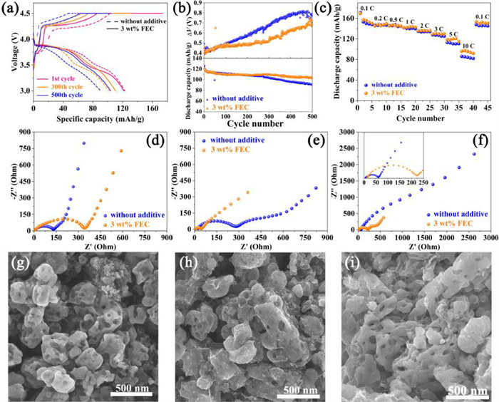
The electrochemical performance of LiMn0.8Fe0.2PO4 cathodes in the electrolyte with and without FEC additive are comparatively evaluated using CR2025 coin-type cells. The typical charge-discharge curves at different cycles at 1 C (1 C is equal to 150 mA/g) for LiMn0.8Fe0.2PO4 cathode in the electrolyte with and without FEC are shown in Fig. 1a. All curves similarly consist of two typical voltage plateaus at about 3.5 and 4.1 V corresponding to Fe3+/Fe2+ and Mn3+/Mn2+ redox couples, respectively. Noted that the first charge-discharge curves show a relatively larger polarization, lower reversible capacity and coulombic efficiency in the FEC-containing electrolyte than those in the FEC-free electrolyte, because introducing FEC into the electrolyte may increase the electrolyte viscosity which in turn reduces the ionic conductivity and wettability of the electrolyte [36]. Therefore, the addition amount of FEC should be well controlled. The situation changes upon cycling, and the polarizations at the 300th and 500th cycle are noticeably larger in the FEC-free electrolyte, and the cell charge was greatly limited due to the severe polarization, which ultimately led to an obvious decrease in the reversible capacity. This phenomenon can be seen more visually in Fig. 1b, which shows the cycle performance and the difference between the average charge and discharge voltage (called ΔV here) in the voltage range of 3.0–4.5 V (vs. Li+/Li). It is clear that the LiMn0.8Fe0.2PO4 cathode in the FEC-containing electrolyte has the better cycle performance, and its discharge capacity decreases from 121.8 mAh/g to 104.1 mAh/g with a capacity retention of 85.5% after 500 cycles at 1 C, while that in the FEC-free electrolyte decreases from 125.9 mAh/g to 89.2 mAh/g with a capacity retention of only 70.8% after 500 cycles at 1 C, showing that the capacity fading of LiMn0.8Fe0.2PO4 is effectively suppressed by adding FEC additive. According to the variation of ΔV versus cycle number, it is found that the ΔV for the FEC-free electrolyte starts to be greater than that for the FEC-containing electrolyte after about 100 cycles, and the gap becomes more significant with extending the cycle, indicating that the addition of FEC into the electrolyte can reduce the charge-discharge polarization. The slower growing polarization coupled with the higher capacity retention of the LiMn0.8Fe0.2PO4 cathode in the FEC-containing electrolyte indicates that the present of FEC in the electrolyte favors the charge and discharge of LiMn0.8Fe0.2PO4 cathode by suppressing the increase of polarization. Moreover, a close observation of the charge-discharge curves (Fig. 1a) also reveals that the voltage plateaus of the Fe3+/Fe2+ redox couple shorten with the increased cycle, indicating the possible loss of the active material induced by the interfacial side-reactions of the cathode/electrolyte. It is well-documented that the products generated by interfacial side-reactions of cathode/electrolyte under high voltages can lead to the increase of polarization upon cycling [37]. These results indicate that the FEC in the electrolyte can improve the interfacial interaction of LiMn0.8Fe0.2PO4 cathode and electrolyte, which in turn suppress the increase of polarization and the capacity fading during long cycle. Fig. 1c depicts the rate performance of LiMn0.8Fe0.2PO4 cathodes in the electrolytes. There are no appreciable differences at low rates (0.1–3 C), but when the discharge rate is increased up to 5 C or higher, higher discharge capacities are observed in the FEC-containing electrolyte. Notably, the discharge capacity in the FEC-containing electrolyte is closed to 100 mAh/g at 10 C, while only a discharge capacity of 82.8 mAh/g is observed in the FEC-free electrolyte at 10 C. It is not hard to understand that the suppressed charge-discharge polarization induced by incorporation of FEC into the electrolyte can enhance the rate capability of the LiMn0.8Fe0.2PO4 cathode.
Figure 1
Figure 1.
(a) Typical charge-discharge curves of the LiMn0.8Fe0.2PO4 cathode in the electrolyte with and without FEC at 1 C (1 C is equal to 150 mA/g). (b) Cycle performance and the difference between the average charge and discharge voltage (∆V) as a function of cycle number at 1 C and (c) rate performance. EIS spectra of the cathodes in the two electrolytes recorded at the fully discharge state: (d) Uncycled, (e) after 5 cycles at 0.2 C and (f) after 500 cycles at 1 C. SEM images of the cathodes: (g) Uncycled, (h) after 500 cycles in the FEC-free electrolyte at 1 C and (i) after 500 cycles in the FEC-containing electrolyte at 1 C.
The electrochemical behavior of LiMn0.8Fe0.2PO4 cathodes in the two electrolytes was further studied by EIS which was measured using the assembled and the cycled CR2025 coin-type cells. As shown in Figs. 1d-f, all spectra generally consist of arcs at high-frequency and medium-frequency region, representing the interfacial impedances including the cathode surface film resistance (Rf) and the charge transfer resistance (Rct), and a sloped line at low-frequency region belonging to Warburg impedance [38]. From Fig. 1d, it is interesting that the uncycled cathode has a higher interfacial resistance in the FEC-containing electrolyte than that in the FEC-free electrolyte, which is well coupled with the larger polarization of the first charge-discharge in the FEC-containing electrolyte (Fig. 1a). It indicates that the interaction between the cathode and electrolyte has already been taken place before cycling and the FEC has begun to take effect. However, reverse results are observed after 5 cycles and thereafter. From Fig. 1e, the interfacial resistance (Rf and Rct) in the FEC-free electrolyte increased substantially and is notably larger than the decreased one in the FEC-containing electrolyte after 5 cycles, indicating a positive effect of FEC on the cathode/electrolyte interface. Similarly, the interfacial resistance in the FEC-free electrolyte is found to be larger than 1000 Ohm, which is much larger than that in the FEC-containing electrolyte (<500 Ohm) after 500 cycles (Fig. 1f). Therefore, it is apparent that the introduction of FEC into the electrolyte can effectively improve the interaction of LiMn0.8Fe0.2PO4 cathode/electrolyte to suppress the increase of the cathode interfacial resistance upon cycling, which thus facilitates the charge transfer between the interface and leads to the better charge-discharge performance (Figs. 1a-c).
The results of the EIS suggest that the interfacial side-reactions of cathode/electrolyte lead to the formation of solid film on the cathode surface upon cycling. The presence of the interfacial film can be observed by SEM, and the images of the uncycled LiMn0.8Fe0.2PO4 cathode and those after 500 cycles in the two electrolytes are shown in Figs. 1g-i. Compared with the porous particles with open pores of the uncycled LiMn0.8Fe0.2PO4 cathode, it's not hard to see that the pores in the particles of the cathode after 500 cycles in the FEC-free electrolyte was severely blocked, and the degree of blockage is obviously reduced in the FEC-containing electrolyte, which directly demonstrates the existence of the interfacial film on the cathode surface and more products of the interfacial side-reactions formed in the FEC-free electrolyte. Apparently, the blockage of pores would impede the electrolyte penetration and Li+ diffusion into the LiMn0.8Fe0.2PO4 particles, thus leading to the increase of the charge-discharge polarization. More products of the interfacial side-reactions mean a thick solid film deposited on the cathode surface, also leading to the increase of the charge-discharge polarization. From the above results, we can conclude that the present of FEC can improve the interfacial interaction between the LiMn0.8Fe0.2PO4 cathode and electrolyte to suppress the occurrence of the interfacial side-reactions, and thus thin solid film is formed and less pores are blocked, which ultimately lead to the improved electrochemical performance of the LiMn0.8Fe0.2PO4.
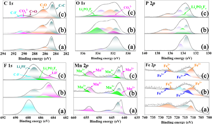
To probe the deposited compounds generated by the interfacial side-reactions of the cathode/electrolyte upon cycling, the LiMn0.8Fe0.2PO4 cathodes after 500 cycles were studied by XPS. Fig. 2 displays the XPS spectra of C 1s, O 1s, P 2p, F 1s, Mn 2p and Fe 2p for the LiMn0.8Fe0.2PO4 cathodes. The C 1s spectrum of the uncycled LiMn0.8Fe0.2PO4 cathode consists of three peaks. The peak at 284.8 eV is attributed to C-C in the graphite, and two other peaks at 286.0 and 290.8 eV are attributed to C-O and C-F bonds in the PVDF binder. Some additional peaks are observed in the spectra of the cycled cathode. The peak at 288.7 eV is associated with C=O bonds in lithium alkyl carbonates and polycarbonates, and the peak at 290.0 eV is associated with Li2CO3 [39]. It is seen that the Li2CO3 peak for the LiMn0.8Fe0.2PO4 cathode cycled in the FEC-containing electrolyte is weaker than that in the FEC-free electrolyte, which means that less Li2CO3 was generated in the FEC-containing electrolyte upon cycling. Consistent results are observed in the O 1s spectra, and the Li2CO3 peak at 531.5 eV is also weaker for the cathode cycled in the FEC-containing electrolyte. In addition, a peak at 534.0 eV of LixPOyFz is additionally observed in the O 1s spectrum of each cycled cathode [40,41], and it is well-documented that LixPOyFz is an intermediate product of the LiPF6 decomposition of the electrolyte [28]. Obviously, the LixPOyFz peak is much weaker for the LiMn0.8Fe0.2PO4 cathode cycled in the FEC-containing electrolyte as compared with that in the FEC-free electrolyte, which indicates that less LixPOyFz was generated in the FEC-containing electrolyte upon cycling. The presence of LixPOyFz is also supported by the P 2p (the peak at 134.0 eV) and F 1s spectra (the peak at 685.8 eV), and likewise, the LixPOyFz peak for the cathode cycled in the FEC-containing electrolyte is clearly lower than that in the FEC-free electrolyte. In the F 1s spectra of the cycled cathodes, another new peak at 684.8 eV is related to LiF [42], and its intensity is much lower for the cathode cycled in the FEC-containing electrolyte. According to the available literature [42,43], HF can be generated by the hydrolysis of LiPF6 in the electrolyte and then will consume Li+ to form LiF deposited on the electrode surface. The C 1s, O 1s, P 2p and F 1s spectra of the LiMn0.8Fe0.2PO4 cathodes all demonstrate the presence of Li2CO3, polycarbonate, LiF and LixPOyFz on the cycled cathode surface, which is well consistent with the observations of the XRD and FTIR measurements (Figs. S1 and S2 in Supporting information), and evidence that the addition of FEC into the electrolyte can suppress the interfacial side-reactions occurring between the LiMn0.8Fe0.2PO4 cathode and electrolyte.
Figure 2
Figure 2.
The C 1s, O 1s, P 2p, F 1s, Mn 2p and Fe 2p XPS spectra of LiMn0.8Fe0.2PO4 electrodes: (a) Uncycled, (b) after 500 cycles at 1 C in the FEC-free electrolyte and (c) after 500 cycles at 1 C in the FEC-containing electrolyte. All XPS measurements were using a monochromatic Al Kα source (1486.68 eV) and the data were calibrated using adventitious C 1s peak with a fixed value of 284.8 eV.
Apparently, the generation of Li2CO3, LiF and LixPOyFz on the cathode surface consumes active Li+ from the cathode and electrolyte. The XPS spectra of Mn 2p and Fe 2p show the appearance of Mn3+ and Fe3+ (peaks at 642, 654.5, 712.5 and 726 eV) in the cathodes after 500 cycles [44], indicating the loss of active Li+ from the cathodes upon cycling. It is seen that the Mn3+ and Fe3+ peaks for the cathode cycled in the FEC-free electrolyte are all higher than those in the FEC-containing electrolyte, which means that more Mn3+ and Fe3+-containing compounds are present in the LiMn0.8Fe0.2PO4 cathode cycled in the FEC-free electrolyte. The formation of Mn3+ and Fe3+-containing compounds is associated with the occurrence of the irreversible reaction upon cycling, and the increased amount indicates a more serious loss of the active Li+, which is another factor causing the accelerated capacity loss and the shortened charge-discharge plateaus around 4.1 and 3.5 V for the LiMn0.8Fe0.2PO4 in the FEC-free electrolyte (Figs. 1a-c). From the above analyses, the products generated from the side-reactions between the cathode and electrolyte upon cycling are mainly composed of Li2CO3, LiF, LixPOyFz, polycarbonate and inorganic or organic phosphates. These compounds are all poor conductors, and the deposit of these compounds on the cathode surface will increase the interfacial impedance of the cathode. Noted that reduced amounts of these compounds are observed on the cathode surface cycled in the FEC-containing electrolyte, therefore, when the LiMn0.8Fe0.2PO4 cathode cycled in the FEC-containing electrolyte, the less amounts of decomposition products are generated by the interfacial side-reactions of the cathode/electrolyte, the less pores in the porous particles of the LiMn0.8Fe0.2PO4 are blocked and the smaller interfacial impedance is yielded, which ultimately lead to the improved electrochemical performance of LiMn0.8Fe0.2PO4 cathode in the FEC-containing electrolyte.
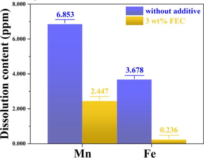
Moreover, metal dissolution from the cathode was often found to be a part of side-reactions between the cathode and electrolyte due to the attack of HF in the electrolyte, and thus caused the capacity loss [30,45,46]. Fig. 3 compares the dissolution content of Mn and Fe for the charged LiMn0.8Fe0.2PO4 cathode aged in the electrolytes without and with 3 wt% FEC for 20 d at room temperature. The dissolved content of Mn and Fe in the FEC-free electrolyte is remarkably higher than that in the electrolyte with 3 wt% FEC, demonstrating that the Mn and Fe dissolution in the FEC-containing electrolyte was significantly suppressed. Therefore, the decreased metal dissolution should be another factor for the improved capacity retention of the LiMn0.8Fe0.2PO4 cathode cycled in the FEC-containing electrolyte. Considering thinner solid film was formed and less pores were blocked for the LiMn0.8Fe0.2PO4 cathode in the FEC-containing electrolyte due to less products generated from the interfacial side-reactions between the cathode and electrolyte upon cycling, the physical protection of the cathode should be weakened and an increased metal dissolution should be expected if similar or more (FEC decomposition can release HF) HF was formed in the FEC-containing electrolyte. Consequently, the present observed decrease in the metal dissolution means that less HF was formed in the FEC-containing electrolyte comparative to the FEC-free electrolyte.
Figure 3
Figure 3.
The dissolution content of Mn and Fe for the charged LiMn0.8Fe0.2PO4 cathode aged in the electrolytes without and with 3 wt% FEC for 20 d at room temperature.
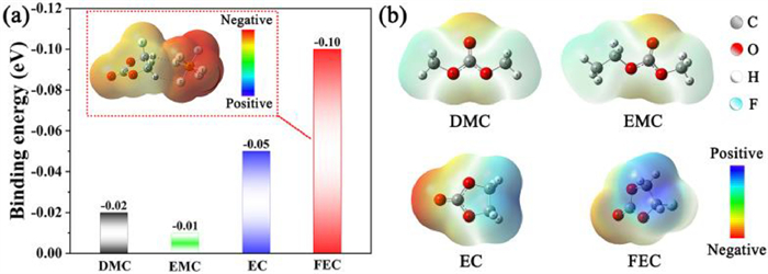
The above experimental results show that the addition of FEC in the electrolyte has a positive effect on the performance of the LiMn0.8Fe0.2PO4 cathode, which can be attributed to the reduced decomposition products generated by the interfacial side-reactions and the decreased metal dissolution in the FEC-containing electrolyte. The available reports have revealed that the FEC is more oxidation-resistant than the carbonate solvents of EC, PC, DMC, EMC and DEC [24,25,28], and the binding of FEC-PF6− is stronger than that of EC, DMC and DEC with PF6− [28]. For the electrolyte of 1.0 mol/L LiPF6-EC/EMC/DMC used in this work, our theoretical calculations also show that, similar to that of the EC and DMC with PF6−, the binding of EMC-PF6− is also weaker than that of FEC-PF6− as shown in Fig. 4, indicating an easier coordination of FEC and PF6−. The present observed improvements in the performance of LiMn0.8Fe0.2PO4 cathode in the FEC-containing electrolyte are thought to be the result of combined effect of the stronger binding of FEC-PF6− complex and the higher oxidation resistance of FEC, which work jointly on suppressing the decomposition of LiPF6 and the oxidation of carbonate solvents (EC, DMC and EMC) during charging. The easier and stronger binding of FEC and PF6− could suppress the decomposition of LiPF6, and thus less HF and LiF was generated and less metal dissolution was observed in the FEC-containing electrolyte. Meanwhile, during charging, the negative ions in the electrolyte tends to accumulate in the vicinity of cathode, and the FEC gets closer to the cathode surface than other carbonate solvents (EC, DMC and EMC) due to the easier and stronger binding of FEC and PF6−. Since the FEC is more oxidation resistant than other carbonate solvents, the attracted FEC close to the cathode surface may act as a protecting layer to suppress the oxidation of EC, DMC and EMC during charging. Noted that the FEC peaks are still present after the initial charge and discharge (Fig. S3 in Supporting information), and thus the remaining FEC would continue working as a protecting solvent to suppress the oxidation of EC, DMC and EMC in the subsequent cycles, and as a result, less surface products are generated by the interfacial side-reactions as observed on the cathode surface.
Figure 4
Figure 4.
The density functional theory (DFT) calculations: (a) Comparison of the binding energy between PF6− and DMC, EMC, EC and FEC; (b) The molecular electrostatic potential (MESP) distribution of DMC, EMC, EC and FEC.
In addition, it is noted that positive effects of FEC on the LiFePO4 and the layered cathodes (Li1.16[Mn0.75Ni0.25]0.84O2, LiCoO2 and LiNi0.8Mn0.1Co0.1O2) have been reported in the available literature [26-30], but it is interesting that the FEC-induced variation in the amount of the main component LiF generated on the surface of these cathodes was much different. For example, decreased amount of LiF was observed on the LiFePO4 cathode surface [27], while increased amount of LiF was observed on the Li1.16[Mn0.75Ni0.25]0.84O2 cathode surface [28]. In the present work, the LiMn0.8Fe0.2PO4 cathode surface also showed a decreased amount of LiF in the FEC-containing electrolyte, which is the same as that of the LiFePO4 cathode. Since the solvents of the electrolyte used in the available reports and the present work are different, it is difficult to know whether the cathode or the solvent caused the difference in the FEC-induced variation in the amount of LiF, and a comparative study on the different cathodes in the same FEC-free and FEC-containing electrolytes is needed. Moreover, we should not neglect that the well-recognized positive effects of FEC on lithium anode might also contributed partly to the overall improvement in the performance of LiMn0.8Fe0.2PO4 in the present work.
In conclusion, our comparative studies reveal that the addition of FEC additive into the electrolyte can reduce the amount of the products generated by the interfacial side-reactions between the LiMn0.8Fe0.2PO4 cathode and electrolyte and the metal dissolution in the electrolyte, due to the higher oxidation resistance of FEC and the easier and stronger binding of FEC and PF6−. These improvements lead to the results that less poor conductive compounds are deposited on the cathode surface, less pores in the porous particles of the LiMn0.8Fe0.2PO4 are blocked, less active material is lost, and thus, improved performance of the LiMn0.8Fe0.2PO4 is observed in the FEC-containing electrolyte. Therefore, the addition of FEC additive into the electrolyte provides a simple and cost-effective strategy for engineering the cathode/electrolyte interface to improve the performance of LiMnPO4 based materials.
Declaration of competing interest
The authors declare that they have no known competing financial interests or personal relationships that could have appeared to influence the work reported in this paper.
Acknowledgments
This work is supported by National Natural Science Foundation of China (Nos. 51874155 and 52177214) and the Fujian Provincial STS program supporting project of Chinese Academy of sciences (No. 2022T3001).
Supplementary materials
Supplementary material associated with this article can be found, in the online version, at doi:10.1016/j.cclet.2023.108799.
[1]
A.K. Padhi, K.S. Nanjundaswamy, J.B. Goodenough, J. Electrochem. Soc. 144 (1997) 1188–1194. doi: 10.1149/1.1837571
[2]
V. Aravindan, J. Gnanaraj, Y.S. Lee, et al., J. Mater. Chem. A 1 (2013) 3518. doi: 10.1039/c2ta01393b
[3]
N. Ravet, A. Abouimrane, M. Armand, Nat. Mater. 2 (2003) 702. doi: 10.1038/nmat1009a
[4]
A. Yamada, M. Hosoya, S.C. Chung, et al., J. Power Sources 119-121 (2003) 232–238. doi: 10.1016/S0378-7753(03)00239-8
[5]
C. Delacourt, L. Laffont, R. Bouchet, et al., J. Electrochem. Soc. 152 (2005) A913. doi: 10.1149/1.1884787
Figure 1
(a) Typical charge-discharge curves of the LiMn0.8Fe0.2PO4 cathode in the electrolyte with and without FEC at 1 C (1 C is equal to 150 mA/g). (b) Cycle performance and the difference between the average charge and discharge voltage (∆V) as a function of cycle number at 1 C and (c) rate performance. EIS spectra of the cathodes in the two electrolytes recorded at the fully discharge state: (d) Uncycled, (e) after 5 cycles at 0.2 C and (f) after 500 cycles at 1 C. SEM images of the cathodes: (g) Uncycled, (h) after 500 cycles in the FEC-free electrolyte at 1 C and (i) after 500 cycles in the FEC-containing electrolyte at 1 C.
Figure 2
The C 1s, O 1s, P 2p, F 1s, Mn 2p and Fe 2p XPS spectra of LiMn0.8Fe0.2PO4 electrodes: (a) Uncycled, (b) after 500 cycles at 1 C in the FEC-free electrolyte and (c) after 500 cycles at 1 C in the FEC-containing electrolyte. All XPS measurements were using a monochromatic Al Kα source (1486.68 eV) and the data were calibrated using adventitious C 1s peak with a fixed value of 284.8 eV.
Figure 3
The dissolution content of Mn and Fe for the charged LiMn0.8Fe0.2PO4 cathode aged in the electrolytes without and with 3 wt% FEC for 20 d at room temperature.
Figure 4
The density functional theory (DFT) calculations: (a) Comparison of the binding energy between PF6− and DMC, EMC, EC and FEC; (b) The molecular electrostatic potential (MESP) distribution of DMC, EMC, EC and FEC.

 DownLoad:

 下载:
下载:


