College of Chemical and Pharmaceutical Engineering, Hebei University of Science and Technology, Shijiazhuang 050018, China
b.
Beijing Key Laboratory of Green Chemical Reaction Engineering and Technology, Department of Chemical Engineering, Tsinghua University, Beijing 100084, China
c.
Advanced Research Institute of Multidisciplinary Science, Beijing Institute of Technology, Beijing 100081, China
d.
School of Materials Science and Engineering, Beijing Institute of Technology, Beijing 100081, China
Received Date:
13 March 2023 Accepted Date:
11 May 2023 Revised Date:
09 April 2023 Available Online:
15 April 2024
Abstract:
Electrolyte design is essential for stabilizing lithium metal anodes and localized high-concentration electrolyte (LHCE) is a promising one. However, the state-of-the-art LHCE remains insufficient to ensure long-cycling lithium metal anodes. Herein, regulating the solvation structure of lithium ions in LHCE by weakening the solvating power of diluents is proposed for improving LHCE performance. A diluent, 1,1,2,2,3,3,4,4-octafluoro-5-(1,1,2,2-tetrafluoroethoxy) pentane (OFE), with weaker solvating power is introduced to increase the proportion of aggregates (an anion interacts with more than two lithium ions, AGG-n) in electrolyte compared with the commonly used 1,1,2,2-tetrafluoroethyl-2,2,3,3-tetrafluoropropyl ether (TTE). The decomposition of AGG-n in OFE-based LHCE intensifies the formation of anion-derived solid electrolyte interphase and improves the uniformity of lithium deposition. Lithium metal batteries with OFE-based LHCE deliver a superior lifespan of 190 cycles compared with 90 cycles of TTE-based LHCE under demanding conditions. Furthermore, a pouch cell with OFE-based LHCE delivers a specific energy of 417 Wh/kg and undergoes 49 cycles. This work provides guidance for designing high-performance electrolytes for lithium metal batteries.
The demand for high-energy-density batteries has grown rapidly due to the rising popularity of consumer electronics and electric vehicles [1,2]. Despite the ongoing efforts to develop new materials and designs, the energy density of lithium (Li)-ion batteries based on graphite anodes is approaching a ceiling value of 350 Wh/kg [3-5]. Li metal is reviving as a promising anode in next-generation high-energy-density batteries due to the high specific capacity (3860 mAh/g) and low electrode potential (−3.04 V vs. Li/Li+) [6,7]. The energy density of practical Li metal batteries has exceeded 400 Wh/kg [8,9]. However, Li metal batteries suffer a short lifespan owing to the instability of Li metal anodes [10,11]. Stabilizing Li metal anodes is imperative for practical applications of Li metal batteries.
Electrolyte plays an essential role in stabilizing Li metal anodes by regulating the uniformity of solid electrolyte interphase (SEI) [12-15]. SEI is composed of the decomposition products of electrolyte with Li metal anodes [16,17]. The components in SEI, such as LiF [18,19], Li2O [20,21], and LiNxOy [22,23] as well as their distribution have a notable impact on the transport uniformity of Li-ion (Li+) in SEI, which further affect the uniformity of Li deposition and Coulombic efficiency (CE) of Li metal anodes. To this end, tremendous efforts have been devoted to electrolyte design for stabilizing Li metal anodes, such as high-concentration electrolyte (HCE) [24,25], localized high-concentration electrolyte (LHCE) [26-28], weakly solvating electrolyte [12,29,30]. Meanwhile, electrolyte additives, such as fluoroethylene carbonate (FEC) [31,32], lithium nitrate [33,34], and organic nitrate [35,36]; new electrolyte solvents and Li salts, such as fluorinated 1,4-dimethoxylbutane [12] and 1,1,1-trifluoro-2,3-dimethoxypropane [37], are also under intensive research. LHCE emerges as a promising electrolyte design for its superior performance in stabilizing Li metal anodes and have attracted intensive attention among various electrolyte formulations. The superior performance of LHCE is attributed to the formation of anion-derived SEI by solvated anions in terms of contact ion pairs (CIPs) and aggregates (AGGs) in bulk electrolytes [38,39]. The anion-derived SEI with abundant LiF improves the uniformity of Li deposition [40]. However, the state-of-the-art LHCE is still insufficient to ensure long-cycling Li metal anodes under demanding conditions including ultrathin Li anodes (< 50 µm), high-loading cathodes (> 3.0 mAh/cm2), and lean electrolytes (< 3.0 g/Ah) [41]. Rational optimization of LHCE is therefore necessary for stabilizing Li metal anodes.
Diluent is an indispensable component in LHCE because it decreases the viscosity of electrolyte and maintains the anion-involved solvation structure of Li+ in HCE [26,42]. Various diluents have been developed to improve the performance of LHCE, represented by hydrofluoroethers such as bis(2,2,2-trifluoroethyl)ether (BTFE) [26], 1,1,2,2-tetrafluoroethyl-2,2,3,3-tetrafluoropropyl ether (TTE) [38], tris(2,2,2-trifluoroethyl)orthoformate (TFEO) [43], and 2,2,2-trifluoroethyl 1,1,2,2-tetrafluoroethyl ether (TFTFE) [41]. Meanwhile, the optimized concentration of diluent is also performed for high-performance LHCE [27]. Although various types and concentrations of diluents have been investigated, the rational selection of diluents in LHCE is still vague. Consequently, a clear clue for the selection of diluents in LHCE is highly required.
Herein, regulating the solvation structure of Li ions by weakening the solvating power of diluents is proposed to improve the performance of LHCE. 1,1,2,2,3,3,4,4-octafluoro-5-(1,1,2,2-tetrafluoroethoxy)pentane (OFE) is selected as a diluent that has weaker solvating power than TTE owing to its stronger steric effect. The use of OFE in LHCE results in increased ratio of aggregates in the form of AGG-n, that is an anion coordinates to more than two Li+. The increased number of AGG-n intensifies the formation of anion-derived SEI, which contributes to uniform Li deposition and high utilization efficiency of deposited Li. Under demanding conditions that is ultrathin Li anodes (50 µm) and high-loading cathodes (3.0 mAh/cm2), the lifespan of Li metal batteries with OFE-based LHCE achieves 190 cycles based on 80% capacity retention, which is 2.1 times as that with TTE-based LHCE. Furthermore, a prototype pouch cell with OFE-based LHCE realizes an actual energy density of 417 Wh/kg and undergoes 49 cycles.
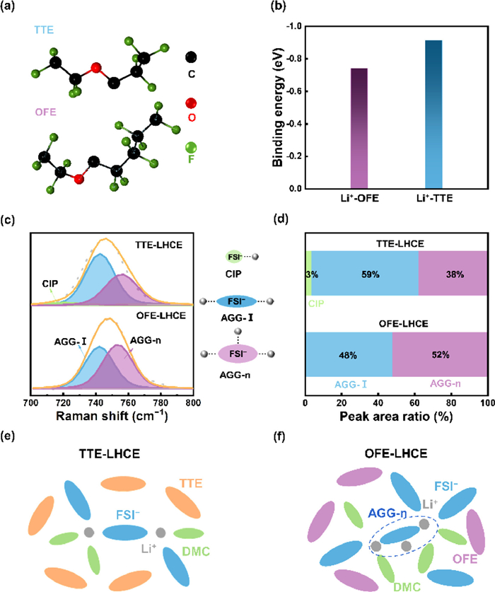
The solvating power of OFE and TTE and the solvation structure of OFE-based and TTE-based LHCE are investigated. 1H, 1H, 5H-Octafluoropentyl segment in OFE molecule has larger steric hindrance than 2,2,3,3-tetrafluoropropyl in TTE molecule (Fig. 1a). The large steric hindrance hinders the interaction between OFE and Li+ and enables OFE a decreased solvating power. Density functional theory (DFT) calculations were then performed to quantify the interaction between Li+ and TTE or OFE. The binding energy of Li+–OFE is lower than that of Li+–TTE (-0.74 vs. -0.91 eV, Fig. 1b), implying that OFE has a weaker solvating power than TTE. Thus, OFE is employed as the diluent in OFE-based LHCE (denoted as OFE-LHCE), which consists of lithium bis(fluorosulfonyl)imide (LiFSI), dimethyl carbonate (DMC), and OFE (1.0:1.5:2.0, by mol). The baseline electrolyte is composed of LiFSI, DMC, and TTE (1.0:1.5:2.0, by mol, denoted as TTE-LHCE). The solvation structure of OFE-LHCE and TTE-LHCE was disclosed by Raman spectra (Fig. 1c). The vibration band of FSI− at 710–780 cm−1 was deconvolved into CIP (717 cm−1), AGG-I (742 cm−1), and AGG-n (757 cm−1) [15]. CIP, AGG-I, and AGG-n refer to the Li+ solvation structure in which one FSI− interacts with one Li+, two Li+, and more than two Li+, respectively. The forms of Li+–FSI− interaction change significantly when using OFE. The proportion of CIP, AGG-I, and AGG-n in TTE-LHCE is 3%, 59% and 38%, respectively (Fig. 1d). In comparation, there is nearly no CIP in OFE-LHCE. The ratio of AGG-I decreases to 48% and the proportion of AGG-n increases to 52% in OFE-LHCE. Compared with the dominated AGG-I in TTE-LHCE (Fig. 1e), there are more AGG-n in OFE-LHCE where an anion coordinates with more than two Li+. Li+ further interact with other anions, thus forming a large solvation cluster (Fig. 1f).
Figure 1
Figure 1.
The solvation structure of OFE-LHCE and TTE-LHCE. (a) The molecular structure of TTE and OFE. (b) The binding energy of Li+-OFE and Li+-TTE interaction. (c) Raman spectra of OFE-LHCE and TTE-LHCE. (d) The peak area ratio of CIP, AGG-I, and AGG-n in TTE-LHCE and OFE-LHCE obtained from the fitting results of Raman spectra. The schematic diagram of solvation structure of Li ions in (e) TTE-LHCE and (f) OFE-LHCE.
The components in SEI were investigated by X-ray photoelectron spectroscopy (XPS, Fig. S1 in Supporting information). The F atomic content in SEI with OFE-LHCE is higher than that with TTE-LHCE during sputtering (5.88% vs. 3.53% and 7.54% vs. 4.95% at 0 and 60 s sputtering). LiF and the components with C–F bond were detected in the surface of SEI in OFE-LHCE and TTE-LHCE. However, the peak area ratio of LiF in OFE-LHCE is much higher than that in TTE-LHCE (85% vs. 68%). The higher content of LiF in SEI of OFE-LHCE is contributed by the increased ratio of AGG-n in electrolytes, which contributes to improving the uniformity of SEI.
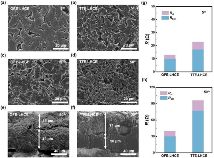
Li deposition uniformity was monitored to assess the uniformity of SEI. The capacity of deposited Li is 3.0 mAh/cm2. Compared with TTE-LHCE, the Li deposition morphology at the 5th cycle is denser in the battery with OFE-LHCE (Figs. 2a and b). Only 10 µm-thick inactive Li is formed and as much as 46 µm-thick active Li is maintained in OFE-LHCE, while a much thicker inactive Li layer of 23 µm and less active Li of 41 µm are observed in TTE-LHCE after 5 cycles (Fig. S2 in Supporting information). The superior Li deposition uniformity in OFE-LHCE is preserved after 50 cycles (Figs. 2c and d). There are much inactive Li and Li dendrites in TTE-LHCE after 50 cycles, while large chunks of Li deposits are dominated in OFE-LHCE. The thickness of inactive Li (35 µm) formed in OFE-LHCE after 50 cycles is much thinner than that in TTE-LHCE (74 µm) and the residual active Li in OFE-LHCE is more than that in TTE-LHCE (42 vs. 28 µm, Figs. 2e and f). Further, the morphology of Li metal anodes after battery capacity decays to 80% was also compared for understanding the failure of Li metal anodes. There is still seemingly deposited Li from the top-view of Li metal anodes after 200 cycles in OFE-LHCE. In contrast, powdered inactive Li covers the whole surface of Li metal anodes after 100 cycles in TTE-LHCE (Fig. S3 in Supporting information). The thickness of Li metal anodes after 200 cycles in OFE-LHCE is 167 µm, which is still thinner than that in TTE-LHCE (178 µm, Fig. S4 in Supporting information) only after 100 cycles. The increased ratio of AGG-n in OFE-LHCE results in improved uniformity Li deposition to effectively mitigate the formation of inactive Li.
Figure 2
Figure 2.
The Li deposition behaviors and internal resistance with TTE-LHCE and OFE-LHCE. Top and cross-sectional SEM images of Li metal anodes after Li plating obtained from the Li|NCM523 batteries at 0.4 C after 5 and 50 cycles in (a, c and e) OFE-LHCE and (b, d and f) TTE-LHCE. The evolution of interfacial resistance of Li|NCM523 batteries after (g) 5 cycles and (h) 50 cycles in TTE-LHCE and OFE-LHCE.
The behaviors of Li deposition and inactive Li accumulation influence the internal resistance of batteries. The resistance evolution of Li|NCM523 batteries with OFE-LHCE and TTE-LHCE was tested by electrochemical impedance spectroscopy (EIS, Figs. S5 and S6 in Supporting information). The semicircles at high and medium frequency are assigned to the resistance of Li+ transport through SEI (RSEI) and charge transfer (Rct), respectively [44]. RSEI and Rct of the battery with OFE-LHCE are 10 and 3 Ω after 5 cycles, respectively, which are smaller than that of TTE-LHCE (17 Ω for RSEI and 5 Ω for Rct, Fig. 2g). After 50 cycles, RSEI and Rct of the battery with the OFE-LHCE are 30 and 10 Ω, respectively, which are also much smaller than that of TTE-LHCE (77 Ω for RSEI and 20 Ω for Rct, Fig. 2h). When capacity decreases to 80%, RSEI and Rct in OFE-LHCE after 200 cycles increase to 75 and 15 Ω, respectively, while RSEI and Rct in TTE-LHCE after 100 cycles increases to 145 and 30 Ω, respectively (Fig. S7 in Supporting information). Therefore, the internal resistance of batteries with OFE-LHCE is notably mitigated for prolonging cycle life.
The performance of OFE-LHCE in stabilizing Li metal anodes was evaluated in Li|Li and Li|Cu cells with ultrathin Li metal anodes of 50 µm. The polarization voltage of Li|Li cells with OFE-LHCE maintains stable at 90 mV after 280 h but that with TTE-LHCE increases to 190 mV only after 100 h at 1.0 mA/cm2 and 3.0 mAh/cm2 (Fig. S8 in Supporting information). The CE of Li|Cu cells with OFE-LHCE maintains stable during 225 cycles at a current density of 1.0 mA/cm2 and capacity of 1.0 mAh/cm2, while that of TTE-LHCE rapidly decays after 150 cycles (Fig. S9a in Supporting information). The polarization voltage of Li|Cu cells with OFE-LHCE is smaller than that of TTE-LHCE (120 vs. 180 mV) after 50 cycles (Fig. S9b in Supporting information). The superior stability of Li|Li and Li|Cu cells with OFE-LHCE implies that OFE-LHCE can effectively improve the utilization efficiency of Li plating/stripping.
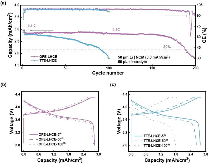
Li|LiNi0.5Co0.2Mn0.3O2 (NCM523) batteries under demanding conditions, including an ultrathin Li anode (50 µm), a high-loading NCM523 cathode (3.0 mAh/cm2), and lean electrolyte (50 µL), were further employed to evaluate the performance of OFE-LHCE. Li|NCM523 batteries were tested at 0.4 C after two cycles at 0.1 C for activation. Li|NCM523 batteries with TTE-LHCE only operate 90 cycles with a capacity retention of 80%. In contrast, Li|NCM523 batteries with OFE-LHCE undergo 190 cycles with a capacity retention of 80% (Fig. 3a). The results are well reproduced (Fig. S10 in Supporting information). Li|NCM523 batteries with OFE-LHCE deliver a small polarization voltage within 100 cycles (Fig. 3b). However, the polarization voltage dramatically increases after 50 cycles of the batteries with TTE-LHCE (Fig. 3c). Therefore, OFE-LHCE significantly prolongs the cycling lifespan of practical Li|NCM523 batteries.
Figure 3
Figure 3.
Electrochemical performance of Li|NCM523 batteries with different electrolytes. (a) Cycling performance at 0.4 C after two formation cycles at 0.1 C. The red dash line indicates 80% capacity retention of the initial discharge capacity at 0.4 C. Corresponding voltage profiles at the 5th, 50th, and 100th cycle in (b) TTE-LHCE and (c) OFE-LHCE.
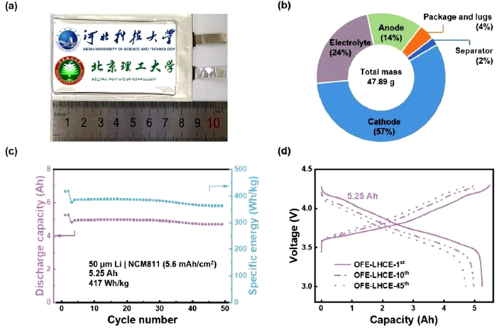
The application potential of OFE-LHCE in practical Li metal batteries was evaluated in a 5 Ah-level Li|NCM pouch cell (Fig. 4a). Ultrathin Li metal anodes (50 µm) and high-loading LiNi0.8Co0.1Mn0.1O2 (NCM811) cathodes (5.6 mAh/cm2) were employed. The size of the electrodes is 7.0 × 4.0 cm2. The active materials are double-layer coated on the current collectors. The total mass of the pouch cell (including all components of a pouch cell) is 47.89 g. Thereinto, the mass ratio of cathodes, electrolyte, anodes, package and lugs, and separator is 57%, 24%, 14%, 4% and 2%, respectively (Fig. 4b and Table S1 in Supporting information). The initial energy density of the pouch cell is 417 Wh/kg based on the total mass of the pouch cell, which is higher than the energy density ceiling of the current state-of-the-art Li-ion batteries. The Li|NCM811 pouch cell with OFE-LHCE stably operates 49 cycles with a capacity retention of 87% (Fig. 4c). The voltage polarization maintains stable during the cycles (Fig. 4d). The performance of OFE-LHCE in pouch cells demonstrates the potential of OFE-LHCE for practical Li metal batteries.
Figure 4
Figure 4.
Parameter information and electrochemical performance of Li|NCM811 pouch cell with OFE-LHCE. (a) Optical image of Li|NCM811 pouch cell. (b) The weight distribution of each component in the pouch cell. (c) Cycling performance of the Li|NCM811 pouch cell and (d) corresponding voltage profiles at the 1st, 10th, and 45th cycles in OFE-LHCE.
In conclusion, OFE with weakened solvating power is proposed as a diluent to regulate the solvation structure of Li+ in LHCE and improve the performance of LHCE. The weakened solvating power of OFE originates from its large steric effects. The proportion of AGG-n in OFE-LHCE increases to 52% compared with 38% in TTE-LHCE, which intensifies the formation of anion-derived SEI to improve the uniformity of Li deposition and alleviate inactive Li accumulation. Under demanding conditions including ultrathin Li anodes (50 µm) and high-loading cathodes (3.0 mAh/cm2), Li|NCM523 batteries with OFE-LHCE deliver a superior lifespan of 190 cycles based on 80% capacity retention compared with 90 cycles of TTE-LHCE. Furthermore, a pouch cell (5.25 Ah) with OFE-LHCE delivers a high initial specific energy of 417 Wh/kg and stably operates 49 cycles. This work provides an effective strategy to improve the performance of LHCE by weakening the solvation power of diluents and inspires further solvation structure regulation for long-cycling Li metal batteries.
Declaration of competing interest
The authors declare that they have no known competing financial interests or personal relationships that could have appeared to influence the work reported in this paper.
Acknowledgments
This work was supported by National Key Research and Development Program (Nos. 2021YFB2500300 and 2021YFB2400300), Beijing Natural Science Foundation (No. JQ20004), S&T Program of Hebei (No. 22344402D), National Natural Science Foundation of China (Nos. 22209010 and 22109007), China Postdoctoral Science Foundation (No. 2021M700404) and Beijing Institute of Technology Research Fund Program for Young Scholars.
Supplementary materials
Supplementary material associated with this article can be found, in the online version, at doi:10.1016/j.cclet.2023.108570.
Q.K. Zhang, X.Q. Zhang, L.P. Hou, et al., Adv. Energy Mater. 12 (2022) 2200139. doi: 10.1002/aenm.202200139
Figure 1
The solvation structure of OFE-LHCE and TTE-LHCE. (a) The molecular structure of TTE and OFE. (b) The binding energy of Li+-OFE and Li+-TTE interaction. (c) Raman spectra of OFE-LHCE and TTE-LHCE. (d) The peak area ratio of CIP, AGG-I, and AGG-n in TTE-LHCE and OFE-LHCE obtained from the fitting results of Raman spectra. The schematic diagram of solvation structure of Li ions in (e) TTE-LHCE and (f) OFE-LHCE.
Figure 2
The Li deposition behaviors and internal resistance with TTE-LHCE and OFE-LHCE. Top and cross-sectional SEM images of Li metal anodes after Li plating obtained from the Li|NCM523 batteries at 0.4 C after 5 and 50 cycles in (a, c and e) OFE-LHCE and (b, d and f) TTE-LHCE. The evolution of interfacial resistance of Li|NCM523 batteries after (g) 5 cycles and (h) 50 cycles in TTE-LHCE and OFE-LHCE.
Figure 3
Electrochemical performance of Li|NCM523 batteries with different electrolytes. (a) Cycling performance at 0.4 C after two formation cycles at 0.1 C. The red dash line indicates 80% capacity retention of the initial discharge capacity at 0.4 C. Corresponding voltage profiles at the 5th, 50th, and 100th cycle in (b) TTE-LHCE and (c) OFE-LHCE.
Figure 4
Parameter information and electrochemical performance of Li|NCM811 pouch cell with OFE-LHCE. (a) Optical image of Li|NCM811 pouch cell. (b) The weight distribution of each component in the pouch cell. (c) Cycling performance of the Li|NCM811 pouch cell and (d) corresponding voltage profiles at the 1st, 10th, and 45th cycles in OFE-LHCE.

 DownLoad:

 下载:
下载:


 下载:
下载:
