School of Chemistry and Chemical Engineering, Huazhong University of Science and Technology, Wuhan 430074, China
b.
State Key Laboratory of Advanced Electromagnetic Engineering and Technology, School of Electrical and Electronic Engineering, Huazhong University of Science and Technology, Wuhan 430074, China
c.
School of Materials and Energy, University of Electronic Science and Technology of China, Chengdu 611731, China
cyu2020@hust.edu.cn (C. Yu). 1 These authors contributed equally to this work.
Received Date:
04 May 2023 Accepted Date:
19 June 2023 Revised Date:
26 May 2023 Available Online:
15 June 2024
Abstract:
FeS2 shows significant potential as cathode material for all-solid-state lithium batteries (ASSLBs) due to its high theoretical specific capacity, low cost, and environmental friendliness. However, the poor ion/electron conductivity and large volume variation effect of FeS2 inhibit its practical applications. Here, the influence of particle size of FeS2 on the corresponding sulfide-based solid-state batteries is carefully investigated by tuning FeS2 size. Moreover, low operating temperature is chosen to mitigate the large volume changes during cycling in the battery. S-FeS2 with smaller particle sizes delivers superior electrochemical performances than that of the larger L-FeS2 in Li5.5PS4.5Cl1.5-based ASSLBs under different operating temperatures. S-FeS2 shows stable discharge capacities during 50 cycles with a current density of 0.1 mA/cm2 under -20 ℃. When the current density rises to 1.0 mA/cm2, it delivers an initial discharge capacity of 146.9 mAh/g and maintains 63% of the capacity after 100 cycles. This work contributes to constructing ASSLBs enables excellent electrochemical performances under extreme operating temperatures.
Lithium-ion batteries (LIBs) are widely used in portable electronic devices, electric vehicles, and renewable energy systems due to their high energy density and long cycle life [1,2]. However, the use of liquid electrolytes in conventional LIBs can lead to safety hazards and a limited operating temperature range. All-solid-state lithium-ion batteries (ASSLBs) constructed with solid electrolytes have emerged as a promising alternative, offering improved safety, higher energy density, and wider temperature stability [3,4]. Among many inorganic solid electrolytes [5–8], sulfide solid electrolytes have emerged as a promising option for use in energy storage devices due to their high ionic conductivity, good mechanical stability, and lower grain boundary impedance [9–11]. To realize the full potential of ASSLBs, it is crucial to develop high-performance electrode materials [12–15]. Among them, iron disulfide (FeS2) has recently attracted significant attention as a potential cathode material due to its high theoretical specific capacity (894 mAh/g), low cost, and environmental friendliness [16]. FeS2 has a layered structure with intercalation sites that can accommodate lithium ions, enabling it to function as a cathode material in ASSLBs [17,18]. FeS2 has been extensively investigated as a cathode material in liquid electrolyte-based LIBs, but its application in ASSLBs is still in its infancy [19]. One of the major challenges is the poor ionic and electronic conductivity of FeS2, leading to low rate capability and capacity fading during cycling [20]. In addition, FeS2 is known to undergo phase transitions upon lithium insertion and extraction, resulting in large volume changes and mechanical instability, which can cause electrode pulverization and capacity decay [21,22].
To overcome these challenges, researchers have developed several strategies to improve the electrochemical performance and cycling stability of FeS2. One approach is to reduce the particle size of FeS2, which can reduce the volume change and improve the intercalation/deintercalation kinetics of lithium ions [23]. Another strategy is to introduce dopants such as nitrogen [24], sulfur [25], and carbon [26] into the FeS2 lattice to enhance its electronic conductivity and stabilize the electrode structure during cycling. Additionally, researchers have explored the use of protective coatings and composites to further improve the stability and performance of FeS2 [27,28]. Among these strategies, reducing the particle size of FeS2 is the most economical and simple means, paving the way for the practical application of FeS2 in high-performance solid-state lithium-ion batteries.
The temperature has a significant impact on the performance and safety of ASSLBs. At low temperatures, the mobility of lithium ions in the solid electrolyte is reduced, leading to a decrease in the battery capacity and rate capability [29]. On the other hand, at high temperatures, the solid electrolyte can become unstable and decompose, leading to a loss of capacity and safety issues [30]. Additionally, the kinetics of the electrochemical reactions at the electrode/electrolyte interface is also affected by the temperature, which can further affect the battery performance. However, the effect of FeS2 size effect on the performance of all-solid-state batteries at different temperatures is not clear, and it is necessary to systematically study it.
In this work, we constructed an all-solid-state lithium-ion battery using Li5.5PS4.5Cl1.5 solid electrolyte, FeS2 cathode, and Li-In anode. We systematically investigated the effects of FeS2 particle size and temperature on the electrochemical performance of ASSLBs assembled with FeS2 cathode. In-situ stack pressure measurement, in-situ electrochemical impedance spectroscopy (EIS), and ex-situ X-ray diffraction (XRD) were used to monitor the stress change, resistance evolution, and phase transition process of solid-state batteries at various operating temperatures. Additionally, we verified the possible mechanism using scanning electron microscopy (SEM) and X-ray photoelectron spectroscopy (XPS). The effects of size and temperature were revealed, indicating that small size FeS2 and low ambient temperature can alleviate the volume effect during the cycle and the effect of side reactions at the electrode/electrolyte interface on battery performance. Combined with the reduction of FeS2 particle size effect and low-temperature operation, we achieved a longer stable cycle of all-solid-state batteries.
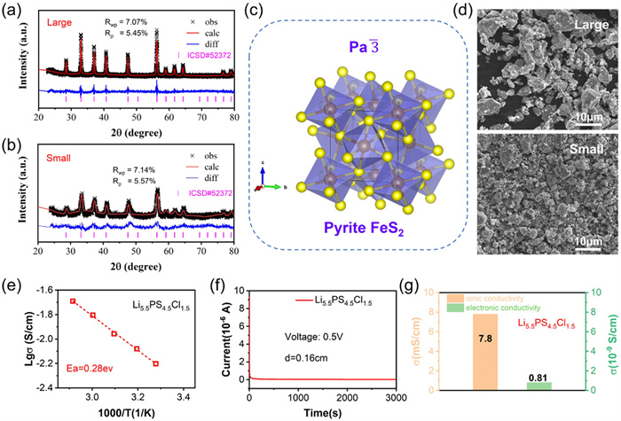
To prepare the FeS2 material with smaller particle sizes, the starting FeS2 (L-FeS2) was milled using a high-rotation speed of 550 rpm for 20 h to obtain the target FeS2, which was named S-FeS2. Powder XRD was performed on both the L-FeS2 and S-FeS2 electrode materials. XRD refinements of both samples confirm that these obtained FeS2 possess the cubic symmetry structure with a space group of Pa3_ (Figs. 1a–c) [31]. The SEM image results in Fig. 1d confirm that L-FeS2 shows a larger particle size than S-FeS2. In addition, we have further confirmed that S-FeS2 possesses a smaller particle size by means of particle size distribution tests (Fig. S1 in Supoprting information). As we know, solid electrolytes play a crucial role in the battery performances of all-solid-state batteries [32]. To evaluate the electrochemical performance of these FeS2 materials in the battery, the chlorine-rich argyrodite electrolyte Li5.5PS4.5Cl1.5 with ultrahigh Li-ion conductivity and good chemical/electrochemical stabilities was chosen and synthesized using the typical mechanochemical synthesis route as reported in our previous works [33–37]. The ionic conductivity of the prepared electrolyte was characterized using the AC impedance method on a symmetric cell with stainless steel as the blocking electrode. The complex impedance plots measured at different temperatures are shown in Fig. S2 (Supoprting information). The prepared Li5.5PS4.5Cl1.5 electrolyte shows a high Li-ion conductivity up to 7.8 mS/cm at room temperature with a low activation energy of 0.28 eV deduced from the Arrhenius plots of Li-ion conductivities measured at various temperatures (Fig. 1e). Moreover, the electronic conductivity of the prepared Li5.5PS4.5Cl1.5 materials was also tested via the DC polarization method. An ultralow electronic conductivity of 8.1× 10⁻¹⁰ S/cm is obtained based on the DC plots shown in Fig. 1f. Based on the above results from the AC impedance and DC plot results, it can be concluded that the synthesized Li5.5PS4.5Cl1.5 is a superior solid electrolyte for solid-state batteries due to the ultrahigh ionic conductivity and low electronic conductivity (Fig. 1g).
Figure 1
Figure 1.
(a) XRD refinements of the prepared (a) S- and (b) L-FeS2 materials. (c) Crystal structure of the FeS2 material. (d) SEM images of the S- and L-FeS2 materials. (e) Temperature-dependent Li-ion conductivities and (f) the DC polarization plot of the synthesized Li5.5PS4.5Cl1.5 solid electrolyte. (g) Li-ion conductivities at these chosen temperatures and the room temperature electronic conductivity of the Li5.5PS4.5Cl1.5 solid electrolyte.
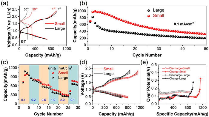
All-solid-state lithium batteries consisting of the Li5.5PS4.5Cl1.5 electrolyte combined with the S/L-FeS2 cathode and Li-In anode were fabricated and cycled at various current densities between 0.4 V and 2.4 V (vs. Li-In) to investigate the electrochemical performances. Fig. 2a shows the charge/discharge profiles for the 1st and 50th cycles of the corresponding solid-state batteries using L-FeS2 and S-FeS2 materials as cathode cycled at 0.1 mA/cm2 at room temperature. During the initial discharge process, both batteries show clear discharge plateaus at ~0.8 V (vs. Li-In). Moreover, the L-FeS2 and S-FeS2 cathodes deliver discharge capacities of 686.3 and 703.9 mAh/g for the 1st cycle, respectively. During the following initial charge progress, two charge plateaus located at ~1.2 and ~1.8 V (vs. Li-In) are observed in the charging profiles. These two voltage plateaus are associated with the electrochemical reaction between Fe and Li2S and the oxidation reaction of the remaining Li2S to S, respectively. For both L- and S-FeS2 electrodes, the discharge capacity is much higher than the charge capacity during the 1st cycle, which may be related to the decomposition of sulfide electrolyte during charge/discharge processes. As shown in Fig. 2b, both L- and S-FeS2 cathodes show a fast drop in discharge capacities during 50 cycles. As a typical conversion electrode material, FeS2 suffers fast capacity degradation during cycling due to the large volume expansion in lithium batteries using liquid organic electrolytes [38]. For all-solid-state batteries using FeS2 electrode materials and solid electrolytes, this situation becomes even worse due to the poor solid-solid contact and more intense volume variations during cycling in the battery [35,39]. However, the S-FeS2 cathode still delivers much higher discharge capacities compared to the L-FeS2 cathode, suggesting that lowering the particle size of the FeS2 electrode material is helpful to achieve higher capacities. Fig. S3 (Supporting information) shows the SEM images of the surface section of the cathode mixture part of the assembled S-FeS2/Li5.5PS4.5Cl1.5/Li-In and L-FeS2/Li5.5PS4.5Cl1.5/Li-In batteries. The cathode mixture with S-FeS2 shows superior solid-solid contact than that of the L-FeS2. For the S-FeS2/Li5.5PS4.5Cl1.5 cathode mixture, intimate contact between different particles is observed, while clear cracks and voids are detected in the SEM image of the L-FeS2/Li5.5PS4.5Cl1.5 cathode mixture. The good solid-solid interface contact produces fast Li-ion transport with small interfacial resistance, while poor solid-solid interface contact lowers Li-ion mobility and yields huge interfacial resistances. Therefore, the S-FeS2 electrode delivers higher discharge capacities and slightly better cyclability than that the L-FeS2 electrode at room temperature. Furthermore, the rate capability of both batteries was also verified at different charge/discharge current densities. As shown in Fig. 2c, the discharge capacity of the L-FeS2/Li5.5PS4.5Cl1.5/Li-In battery was 950.7 mAh/g at 0.1 mA/cm2, 729.9 mAh/g at 0.2 mA/cm2, 538.1 mAh/g at 0.5 mA/cm2, 346.8 mAh/g at 1.0 mA/cm2 and 244.7 mAh/g at 2.0 mA/cm2, respectively. In contrast, the S-FeS2/Li5.5PS4.5Cl1.5/Li-In battery delivers discharge capacities of 950.9 mAh/g at 0.1 mA/cm2, 787.0 mAh/g at 0.2 mA/cm2, 622.7 mAh/g at 0.5 mA/cm2, 434.4 mAh/g at 1.0 mA/cm2, and 288.0 mAh/g at 2.0 mA/cm2, respectively. S-FeS2 electrode delivers much higher discharge capacities than that of the L-FeS2 at higher charge/discharge current densities. FeS2 materials with smaller particle sizes mean short diffusion lengths, resulting in better electrochemical performances, especially at large current densities. Moreover, superior battery performance is also associated with solid/solid interfacial diffusions. To investigate the Li-ion dynamics in the L- and S-FeS2 cathode mixture, GITT was performed on both L-FeS2/Li5.5PS4.5Cl1.5/Li-In and S-FeS2/Li5.5PS4.5Cl1.5/Li-In batteries at room temperature. As shown in Figs. 2d and e, S-FeS2 shows smaller overpotentials and faster Li-ion diffusion rates than that L-FeS2 at different charge/discharge states, which agrees well with the previous analysis.
Figure 2
Figure 2.
(a) The charge/discharge curves of the 1st and 50th cycles for the assembled FeS2/ Li5.5PS4.5Cl1.5/Li-In all-solid-state batteries using the obtained S- and L-FeS2 materials as the cathodes when cycled at 0.1 mA/cm2. (b) The corresponding cycling performances when these batteries were first cycled at the charge/discharge current density of 0.1 mA/cm2. (c) The rate capability of the above batteries. (d) GITT plots, and (e) charge and discharge polarization voltages during the initial cycle. All those measurements are performed at room temperature and charged/discharged between 0.4 V and 2.4 V (vs. Li-In).
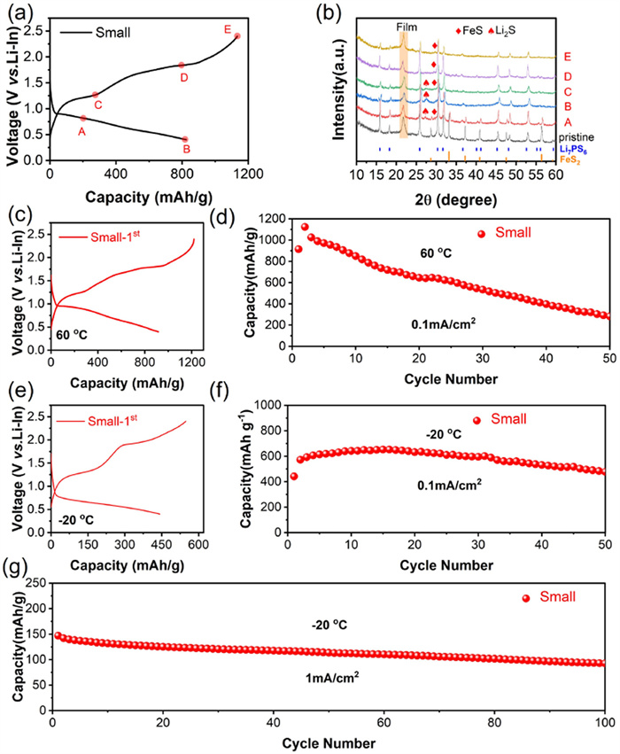
To reveal the phase variations during the initial charge/discharge process of the assembled S-FeS2/Li5.5PS4.5Cl1.5/Li-In cell, ex-situ X-ray diffraction (XRD) was performed on the fresh cathode mixture and cycled cathode at different charge /discharge states. As shown in Figs. 3a and b, due to the existence of Li5.5PS4.5Cl1.5 with good crystallization in the mixture, the diffraction peaks assigned to these products produced by the FeS2 during cycling are weak. For the fresh cathode mixture before cycling, the major diffraction peaks are indexed to the pure argyrodite and FeS2 phases. During the discharge process, diffraction peaks due to the FeS and Li2S phases are detected in the pattern of point A, indicating that these two materials have been formed at the state of point A. These phases were formed due to the reaction between the active FeS2 phase and mobile Li+. The decreased diffraction peaks belonging to the FeS2 phase suggest a lowered amount of FeS2 phase in the mixture, which is in good agreement with the above analysis. The related reaction is as follows: FeS2 + 2Li+ + 2e− → FeS + Li2S. During the following discharge process from point A to point B, the intensity of XRD peaks attributed to FeS2 gradually decreases, while the diffraction peaks assigned to the Li2S phase become stronger. This conversion reaction is attributed to the translation of FeS2 to Li2S and FeS, and further to the Fe. The related electrochemical reaction is FeS + 2Li+ + 2e− → Li2S + Fe. It should be mentioned that no signal indexed to the pure Fe is detected in the XRD pattern. Previous studies have found that a spontaneous reaction between the Fe and FeS2 occurs during cycling, leading to the formation of the FeS phase in the mixture. Some of the FeS phase formed during the charge/discharge process adopts an amorphous phase structure, which makes it difficult to be detected using the typical powder XRD characterization method [38]. In the subsequent initial charging process, more and more diffraction peaks attributed to the Li2S and FeS phases appear in the XRD pattern of point C. The related electrochemical reaction is mainly described as Li2S + Fe → FeS + 2Li+ + 2e−. This process is associated with the transition reaction from Li2S/Fe to the FeS phase. When the charging voltage reaches point D or an even higher voltage of point E (2.4 V vs. Li-In), an oxidation reaction from the Li2S phase to the S occurs as follows: Li2S → S + 2Li+ + 2e−, resulting in decreased Li2S phase and increased S in the cathode mixture. When the voltage reaches the upper cut-off voltage of point E, almost all Li2S in the cathode mixture has been successfully converted to the amorphous S, Sx, and FeS phases.
Figure 3
Figure 3.
(a) The first charge and discharge profiles of the S-FeS2/Li5.5PS4.5Cl1.5/Li-In battery and (b) ex-situ XRD patterns of the cycled cathode mixtures at different cut-off voltages. The battery was cycled at 0.1 mA/cm2 between 0.4 V and 2.4 V (vs. Li-In). The initial charge/discharge plots of the S-FeS2/Li5.5PS4.5Cl1.5/Li-In all-solid-state batteries when cycled under the current density of 0.1 mA/cm2 between 0.4 V and 2.4 V (vs. Li-In) at different operating temperatures, (c) 60 ℃ and (e) -20 ℃, respectively. The corresponding cycling performances at (d) 60 ℃ and (f) -20 ℃. (g) The long cycling performance of this battery cycled at a larger charge/discharge current density of 1.0 mA/cm2 between 0.4 V and 2.4 V (vs. Li-In) at -20 ℃.
In addition, electrochemical performances of the assembled S-FeS2/Li5.5PS4.5Cl1.5/Li-In battery operated at different temperatures were also investigated. To evaluate the battery performance at elevated temperatures, it was charged/discharged at the same current density of 0.1 mA/cm2 under 60 ℃. As depicted in Fig. 3c, it shows similar charge/discharge plateaus for the 1st cycle as worked at room temperature. It delivers a high initial discharge capacity of 914.3 mAh/g and maintains 282.1 mAh/g after 50 cycles (Fig. 3d). Although it shows a much higher initial discharge capacity than that at room temperature, it suffers much faster discharge capacity degradations during the same cycling numbers. This may be associated with intense volume changes during cycling at elevated temperatures. When the operating temperature lowers to -20 ℃, similar charge/discharge curves are observed for the 1st cycle, as displayed in Fig. 3e, suggesting that the S-FeS2 electrode undergoes the same electrochemical reaction at different operating temperatures. Due to the slow Li-ion transport rate under low temperatures, it delivers much lower capacities than that at room and elevated temperatures under the same testing condition (Fig. 3f). Interestingly, it exhibits much more stable cycling performance at low temperatures compared to the higher temperature. After 50 cycles, it still can deliver a high discharge capacity of 477.5 mAh/g when cycled at 0.1 mA/cm2 under -20 ℃. Besides, this assembled battery also can cycle even under an ultrahigh current density of 1.0 mA/cm2. It delivers an initial discharge capacity of 146.9 mAh/g and sustains a discharge capacity of 92.6 mAh/g after 100 cycles (Fig. 3g). Plenty of research has reported that sulfide electrode suffers large volume changes in lithium batteries using liquid electrolytes, yielding a fast decrease in capacity and poor cycling performance. In our case in this work, FeS2 also shows poor cyclability when combined with Li5.5PS4.5Cl1.5 electrolyte in a solid-state battery cycled at room temperature (Fig. 2b). The huge volume variations during cycling degrade the effective contact between the FeS2 active material and the Li5.5PS4.5Cl1.5 electrolyte, which plays a key role in the corresponding battery performance. However, when the operating temperature lowers to ultralow temperatures, such as -20 ℃, the shrinkage of different materials in the battery can mitigate the volume change and maintain good solid/solid interface contact between the active materials and the Li5.5PS4.5Cl1.5 electrolytes, resulting in superior cycling performance. To verify the differences of Li-ion diffusion in the cathode mixture of the assembled S-FeS2/Li5.5PS4.5Cl1.5/Li-In battery cycled at different operating temperatures, cyclic voltammetry (CV) with different scan rates were performed on the battery under. As illustrated in Figs. S4a-c (Supporting information), similar oxidation/reduction peaks are detected in the CV curves measured at both room temperature and 60 ℃, and no obvious significant peak is observed in the CV curve scanned at -20 ℃. As depicted in Figs. S4d and e (Supporting information), the ln(ip) values for the S-FeS2/Li5.5PS4.5Cl1.5/Li-In battery tested at 60 ℃ is significantly higher than that at room temperature, indicating that Li-ion diffusion rates in the S-FeS2/Li5.5PS4.5Cl1.5 cathode mixture are much higher at elevated temperatures. Consequently, this battery presents greater charge/discharge capacities at higher temperatures (Fig. 3).
To further evaluate the kinetics of the all-solid-state battery over a wide temperature range, Figs. S5a and b (Supporting information) show the impedance spectrum of the all-solid-state lithium battery during the first discharge/charge cycle at -20 ℃, room temperature, and 60 ℃, respectively. It can be seen that the resistance gradually increases during discharge at room temperature. The gradual increase in resistance during discharge arises from the volume expansion of the active material in the cathode composite. No significant change is observed in the early stages of the charging process, and in the later stages, nearing the fully charged state, the increase in impedance is more due to the charge transfer impedance of the cell in the higher charge state, which in agreement with the literature reported earlier. At 60 ℃, the pattern of change is essentially the same, however, its total impedance is significantly lower, mainly due to the increased external temperature, which accelerates the ion migration rate and enhances the ion diffusion kinetics. Notably, its impedance is significantly higher at low temperatures, but its impedance during both discharge/charge remains stable and unchanged, suggesting that while low temperatures reduce lithium ion migration kinetics, they simultaneously enhance its stability during cycling. To further determine how the impedance changes during charging/discharging, a semi-quantitative relaxation time distribution (DRT) method was used to further analyze the impedance spectrum. Several major peaks appear in the DRT results (Fig. S5c in Supporting information), which each have a corresponding electrochemical reaction process, as reported in the previous literature [40,41]. At room temperature, during the discharge process, peaks with time constants between 10−2–10−1 s and 10−2–10−1 s correspond to ion transport processes at the anode and cathode interfaces, respectively. Peaks with time constants between 100–101 s have the largest FeS2 cathode related to the solid-state diffusion (charge transfer process). The ion transport processes at the anode and cathode interface are strongly influenced by the discharge state. By observing the trend, the change is towards a large impedance and an increasing time constant as the discharge proceeds. At 60 ℃, the trend is essentially the same, while on the contrary, there is a large difference at low temperatures, where on the one hand the time constants peak around 10−7 s and 10−6 s respectively, which are mainly related to the bulk phase and grain boundary ion transport of the electrolyte, indicating that there is a significant overall decrease in ion migration kinetics at high temperatures, and on the other hand, the impedance of ions at the cathode/anode interface does not change much, proving that low temperatures ensure the ion charge/discharge process is stable at low temperatures.
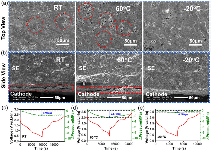
To further confirm the above hypothesis, the surface and cross-section of the cathode mixture of the S-FeS2/Li5.5PS4.5Cl1.5/Li-In battery cycled at various operating temperatures after 50 cycles were characterized using ex-situ SEM. As shown in Fig. 4a, for the cathode mixtures operated at room temperature and 60 ℃, clear cracks and voids (depicted by red dashed circles) are observed in the SEM images, while in contrast, a much dense surface is detected for the cathode cycled under -20 ℃ after 50 cycles. This suggests that the volume variations of the cathode section of the assembled S-FeS2/Li5.5PS4.5Cl1.5/Li-In battery increase as a function of operating temperatures. Moreover, obvious gaps are observed between the cathode mixture layer and the solid electrolyte layer in the SEM images of these bilayer pellets after 50 cycles at room temperature and 60 ℃ (Fig. 4b), indicating that huge volume changes occur in the battery when cycled at those temperatures. In comparison, no clear cracks or gaps can be detected from the SEM image of the cross-section of the battery cycled at -20 ℃ after 50 cycles, suggesting excellent solid-solid contact between the cathode mixture layer and solid electrolyte layer during cycling under this low operating temperature. This validates the superior cycling performances of the assembled S-FeS2/Li5.5PS4.5Cl1.5/Li-In battery working at -20 ℃. While the poor cycling performance and fast degradation of capacities of the battery operated at room and elevated temperatures are attributed to the cracks and gaps formed in the cathode mixture and the cathode layer/solid electrolyte layer interface during cycling, which results in bad solid/solid interface contact and Li-ion diffusion behavior with high resistances. Of course, in order to prevent temperature effects from causing such changes in the internal structure of the battery, SEM images of uncycled batteries at different temperatures were tested under the same conditions and it can be seen that external temperature changes alone have almost no effect on the internal structure of the battery, further confirming that temperature changes mainly affect the change in volume of the electrode material during cycling and thus lead to changes in the internal solid-solid contact of the battery (Fig. S6 in Supporting information). Furthermore, in solid-state batteries, the volume expansion of electrode material will lead to significant stress caused by local microstructure changes in the battery [42], in-situ stacking pressure measurements were chosen to investigate inner pressure variations of the assembled S-FeS2/Li5.5PS4.5Cl1.5/Li-In cells cycled at different operating temperatures. As shown in Figs. 4c–e, the stacking pressure decreases during the initial discharge process and increases during the subsequent charging process. Larger stress changes in the battery when it was cycled at room temperature and 60 ℃, yielding degraded solid/solid interface contact of the electrolyte layer and poorer electrochemical performance. In contrast, smaller stress changes are detected when the battery worked at -20 ℃, maintaining good solid/solid interface contact and ensuring good cycling stability, which is consistent well with previous SEM and battery performance results.
Figure 4
Figure 4.
SEM images of the (a) surface section and (b) cross-section for the cycled cathode mixtures of the S-FeS2/ Li5.5PS4.5Cl1.5/Li-In battery cycled at different operating temperatures. In-situ pressure variations of the S-FeS2/Li5.5PS4.5Cl1.5/Li-In all-solid-state battery cycled under the current density of 0.4 mA/cm2 between 0.4 V and 2.4 V (vs. Li-In) under different operating temperatures, (c) room temperature, (d) 60 ℃, and (e) -20 ℃, respectively.
Finally, X-ray photoelectron spectroscopy (XPS) was utilized to reveal the oxidization reactions of the cathode mixture before and after cycling at varying temperatures. As depicted in Fig. S7 (Supporting information), typical doublet peaks of S 2p and P 2p signals are observed in the S and P XPS spectra of the original Li5.5PS4.5Cl1.5 electrolyte, indicating the PS43- structure of the argyrodite [43]. For the cycled cathode mixture operated at room temperature, besides these above peaks, extra peaks assigned to the Li2S and P2Sx components are also detected in the S 2p and P 2p spectra [44], suggesting the redox effect of FeS2 active materials and the decomposition of Li5.5PS4.5Cl1.5 electrolyte during cycling. When the operating temperature rises to 60 ℃, a more severe redox scenario occurs, resulting in additional by-products, such as the transformation of PS43− structural components to Li2S and P2Sx. Therefore, the relative intensity of the S 2p and P 2p signals at elevated temperatures are much higher than that at room temperature, yielding more severe side reactions associated with sulfide electrolytes. Interestingly, when the operating temperature lowers to -20 ℃, almost no S 2p and P 2p signals belonging to the Li2S and P2Sx phases are observed in the cycled cathode mixture. Only the same S 2p and P 2p signals are detected in the spectra at this temperature compared to that at room temperature, suggesting the cycled cathode mixture contains PS43− and few other redox by-products are detected. It seems that the lower operating temperature is helpful to mitigate the side reaction associated with the Li5.5PS4.5Cl1.5 electrolyte. These XPS analysis results agree well with the previous electrochemical performances.
In summary, FeS2 powder with large and small particle sizes was prepared via the mechanical milling route and was applied as active materials in ASSLBs combined with Li5.5PS4.5Cl1.5 electrolytes and Li-In anode to investigate the battery performances under different operating temperatures. It seems that the electrochemical performances of the above batteries are greatly related to the particle sizes. S-FeS2 shows higher discharge capacities, lower voltage polarization, better rate capability, and faster Li-ion kinetics than that of L-FeS2 at room temperature. Specifically, the S-FeS2 delivers a high initial discharge capacity of 703.9 mAh/g at 0.1 mA/cm2 and sustains much higher capacities during the subsequent 50 cycles than that of L-FeS2. Moreover, the assembled S-FeS2/Li5.5PS4.5Cl1.5/Li-In cell delivers a high discharge capacity of 914.3 mAh/g when the operating temperature rises to 60 ℃ due to the enhanced Li-ion migration at elevated temperatures. However, it suffers fast capacity degradation due to the significant volume expansion at this temperature in the following charge/discharge cycles. Interestingly, when the operating temperature lowers to -20 ℃, this battery can still deliver a high discharge capacity of 441.8 mAh/g at 0.1 mA/cm2 and exhibit stable cyclability in the next 50 cycles. At an ultrahigh current density of 1.0 mA/cm2, the battery shows large discharge capacities and excellent cycling performance during 100 cycles. Multiple characterization methods, including in-situ EIS, stacking pressure tests, ex-situ SEM, ex-situ TEM, and ex-situ XPS were combined to unravel the working mechanism of the S-FeS2 electrode cycled at different operating temperatures. The electrochemical performance differences of S-FeS2/Li5.5PS4.5Cl1.5/Li-In battery are highly dependent on the solid-solid interfacial contact in the battery under different ambient temperatures. This battery suffers smaller volume changes at lower temperatures than that under higher temperatures.
Declaration of competing interest
The authors declare no competing financial interest.
Acknowledgments
This work was supported by the National Key Research and Development Program (No. 2021YFB2400300) and the National Natural Science Foundation of China (No. 52177214). This work is also supported by China Fujian Energy Devices Science and Technology Innovation Laboratory Open Fund (No. 21C-OP202211). We gratefully acknowledge the Analytical and Testing Center of HUST for the technical support.
Supplementary materials
Supplementary material associated with this article can be found, in the online version, at doi:10.1016/j.cclet.2023.108717.
S.S. Shin, J.S. Kim, S. Choi, et al., Chem. Commun. 57 (2021) 3453–3456. doi: 10.1039/d0cc08367d
[42]
R. Koerver, W.B. Zhang, L. de Biasi, et al., Energ. Environ. Sci. 11 (2018) 2142–2158. doi: 10.1039/c8ee00907d
[43]
J. Auvergniot, A. Cassel, J.B. Ledeuil, et al., Chem. Mater. 29 (2017) 3883–3890. doi: 10.1021/acs.chemmater.6b04990
[44]
J. Auvergniot, A. Cassel, D. Foix, et al., Solid State Ionics 300 (2017) 78–85. doi: 10.1016/j.ssi.2016.11.029
Figure 1
(a) XRD refinements of the prepared (a) S- and (b) L-FeS2 materials. (c) Crystal structure of the FeS2 material. (d) SEM images of the S- and L-FeS2 materials. (e) Temperature-dependent Li-ion conductivities and (f) the DC polarization plot of the synthesized Li5.5PS4.5Cl1.5 solid electrolyte. (g) Li-ion conductivities at these chosen temperatures and the room temperature electronic conductivity of the Li5.5PS4.5Cl1.5 solid electrolyte.
Figure 2
(a) The charge/discharge curves of the 1st and 50th cycles for the assembled FeS2/ Li5.5PS4.5Cl1.5/Li-In all-solid-state batteries using the obtained S- and L-FeS2 materials as the cathodes when cycled at 0.1 mA/cm2. (b) The corresponding cycling performances when these batteries were first cycled at the charge/discharge current density of 0.1 mA/cm2. (c) The rate capability of the above batteries. (d) GITT plots, and (e) charge and discharge polarization voltages during the initial cycle. All those measurements are performed at room temperature and charged/discharged between 0.4 V and 2.4 V (vs. Li-In).
Figure 3
(a) The first charge and discharge profiles of the S-FeS2/Li5.5PS4.5Cl1.5/Li-In battery and (b) ex-situ XRD patterns of the cycled cathode mixtures at different cut-off voltages. The battery was cycled at 0.1 mA/cm2 between 0.4 V and 2.4 V (vs. Li-In). The initial charge/discharge plots of the S-FeS2/Li5.5PS4.5Cl1.5/Li-In all-solid-state batteries when cycled under the current density of 0.1 mA/cm2 between 0.4 V and 2.4 V (vs. Li-In) at different operating temperatures, (c) 60 ℃ and (e) -20 ℃, respectively. The corresponding cycling performances at (d) 60 ℃ and (f) -20 ℃. (g) The long cycling performance of this battery cycled at a larger charge/discharge current density of 1.0 mA/cm2 between 0.4 V and 2.4 V (vs. Li-In) at -20 ℃.
Figure 4
SEM images of the (a) surface section and (b) cross-section for the cycled cathode mixtures of the S-FeS2/ Li5.5PS4.5Cl1.5/Li-In battery cycled at different operating temperatures. In-situ pressure variations of the S-FeS2/Li5.5PS4.5Cl1.5/Li-In all-solid-state battery cycled under the current density of 0.4 mA/cm2 between 0.4 V and 2.4 V (vs. Li-In) under different operating temperatures, (c) room temperature, (d) 60 ℃, and (e) -20 ℃, respectively.

 DownLoad:

 下载:
下载:


