Table 1.
Experimental conditions and electrocatalytic performance of nickel phosphide samples
Citation:
XU Dan, ZHU Liang-Kui, ZHOU Dan, FU Yu-Rong, FU Xiao-Wen, CHEN Rong, LI Hai-Xia. Preparation of Metal-Organic Framework-Derived Nano-Scale Nickel Phosphide Catalysts[J]. Chinese Journal of Inorganic Chemistry,
2019, 35(8): 1455-1462.
doi:
10.11862/CJIC.2019.148

基于金属有机骨架前驱体制备纳米磷化镍催化剂
摘要:
采用镍基金属有机骨架化合物(Ni-MOF)为前驱体,通过低温碳化获得Ni@C,并通过磷化成功地制备了不同结构的磷化镍纳米颗粒。将所得材料应用于析氢反应(HER)催化剂,在Ni@C与红磷质量比为1:1及热解温度为500℃时获得的Ni1P1-500表现出优异的电催化性能,在酸性介质中,电流密度为10 mA·cm-2时,过电位为178 mV,并展现了良好的循环性能。较小的Tafel斜率(62 mV·dec-1)揭示了析氢反应的机理为Desorption-Heyrovsky机制。优异的电催化性能可归因于磷化镍催化剂表面存在的质子受体(P位点)和氢化物受体(Ni位点)活性中心。
English
Preparation of Metal-Organic Framework-Derived Nano-Scale Nickel Phosphide Catalysts
Abstract:
Herein, nickel phosphides nanoparticles with different phases were successfully prepared by multi-step calcination and phosphidation process at low temperature using Ni based MOF (Ni-MOF) as the precursor. The resulting materials were applied to the hydrogen evolution reaction (HER) catalyst, Ni1P1-500 obtained at a mass ratio of Ni@C to red phosphorus of 1:1 and a pyrolysis temperature of 500℃ exhibited a remarkably enhanced electrocatalytic performance with a current density of 10 mA·cm-2 at an overpotential of 178 mV and a superior durability for the HER in acid media. A small Tafel slope of 62 mV·dec-1 revealed a Desorption-Heyrovsky mechanism during the HER. The excellent electrocatalytic performance might be ascribed to the presence of the proton acceptor (P site) and hydride-acceptor (Ni site) centers on the surface of nickel phosphide.
-
0. Introduction
In the past few decades, the production of environmentally friendly energy has become a critical concern due to increasing environmental pollution and energy demand[1-3]. Hydrogen is considered to be one of the most ideal and cleanest energy sources[4]. It is considered to be the main energy carrier due to its high energy storage, ideal combustion efficiency and non-toxicity. Water electrolysis is an alternative process and a desirable way to produce molecular hydrogen, but both half-reactions of water splitting, namely, the oxygen evolution reaction (OER) and the hydrogen evolution reaction (HER), still remain technical challenges[5]. Although, platinum (Pt)-based materials are most active and stable catalysts for HER, but their prohibitive cost, scarce reserves, and poor durability significantly prohibit widespread application in energy conversion[6-7]. It is therefore highly imperative and challenging to develop non-precious metal electrocatalysts for HER to achieve efficient overall water splitting.
At present, metal phosphide (TMP) catalysts composed of transition elements such as Fe, Co, Ni and Mo are the alternative to precious metal catalysts and achieve high efficiency of HER catalytic activity[8-12]. In particular, nickel phosphides (Ni3P, Ni2P, Ni5P2, Ni12P5 and Ni5P4) of different phases exhibit promising HER catalytic performance in strongly acidic electrolytes. Schaak′s research group synthesized nanostructured Ni2P with a high accessible surface area and a high density of exposed (001) facets. The active Ni2P nanoparticles investigated for electrocatal-ytic activity and stability for the HER in acidic solutions, which had the highest HER activity among the non-noble metals at that time[13]. Dismukes′s group reported microcrystalline Ni3P as a non-precious metal electrocatalyst for hydrogen evolution reaction (HER), whose catalytic activity was second only to the activity of Pt[14].
Metal-organic frameworks (MOFs), with high porosity, large surface areas and inherent presence of heteroatoms have been proved to be ideal sacrificial templates for fabricating electrocatalyst by changing the thermal conditions in the different atmosphere[15-17]. Liu′s group prepared carbon-cobalt hybrid materials through the thermolysis of the Co-ZIF precursor at 750 ℃ which has been explored as a good catalyst for oxygen reduction reaction (ORR)[18]. Dong′s group prepared porous CoP concave polyhedrons (CoP CPHs) via low-temperature multi-step calcination using Co-MOF (ZIF-67) polyhedrons as the precursor[19]. The eletrocatalyst nanomaterials prepared by this novel MOF-templated route possessed many advantages such as large internal surface area, high crystallinity, tailorable porous structure and more catalytic centers. More and more researchers focuse on fabricating desired catalysts derived from MOFs precursors.
In this work, Ni-based metal-organic framework (Ni-MOF) as a precursor is used to carbonize and synthesize a nickel-carbon composite (Ni@C) under a nitrogen atmosphere at 500 ℃. Next, the nickel phos-phide nanocatalysts are obtained by phosphorization of Ni@C composite using phosphorus vapor without complicated chemical reactions and post-treatment steps involved. The MOF-derived crystalline Ni1P1-500 nanostructure guarantees the highly exposed active sites, and the charge properties of Ni and P contributes to a consecutive electrical conductivity, which is crucial for electron transfer. As a result, the Ni1P1-500 nanocatalyst exhibited excellent HER activity in acid solution with overpotentials of 178 mV at 10 mA·cm-2. More importantly, this facile two-step synthetic method reported here has the characteristics of simple synthesis and large-scale production, can be extended to other MOFs to synthesize metal phosphides.
1. Experimental
1.1 Synthesis
1.1.1 Synthesis of 1, 4, 5, 8-naphthalenetetracarboxylic acid (NTCA)
1, 4, 5, 8-Naphthalenetetracarboxylic dianhydride (NTCDA, 1 mmol) was dissolved in NaOH (2 mol·L-1, 50 mL) solution and stirred at 60~70 ℃. After hydrol-yzing for 1 h, the solution was cooled to room temp-erature, and 1 mol·L-1 HCl solution was added dropwise to adjust the pH value to 5~6. Then the precipitate was filtered and dried at room temperature[20].
1.1.2 Synthesis of Ni-MOF
Ni(NO3)2·6H2O (0.116 g, 0.4 mmol) was dissolved in a mixture solvent of 1.4 mL of dimethylformamide (DMF), 1.4 mL of ethanol, 1.4 mL of water. Then NTCA (0.015 g, 0.05 mmol) was added into the above solvent under sonicating. After uniformly dispersing, the resulting mixture was transferred into a Teflon autoclave and placed in an oven at 100 ℃ for 3 d. After cooling, the product was suction filtered under reduced pressure, washed successively with distilled water, DMF and ethanol, and then dried at room temperature. The as-prepared powders were called as Ni-MOF.
1.1.3 Synthesis of nickel phosphide nanocatalyst
A certain amount of Ni-MOF powder was placed in a quartz crucible, and then the crucible was placed in the middle part of the tube furnace[21]. The powder was carbonized under the protection of N2. The heating temperature was raised to 500 ℃ at a heating rate of 5 ℃·min-1 and maintained for 3 h. The black powder named as Ni@C. Ni@C and red phosphorus were ground and mixed in a mortar according to the mass ratio in Table 1, and carbonized in a tube furnace. At this time, the heating rate was changed to 10 ℃·min-1, and the holding time was changed to 1 h to obtain different compositions of nickel phosphide sample. The resultant samples were called NixPy-T (x:y represents the mass ratio of Ni@C to red phosphorus; T represents pyrolysis temperature).
Table 1
 下载:
导出CSV
下载:
导出CSV
Sample T/℃ Composition η10a / mV (vs RHE) Tafel slope / (mV·dec-1) Ni1P1-300 300 Ni2P and Ni12P5 350 — Ni1P1-500 500 Ni5P4 178 62 Ni2P1-700 306 — Ni1P1-700 700 Ni2P and Ni12P5 183 74 Ni1P2-700 223 130 aη10: Potential required for 10 mA·cm-2. 1.2 Characterization methods
Powder X-ray diffraction (PXRD) was carried out using an XRD-6000 powder X-ray diffractometer manufactured by Shimadzu Corporation of Japan. The PXRD was performed with an accelerating voltage of 40 kV and a tube current of 30 mA, and Cu Kα radiation (λ=0.154 18 nm) in the 2θ range of 4°~80° with a step size of 0.02° and a time of 4 second per step. The transmission electron microscope (TEM) images were performed on a JEM-2100 with a field emission gun operating at 200 kV, manufactured by JEOL Ltd. The TEM image was recorded by an A Gatan 794 CCD camera. An X-ray photoelectron spectroscopy (XPS) was measured by an ESCALAB 250 (Thermo VG USA) multi-function surface analyzer. The gas used in the carbonization and phosphating process was high purity nitrogen.
1.3 Electrochemical test
5 mg nickel phosphide sample was dispersed in a mixture of 1 mL of distilled water and ethanol (3:1, V/V), and then 10 μL of 5%(w/w) Nafion was added. The mixture was ultrasonicated for 30 min to form a uniform ink dispersion. 5 μL of the mixture was drop-casted onto the glassy carbon electrode with the diameter of 3 mm for the electrochemical measurements. The test procedure was performed on an electrochemical workstation using a typical three-electrode mode: the Pt wire was the counter electrode, the Ag/AgCl electrode (saturated KCl) was the reference electrode, the glassy carbon loaded with the nickel phosphide catalyst was the working electrode, and the electrolyte was a 0.5 mol·L-1 H2SO4 solution. Before the electrochemical test, in order to eliminate the influence of dissolved O2 on the catalytic reaction, Ar was first introduced until a stable CV cycle curve was obtained at a scanning rate of 50 mV·s-1, and then high-purity H2 was introduced until a stable LSV curve was obtained at 5 mV·s-1. The LSV curve was obtained by a potential interval of 0.01 to -0.7 V (corrected under RHE) with a scan speed of 2 mV·s-1. The low scan rate overcomes the effect of material capacity on the catalytic performance. All potentials measured were converted to the reversible hydrogen electrode (RHE) scale according to the Nernst equation: in a 0.5 mol·L-1 H2SO4 solution, E (vs RHE)=E(Ag/AgCl)+(0.197+0.059pH).
2. Results and discussion
2.1 General properties of the Ni-MOF
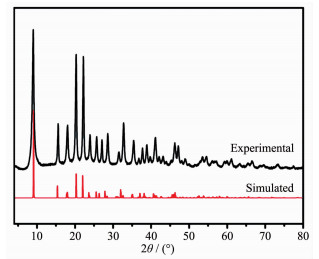
Nickel nitrate (Ni(NO3)2) and NTCA were self-assembled to form a Ni-MOF at a solvothermal temperature of 100 ℃. The PXRD pattern of the crystalline powder was shown in Fig. 1. The position of the diffraction peak and the relative intensity of diffraction were consistent with the Ni-MOF pattern reported in the literature[22], indicating that the Ni-MOF crystal was successfully synthesized.
Figure 1
2.2 General properties of the Ni@C
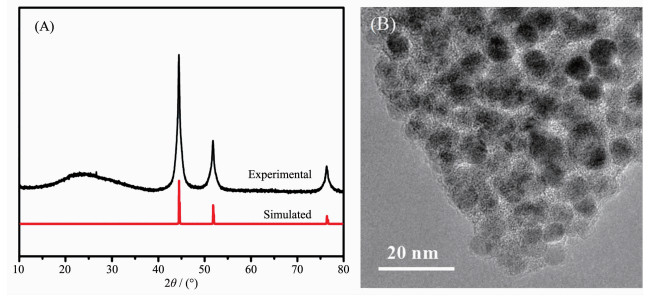
The synthesized Ni-MOF precursor underwent pyrolysis at 500 ℃ in N2 atmosphere for 3 h to afford Ni@C composites[23]. One low broad peak centered at 2θ=25° assigned to amorphous carbon[24], the other three prominent peaks near at 2θ=44.3°, 51.6° and 76.2° assigned to the (111), (200) and (220) crystalline planes of cubic-phased Ni (PDF No.04-0850), respectively (Fig. 2A). TEM showed that the Ni nanoparticles were uniformly dispersed in the carbon matrix with almost no agglomeration (Fig. 2B).
Figure 2
2.3 PXRD and TEM analysis of nickel phosphide
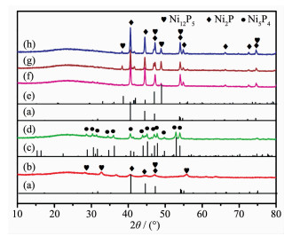
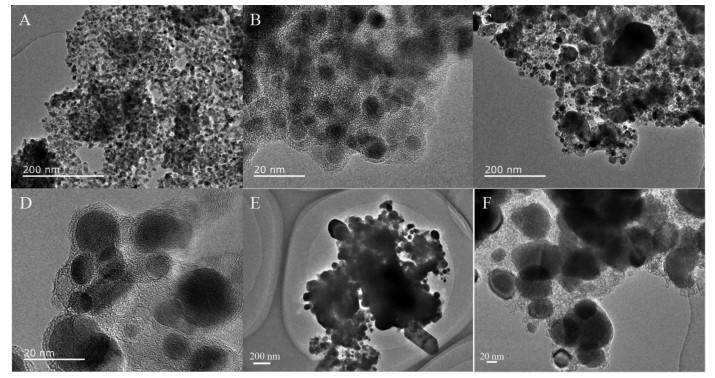
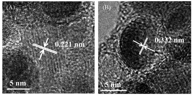
Ni@C was further phosphatized to prepare nickel phosphide nanocatalysts. Five nickel phosphide nano-catalysts were synthesized according to the different mass ratios and phosphating temperatures (Table 1). In our experiments, the phosphating temperature was found to be a key factor that affected the phase structure of the nickel phosphide nanocatalysts. The crystalline phase structure and the purity of the as-synthesized nickel phosphide materials at different phosphating temperatures were characterized by PXRD (Fig. 3). When phosphidation treatment of Ni@C was conducted at a calcination temperature of 300 ℃ for 1 h, the Ni2P (PDF No.03-065-3544) and Ni12P5 (PDF No.03-065-1623) nanoparticles could be prod-uced (Fig. 3(a, b, e)). Interestingly, the Ni5P4 nanoparti-cles could be obtained via a heat treatment at 500 ℃ for 1 h. As shown in Fig. 3(c, d), all diffraction peaks matched well with the hexagonal structure of Ni5P4 (PDF No.03-065-2075) and no extraneous peaks existed. Upon further increasing the phosphating temperature to 700 ℃, the product was a mixture of hexagonal Ni2P and hexagonal Ni12P5 phases ((Fig. 3(a, e~h)). Among five nickel phosphide materials, the crystallinity increased with the increase of tempera-ture. The morphology and structure of the nickel phosphide were further characterized by TEM (Fig. 4). The Ni2P and Ni12P5 particles in the Ni1P1-300 material were uniform in size and encapsulated in the carbon matrix (Fig. 4(A, B)). The HRTEM image (Fig. 5A) showed the lattice fringes with a distance of 0.221 nm, corresponding to the (111) lattice plane of Ni2P. As the phosphating temperature increased, the Ni5P4 particles grew to ~20 nm (Fig. 4(C, D)). The distance of the adjacent lattice fringes was calculated to be about 0.332 nm, corresponding well to the (110) lattice plane of Ni5P4 (Fig. 5B). When the temperature rises to 700 ℃, the biphasic Ni2P and Ni12P5 nanoparticles were obtained with an average particle size of 100 nm and escaped from the carbon matrix (Fig. 4(E, F)).
Figure 3
 Figure 3. PXRD patterns of Ni2P phase (PDF No.03-065- 3544) (a), Ni1P1-300 (b), Ni5P4 (PDF No.03-065-2075) (c), Ni1P1-500 (d), Ni12P5 phase (PDF No.03-065-1623) (e), Ni1P2-700 (f), Ni2P1-700 (g) and Ni1P1-700 (h)
Figure 4
Figure 5
2.4 Electrocatalytic activity
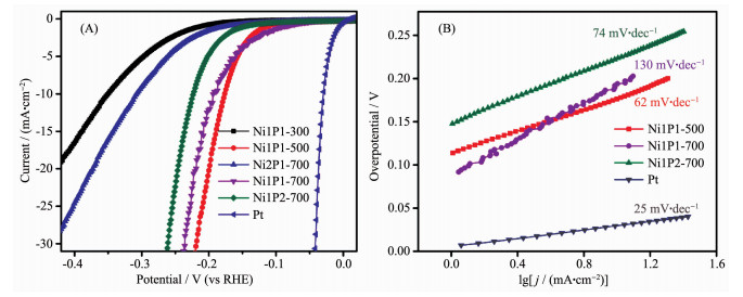
The electrocatalytic activities of nickel phosphide nanocatalysts in different phases towards HER was evaluated. The polarization curves of catalysts in 0.5 mol·L-1 H2SO4 with a slow scan rate of 2 mV·s-1 using a three electrode setup were shown in Fig. 6A. As a comparison, commercial 20%(w/w) Pt/C catalyst was also performed under the identical measurements. The glassy carbon electrode of the nickel phosphide catalysts measured under the reversible hydrogen electrode had a large current density. Generally, the overpotential (η) required for the current density of 10 mA·cm-2 (η10) was a matric relevant to solar fuel synthesis, commonly used as a standard for evaluating the HER activity of the catalyst[25]. The Ni1P1-500 required an η10 of 178 mV, while η10 of Ni1P1-700, Ni1P2-700, Ni2P1-700, and Ni1P1-300 were 193, 223, 306, and 350 mV, respectively. These datas showed that nickel phosphide with different phases had good electrocatalytic properties, and that the Ni1P1-500 catalyst consisting of Ni5P4 exhibited the highest catalytic activity. This superior HER activity can be attributed to the positive charge of Ni and the ensemble effect of P in nickel phosphide catalysts[26]. The small positive charge of Ni was beneficial to improve the catalytic activity of HER. The XPS showed that δ (Ni12P5) < δ (Ni2P) < δ (Ni5P4) (δ is the value of charges)[27], which indicated that the catalytic activity of Ni1P1-500 (Ni5P4) was better than other four catalysts. In addition, for the phosphide materials, the increase of the radio of P to Ni on the surface can also improve the catalytic activity[28]. This effect could be one explanation why a higher phosphorous content was found to be beneficial for the activity and stability of transition metal phosphides[29-30]. The molar ratios of P to Ni were 1:2.4, 1:2 and 1:1.25 in Ni12P5, Ni2P and Ni5P4, respectively, which was in accordance with our electrocatalytic results. In previous study, Ni and P sites in the nickel phosphides represented the hydride acceptor and proton acceptor center, respectively, to facilitate catalysis of the HER[13]. Moreover, the P could also facilitate the formation of Ni-hydride via electro-chemical desorption and offer more active sites[27]. Therefore, Ni1P1-500 were expected to be better HER catalysts because of more positive charge of Ni and more P-rich nature.
Figure 6
 Figure 6. Polarization data (A) and corresponding Tafel plots (B) for nickel phosphide, Pt electrodes in 0.5 mol·L-1 H2SO4
To further investigate the catalytic reaction kinetics of HER, the Tafel slope for different nickel phosphide nanocatalysts were examined by deriving from polarization curves. Under different overpotentials, the Tafel curve fitted well with the Tafel equation (η=blg|j|+a, η represents the overpotential, b represents the Tafel slope, and j represents the current density). The Tafel slope of Pt/C was 25 mV·dec-1, which was consistent with that reported in the literature[13]. In contrast, the Tafel slope of Ni1P1-500, Ni1P1-700, and Ni1P2-700 electrodes (Fig. 6B) were 62, 74, 130 mV·dec-1. The Tafel slope was a useful indicator of reaction kinetics. The smaller Tafel slope of the HER catalyst, the faster kinetics for electrochemical reactions[31]. Thus, the reaction kinetic of the HER on Ni1P1-500 was much faster than those on other samples. According to the literature reports, nickel phosphides exhibit good catalytic stability[32-33].
An overview of the hydrogen evolution reaction in acidic medium was given below with three possible rate limiting steps[34]: If Equation (1) is the rate deter-mining step, the expected slope would be 120 mV·dec-1. On the other hand, if the kinetics of the HER is limited by the Equation (2), one would expect a Tafel slope of 40 mV·dec-1. Finally, if the Equation (3) is the rate limiting step, a slope of 30 mV·dec-1 is expected[35]. In our studies, the observed Tafel slopes of Ni1P1-500 were 62 mV·dec-1, which indicated that the HER reaction was limited by Desorption-Heyrovsky reaction. Hads represents an H atom absorbed at the active site of the catalyst.
Discharge step: Volmer reaction
$ \mathrm{H}_{3} \mathrm{O}^{+}+\mathrm{e}^{-} \rightarrow \mathrm{H}_{ \mathrm{ads}}+\mathrm{H}_{2} \mathrm{O} $
(1) Desorption: Heyrovsky reaction
$ \mathrm{H}_{\mathrm{ads}}+\mathrm{H}_{3} \mathrm{O}^{+}+\mathrm{e}^{-} \rightarrow \mathrm{H}_{2}+\mathrm{H}_{2} \mathrm{O} $
(2) Recombination: Tafel reaction
$ \mathrm{H}_{ \mathrm{ads}}+\mathrm{H}_{\mathrm{ads}} \rightarrow \mathrm{H}_{2} $
(3) 2.5 XPS analysis
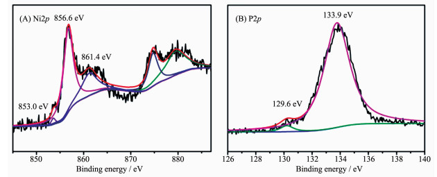
Based on previous density functional theory (DFT) calculation, the highly active HER of the Ni1P1-500 was attributed to the presence of the proton acceptor and hydride acceptor centers on the surface of Ni5P4[36]. In order to reveal the cause of HER reaction, we further analyzed the XPS spetra of Ni1P1-500. The binding energy of 853.0, 856.6 and 861.4 eV for the Ni2p3/2 energy level were observed (Fig. 7A), corres-ponding to Niδ+, oxidized Ni species and the satellite of Ni2p3/2 peak, respectively[37]. It is noteworthy that the Ni2p3/2 binding energy (853.0 eV) in this work was slightly higher than that in nickel metal (852.5~852.9 eV)[38], which suggested that the Ni in Ni1P1-500 had a very small positive charge. For the P2p region, one peaks at 133.9 eV was attributed to oxidized P species originated from the superficial oxidation of phosphide (Fig. 7B)[39], and the other peaks at 129.6 eV was attributed to P in Ni1P1-500, which suggested that the related P species had a very small negative charge because this binding energy was less than that of elemental P (130.0 eV)[40]. The results clarified that the HER catalytic activity of Ni1P1-500 may be related to the intrinsic charge properties of Ni and P[41]. Moreover, the higher δ+ value of phosphate and higher levels of phosphorus may be utilised for the HER in acidic medium[28].
Figure 7
3. Conclusions
In conclusion, we have developed nickel phosphide nanocatalysts for HER, via a MOF pyrolysis and subsequent phosphating process. The resultant nickel phosphide catalysts exhibited superior HER catalytic performance in acid solution. The sample obtained by phosphating at 500 ℃ (Ni1P1-500) was composed of Ni5P4, which exhibited excellent electro-catalytic performance in HER. The Tafel slope was 62 mV·dec-1 and the overpotential was 178 mV at a current density of 10 mA·cm-2. The excellent electro-catalytic performance might be ascribed to the presence of the proton acceptor (P site) and hydride-acceptor (Ni site) centers on the surface of nickel phosphide. More importantly, this strategy has the characteristics of simple synthesis, large-scale production and practical application, and it can also be extended to synthesize metal phosphides from other MOFs.
-
-
[1]
Walter M G, Warren E L, McKone J R, et al. Chem. Rev., 2010, 110:6446-6473 doi: 10.1021/cr1002326
-
[2]
Subbaraman R, Tripkovic D, Chang K C, et al. Nat. Mater., 2012, 11:550-557 doi: 10.1038/nmat3313
-
[3]
Jeon K J, Moon H R, Ruminski A M, et al. Nat. Mater., 2011, 10:286-290 doi: 10.1038/nmat2978
-
[4]
Turner J A. Science, 2004, 305:972-974 doi: 10.1126/science.1103197
-
[5]
Farid S, Ren S Z, Hao C. Inorg. Chem. Commun., 2018, 94:57-74 doi: 10.1016/j.inoche.2018.06.008
-
[6]
Arenz M, Stamenkovic V, Schmidt T J, et al. Surf. Sci., 2002, 506:287-296 doi: 10.1016/S0039-6028(02)01423-1
-
[7]
Fang B, Kim J H, Yu J S. Electrochem. Commun., 2008, 10:659-662 doi: 10.1016/j.elecom.2008.01.022
-
[8]
Anantharaj S, Ede S R, Sakthikumar K, et al. ACS Catal., 2016, 6:8069-8097 doi: 10.1021/acscatal.6b02479
-
[9]
Yan L T, Jiang H M, Xing Y L, et al. J. Mater. Chem. A, 2018, 6:1682-1691 doi: 10.1039/C7TA10218F
-
[10]
Lin C, Gao Z F, Yang J H, et al. J. Mater. Chem. A, 2018, 6:6387-6392 doi: 10.1039/C8TA00260F
-
[11]
Laursen A B, Patraju K R, Whitaker M J, et al. Energy Environ. Sci., 2015, 8:1027-1034 doi: 10.1039/C4EE02940B
-
[12]
Lai C G, Liu X B, Deng Y Q, et al. Inorg. Chem. Commun., 2018, 97:98-102 doi: 10.1016/j.inoche.2018.09.024
-
[13]
Popczun E J, McKone J R, Read C G, et al. J. Am. Chem. Soc., 2013, 135:9267-9270 doi: 10.1021/ja403440e
-
[14]
Laursen A B, Wexler R B, Whitaker M J, et al. ACS Catal., 2018, 8:4408-4419 doi: 10.1021/acscatal.7b04466
-
[15]
Pan Y, Sun K A, Liu S J, et al. J. Am. Chem. Soc., 2018, 140:2610-2618 doi: 10.1021/jacs.7b12420
-
[16]
Yang Y, Lun Z Y, Xia G L, et al. Energy Environ. Sci., 2015, 8:3563-3571 doi: 10.1039/C5EE02460A
-
[17]
Wang R, Dong X Y, Du J, et al. Adv. Mater., 2018, 30:1703711-1703720 doi: 10.1002/adma.201703711
-
[18]
Ma S Q, Goenaga G A, Call A V, et al. Chem. Eur. J., 2011, 17:2063-2067 doi: 10.1002/chem.201003080
-
[19]
Xu M, Han L, Han Y J, et al. J. Mater. Chem. A, 2015, 3:21471-21477 doi: 10.1039/C5TA05018A
-
[20]
Rana U, Chakrabart K, Malik S. J. Mater. Chem., 2011, 21:11098-11100 doi: 10.1039/c1jm12051d
-
[21]
Wang X G, Kolen'ko Y V, Bao X Q, et al. Angew. Chem. Int. Ed., 2015, 127:8306-8310 doi: 10.1002/ange.201502577
-
[22]
Chen L F, Zhang J, Song L J, et al. Inorg. Chem. Commun., 2005, 8:555-558 doi: 10.1016/j.inoche.2005.03.019
-
[23]
Xu D, Pan Y, Chen M Y, et al. RSC Adv., 2017, 7:26377-26383 doi: 10.1039/C7RA03162A
-
[24]
王海文, 王一丹, 殷馨, 等.无机化学学报, 2018, 35(3):369-375 http://www.wjhxxb.cn/wjhxxbcn/ch/reader/view_abstract.aspx?file_no=20190301&flag=1WANG Hai-Wen, WANG Yi-Dan, YIN Xin, et al. Chinese J. Inorg. Chem., 2018, 35(3):369-375 http://www.wjhxxb.cn/wjhxxbcn/ch/reader/view_abstract.aspx?file_no=20190301&flag=1
-
[25]
McCrory C C L, Jung S H, Peters J C, et al. J. Am. Chem. Soc., 2013, 135:16977-16987 doi: 10.1021/ja407115p
-
[26]
Huang Z P, Chen Z B, Chen Z Z, et al. ACS Nano, 2014, 8:8121-8129 doi: 10.1021/nn5022204
-
[27]
Pan Y, Liu Y R, Zhao J C, et al. J. Mater. Chem. A, 2015, 3:1656-1665 doi: 10.1039/C4TA04867A
-
[28]
Kucernak A R J, Sundaram V N N. J. Mater. Chem. A, 2014, 2:17435-17445 doi: 10.1039/C4TA03468F
-
[29]
Callejas J F, Read C G, Popczun E J, et al. Chem. Mater., 2015, 27:3769-3774 doi: 10.1021/acs.chemmater.5b01284
-
[30]
Saadi F H, Carim A I, Verlage E, et al. J. Phys. Chem. C, 2014, 118:29294-29300 doi: 10.1021/jp5054452
-
[31]
Xie J F, Li S, Zhang X D, et al. Chem. Sci., 2014, 5:4615-4620 doi: 10.1039/C4SC02019G
-
[32]
Han A L, Jin S, Chen H L, et al. J. Mater. Chem. A, 2015, 3:1941-1946 doi: 10.1039/C4TA06071G
-
[33]
He S Q, He S Y, Bo X, et al. Mater. Lett., 2018, 231:94-97 doi: 10.1016/j.matlet.2018.08.033
-
[34]
Thomas J G N. Trans. Faraday Soc., 1961, 57:1603-1611 doi: 10.1039/tf9615701603
-
[35]
Conway B E, Tilak B V. Electrochim. Acta, 2002, 47:3571-3594 doi: 10.1016/S0013-4686(02)00329-8
-
[36]
Mo Q J, Zhang W B, He L Q, et al. Appl. Catal. B, 2019, 244:620-627 doi: 10.1016/j.apcatb.2018.11.083
-
[37]
Nesbitt H W, Legrand D, Bancroft G M. Phys. Chem. Miner., 2000, 27:357-366 doi: 10.1007/s002690050265
-
[38]
Sawhill S J, Layman K A, Wyk D R V, et al. J. Catal., 2005, 231:300-313 doi: 10.1016/j.jcat.2005.01.020
-
[39]
Grosvenor A P, Wik S D, Cavell R G, et al. Inorg. Chem., 2005, 44:8988-8998 doi: 10.1021/ic051004d
-
[40]
Nefedov V I, Salyn Y V, Domashevskay E P, et al. J. Electron. Spectrosc. Relat. Phenom., 1975, 6:231-238 doi: 10.1016/0368-2048(75)80018-1
-
[41]
Li J F, Chai Y M, Liu B, et al. Appl. Catal. A, 2014, 469:434-441 doi: 10.1016/j.apcata.2013.09.047
-
[1]
-
Figure 3 PXRD patterns of Ni2P phase (PDF No.03-065- 3544) (a), Ni1P1-300 (b), Ni5P4 (PDF No.03-065-2075) (c), Ni1P1-500 (d), Ni12P5 phase (PDF No.03-065-1623) (e), Ni1P2-700 (f), Ni2P1-700 (g) and Ni1P1-700 (h)
Figure 6 Polarization data (A) and corresponding Tafel plots (B) for nickel phosphide, Pt electrodes in 0.5 mol·L-1 H2SO4
Table 1. Experimental conditions and electrocatalytic performance of nickel phosphide samples
Sample T/℃ Composition η10a / mV (vs RHE) Tafel slope / (mV·dec-1) Ni1P1-300 300 Ni2P and Ni12P5 350 — Ni1P1-500 500 Ni5P4 178 62 Ni2P1-700 306 — Ni1P1-700 700 Ni2P and Ni12P5 183 74 Ni1P2-700 223 130 aη10: Potential required for 10 mA·cm-2.  下载: 导出CSV
-


 扫一扫看文章
计量
- PDF下载量: 3
- 文章访问数: 853
- HTML全文浏览量: 51
