Table 1.
Catalytic performances of reported indium-based catalysts for CO2RR.
Citation:
Qin Cheng, Ming Huang, Qingqing Ye, Bangwei Deng, Fan Dong. Indium-based electrocatalysts for CO2 reduction to C1 products[J]. Chinese Chemical Letters,
2024, 35(6): 109112.
doi:
10.1016/j.cclet.2023.109112

Indium-based electrocatalysts for CO2 reduction to C1 products
English
Indium-based electrocatalysts for CO2 reduction to C1 products
Abstract:
Electrocatalytic CO2 reduction at mild conditions is a promising strategy to transform greenhouse gases into fuels or value-added chemicals to solve the increasingly serious environmental and energy problems. The most crucial factor in determining the CO2 reduction performance is to develop efficient electrocatalysts with high selectivity and stability. Among the various electrocatalysts, indium-based catalysts have attracted extensive attention due to their non-toxicity, low cost, and high formic acid/formate selectivity. In this work, we comprehensively review the recent development and research progress of indium-based electrocatalysts for CO2RR. The reaction mechanism, reaction pathways, structure–activity relationship, and strategies to enhance the activity of CO2RR on indium-based catalysts have also been briefly presented and discussed. Finally, the existing challenges and future developments for indium-based high-performance catalysts for CO2RR are proposed.
-
1. Introduction
The significant growing demand for fossil fuel energy resources exacerbates the energy crisis and environmental problems [1-3]. In particular, the global warming and seawater acidification due to the indiscriminate CO2 emissions are becoming more and more serious [4]. To address these energy and environmental problems, use of clean fossil energy with low carbon content, and development of non-fossil energy, such as nuclear energy, hydropower, wind energy, and solar energy would be an alternative route. In addition, converting CO2 gas to high value-added chemicals and/or fuels through development of carbon capture, utilization, and storage (CCUS) techniques has been proposed as one of the most promising strategies to deal with the energy crisis and further achieve carbon neutrality [5].
At present, various techniques have been studied for CO2 conversion, such as photochemistry [6-8], electrochemistry [9-11], thermochemistry [12,13], and biological reduction methods [14]. Among these techniques, electrocatalytic CO2 reduction reaction (CO2RR) has the following advantages: (ⅰ) Wide range of renewable electric energy sources, mainly include solar energy, wind energy, tidal energy, and biomass energy [15]; (ⅱ) Mild and controllable reaction conditions; (ⅲ) Compact and modular electrolyzers could be designed for mass production [16]. Using CO2 as a raw material and converting it into value-added fuels or valuable chemicals (CO, HCOOH, CH4, C2H4, CH3CH2OH, etc.), driven by renewable electricity, is a promising approach to reduce CO2 emission [17-20]. In addition, electrocatalytic CO2RR is gradually becoming mature in terms of fundamental research, theoretical predictions, in-situ characterization, and electrolyzer design [21]. In addition, it is in line with the goals of green economy and sustainable development.
However, electrolytic CO2RR on most catalysts usually suffers from unsatisfactory catalytic activity due to the sluggish kinetics of the CO2 activation. In addition, the accompanying hydrogen evolution reaction (HER) is a competing reaction and will decrease the target product selectivity and energy efficiency of CO2RR. Up to now, the low activity, poor product selectivity, undesirable product conversion rate, and catalyst degradation after long-term electrolysis are still the major challenges for the commercialization of electrocatalytic CO2RR [22]. Designing highly efficient and stable electrocatalysts for CO2RR could be a promising route to address these problems. Recently, p-block metal catalysts, including Bi [23-25], Sn [26-28], In [29-35], and Pb [36,37], have been widely studied for electrocatalytic CO2RR, especially for the production of formic acid/formate. Among these p-block metal-based catalysts, indium-based catalyst has attracted great attention due to the following advantages: (ⅰ) Indium has abundant resources with relatively low cost; (ⅱ) Indium is a non-toxic element with easy processing feature; (ⅲ) Excellent physical and chemical properties, such as good electrical conductivity and the property of easily forming alloys with other metals [38]; (ⅳ) High selectivity to the production of formic acid: In has a high binding energy to *HCOO, which favors the conversion of CO2 to HCOOH [39]. Up to now, various indium–based catalysts including metal structures, alloys, oxides/hydroxides, nitrides, sulfides, clusters, single-atoms, and their composites with carbon materials have been intensively synthesized and used for electrolytic CO2RR (Table 1). The catalyst types, dimensions, morphologies, defects, surface properties, and electrochemical cells all show significant influences on the final performance of CO2RR. To date, a few review articles have been focused on the development of metal–based CO2RR electrocatalysts [40-43]. However, a timely and comprehensive review on the design and development of indium-based electrocatalysts for electrolytic CO2RR is still lacking.
Table 1
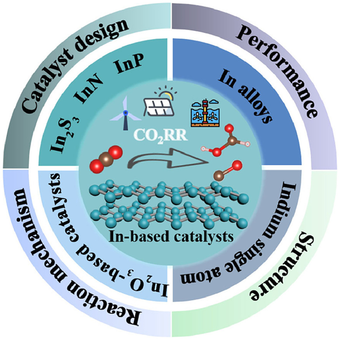
Herein, the recent development of indium-based electrocatalysts in electrolytic CO2RR to C1 products is systematically summarized and discussed. The rational design of indium-based catalysts, including structure, composition, morphology, and single-atom structure, has been proven to be effective in promoting the electrolytic CO2RR performance (Fig. 1). We first briefly introduce the possible reaction pathways for the CO2RR on indium-based electrocatalysts surface. Then we present the design strategies of various types of indium-based electrocatalysts with high performance, including the modulation of dimension, size, morphology, composition, single-atom structure, defect, heterostructure, and some other catalysts. Finally, the remaining challenges and future development in this field are envisioned.
Figure 1
 Figure 1. Summary of In-based catalyst design strategies for highly efficient electrolytic CO2RR.
2. Reaction pathways of CO2RR on indium-based electrocatalysts
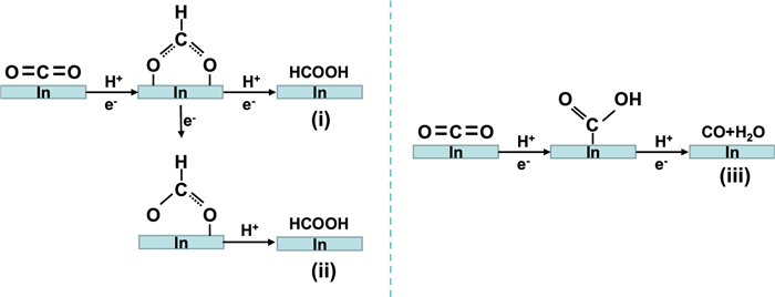
It is generally known that the formation of products in electrolytic CO2RR mainly includes three steps: CO2 adsorption on catalysts surface, the transfer of electrons/protons to the absorbed CO2 molecules, and desorption of product molecules from catalyst surface. The reaction products of CO2 on indium-based catalysts are mainly formate or CO, which is a typical two electrons/protons transfer process. The product selectivity largely depends on the first proton coupling process on the catalyst surface. In other words, whether the first proton is added to the C atom or the O atom in the activated CO2−, determining the formation of different products. At present, a large number of studies suggest that the CO2RR on indium-based catalysts surface usually has three pathways (Fig. 2) [44-47], which including (ⅰ) the two oxygen atoms in CO2− are bound to the catalyst surface, and the carbon atom is protonated to generate the HCOO* intermediate, which follows by a second electron transfer and protonation process to form HCOOH [4]; (ⅱ) unlike the former, *OCHO intermediate should be formed through an electron transfer process of the as-formed HCOO* intermediate, which will be further protonated to form HCOOH [47]; (ⅲ) different from the previous two pathways, the C atom in CO2− may also be bonded to the catalyst surface. In this case, one of the oxygen atoms will be protonated to form a COOH* intermediate, following by an electron transfer and protonation process and a further dehydration to form CO [11].
Figure 2
 Figure 2. Possible reaction pathways of electrolytic CO2RR on the surface of indium-based electrocatalyst.
3. Advanced indium-based catalysts for high-performance electrolytic CO2RR
3.1 In-based alloys
Alloying is a common and efficient approach to improve the activity and selectivity for electrolytic CO2RR. Attributing to the altered composition, electronic structure, and surface properties (such as varied electronegativity, undercoordinated active sites, surface atom distribution, and lattice mismatch), alloys show tunable catalytic activity compared to pure metals [48-50]. Until now, numerous studies have shown that the combination of binary metal elements with different electronic properties can significantly adjust the surface chemical environment and the adsorption energy of reaction intermediates during CO2RR. Many indium-based alloys have been reported for electrolytic CO2RR, however, unlike Sn and Bi, indium-based alloys are more likely to enhance the selectivity of CO [51-54].
3.1.1 Cu-In alloy
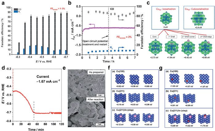
Among the numerous bimetallic catalysts, Cu-In alloys have attracted great attention due to the unique electronic structure of Cu. Rasul et al. electrodeposited In on rough Cu surface to a Cu-In alloy catalyst, exhibiting a Faraday efficiency of 95% for CO2-to-CO conversion at a potential of ‒0.7 V vs. RHE. The Faraday efficiency of CO can be maintained at 85% after electrolysis for 7 h (Figs. 3a and b) [55]. The theoretical calculations show that the introduction of In does not change the electronic properties of Cu, but In preferentially locates at the edge of Cu, which can stabilize the reaction intermediate (COOH*) and further promote the reduction of CO2 to CO (Fig. 3c). Moreover, Rasul and his group members reported the construction of Cu-In alloy interface during electrolysis process of CO2RR when using CuInO2 as the starting catalyst (Figs. 3d and e) [56]. The as-formed Cu-In catalyst shows a formate selectivity of 31% selectivity and a CO selectivity of 63% selectivity with suppressed HER. Theoretical calculations reveal that In occupies the stepped sites of Cu, and does not show a preferential adsorption of H* or CO* intermediates. While the vicinal Cu affects the adsorption of H* or CO* intermediates, and the synergistic effect of In and Cu finally attributes to the selectivity of electrolytic CO2RR (Figs. 3f and g). These studies indicate that the introduction of two metals with different properties at the two-phase interface can change the adsorption strengths of reaction intermediates, thereby changing/enhancing the selectivity of target products.
Figure 3
 Figure 3. (a) Faradaic efficiencies for CO and H2 on Cu-In alloys at different potentials. (b) Long-term stability test for Cu-In alloy at a potential 0.6 V vs. RHE. (c) Site preference of In in Cu55-Icosahedron cluster and Cu55-Cubooctahedron cluster. The energies relative to Cu55-Icosahedron are shown. Reproduced with permission [55]. Copyright 2015, Wiley-VCH Verlag GmbH & Co. KGaA. (d) Chronopotentiometric test of CuInO2 catalyst at a current density of ‒1.67 mA/cm2. (e) SEM images of Cu-In electrodes before and after electrolysis. Optimized geometries and relative adsorption energies of H (f) and CO (g) on Cu (100), Cu (211), and In-modified (211) Cu facet. Reproduced with permission [56]. Copyright 2015, The Royal Society of Chemistry.
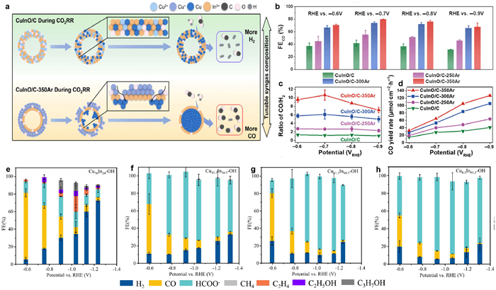
Apart from the formation of alloy interface, recent studies revealed the promotion of electrolytic CO2RR by tuning the structure and composition of Cu-In alloy. For example, by controlling the annealing temperature, Shen et al. prepared various Cu-In bimetallic catalysts with different structures (hollow spheres and double-layer hollow spheres) and different phases (CuO and Cu2O) for CO2 reduction to syngas (CO and H2) [57]. The authors found that the structure and phase of catalysts during the CO2RR process determines the formation of syngas with different compositions (Fig. 4a). After the introduction of In into Cu, the Faradaic efficiency of CO and the syngas yield increase at all potentials with increasing annealing temperature in Ar (Figs. 4b–d). In addition, the atomic composition of Cu-In alloy directly affects product selectivity during CO2RR. Xie and colleagues synthesized Cu-In hydroxides (CuxIny-OH) with tunable compositions by a simple hydrothermal method, and they found that the selectivity of products shifted from CO to formic acid when the In content was increased (Figs. 4e–h) [58]. Similarly, Hoffman's group also demonstrated that the selectivity of target product could be controlled by altering the alloy composition [59]. Therefore, by controlling the structure and composition of the catalyst for CO2RR, the selectivity of the product can be directionally improved or regulated [60,61].
Figure 4
 Figure 4. (a) Illustration shows the surface evolution of Cu-In based catalysts during CO2RR and the varying product selectivity. (b-d) Evaluation of CO2RR performance on various catalysts. Reproduced with permission [57]. Copyright 2021, Springer. Faradaic efficiencies for various products on CuxIny hydroxide catalysts: (e) Cu76In24-OH, (f) Cu43.5In56.5-OH, (g) Cu11.5In88.5-OH, (h) Cu8.5In91.5-OH. Reproduced with permission [58]. Copyright 2021, Elsevier.
3.1.2 Sn-In alloy
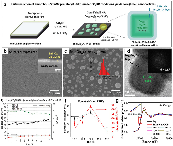
Sn and In exhibit similar features in electrocatalytic CO2RR with high selectivity for formate, and the Sn-In alloy is expected to enhance this selectivity to some extent. Pardo Pérez and his co-workers reported the formation of metal/metal oxide core-shell nanoparticles via an in situ reduction of the amorphous SnInOx film during electrocatalytic process [62]. Their results show that the in situ reduced Sn1–XInX@In1–Y was composed of Sn-rich SnIn alloy nanocore and InOx-rich SnInOx shell (Figs. 5a–d). Consequently, the in-situ formed catalyst had a Faradaic efficiency of 80% for formate without significant degradation under electrolysis for up to 10 h (Fig. 5e). Wang group prepared Sn-In core-shell nanoparticles with an InSn4 core and an amorphous In-doped tin oxide shell via a one-step method [63]. They found that the content of indium in the Sn-In alloy plays an important role in determining the activity and Faradaic efficiency of CO2 reduction to formate. The best CO2 reduction performance was achieved when the content of In was 30% (Fig. 5f). Theoretical calculations and X-ray absorption near edge structure (XANES) spectra show that In doping in SnO2 shell results in the generation of oxygen vacancies, promoting the production of formic acid while suppressing hydrogen evolution (Fig. 5g). This core@shell structure can tune CO2RR selectivity through synergistic effect between core-shell components, which offers potential advantages for electrocatalysis [26,64].
Figure 5
 Figure 5. (a) Schematic illusation of the in situ conversion of SnInOx film to Sn1-XInX@In1-YSnYOZ core@shell nanoparticles. (b) SEM image of synthesized SnInOx planar film (inset is a cross-sectional SEM image). (c) SEM image of the SnInOx film after CO2RR for 10 min. (d) TEM image of SnInOx_CAT@-1V_10 min (inset shows the corresponding FFT image). (e) Long-term stability of untreated SnInOx after electrolysis at −1.0 V for 10 h. Reproduced with permission [62]. Copyright 2021, Wiley-VCH GmbH. (f) The dependence of FEformate and jformate on the indium content in Sn-In alloy nanoparticles at −1.0 V vs. RHE. (g) Sn K-edge XANES spectrum of SnIn alloy nanoparticles at different potentials. Reproduced with permission [63]. Copyright 2021, Elsevier.
3.1.3 Bi-In alloy
Bi-In alloy has also been recognized efficient catalyst for the electroreduction of CO2 to formic acid with high selectivity. For instance, Yao et al. reported the synthesis of BiIn alloy nanoparticles using bimetallic metal-organic frameworks as precursors, which exhibited a HCOOH Faradaic efficiency of 92.5% at the current density of 300 mA/cm2. Remarkably, long-term stability for HCOOH production was achieved with the FE > 80% at the current density of 120 mA/cm2 in the MEA system for 25 h [39]. Tan et al. prepared the indium−bismuth nanosphere (In16Bi84 NS) via a facile liquid-polyol technique. The as-synthesized In16Bi84 NS exhibited ~100% formic acid faradaic efficiency at ‒1.4 V vs. RHE, and the FE could be maintained > 90% in a wide potential window (−0.84 to −1.54 V vs. RHE) [65]. The excellent catalytic performance was ascribed to the modulated electronic properties from the synergistic effect of In and Bi, enhancing the adsorption of the intermediate (HCOO*) on the catalyst surface to favor the formation of formic acid. Xiong et al. presented the controlled synthesis of bimetallic BixIny nanofiber catalysts with 3D network structure via an electrospinning process followed by electrochemical reduction. The obtained Bi5In5 nanofiber catalyst achieved a maximum FEformate of 96.8% with a production rate of ~4.55 mmol h−1 cm−2. The enhanced CO2RR performance was attributed to the large specific surface area and exposure of the InBi (200) plane, which has high reactivity and selectivity for formate [38].
3.1.4 Other In-based alloys
Apart from the In-based alloy with p-block metals and transition metals, some noble metals can also form alloys with In for electrocatalytic CO2RR. It is known that Ag-based catalysts show good selectivity to CO in CO2RR, and combining Ag with In to form a bimetallic alloy can further improve the CO2RR performance. Larrazábal et al. deposited Ag nanoparticles on In2O3 and In(OH)3 which was further transformed into Ag-In alloy during the electrolysis process [66]. Their experiments show that the Ag contents and the support catalysts both could affect the selectivity of CO, depending on the exposure of real active sites during electrolysis. It's also noting that the introduction of In into Pd catalyst to form an In-Pd alloy can suppress the CO poisoning problem in the pure Pd catalyst to a certain extent and further improve the CO selectivity [67].
Compared with monometallic catalysts, bimetallic alloy catalysts are composed of two different elements, which, to a certain extent, could change or modulate the electronic structure and geometry of active sites on catalyst surface. The catalyst electronic structure directly affects the binding with reaction intermediates and the reaction pathways. Changes in the geometry affects the local atomic arrangement of the active site, which could favor the formation of certain intermediates and effectively alter the reaction pathway. Thus, the alloying process could enhance the adsorption and activation capabilities of the catalyst, further improving the overall performance of the catalyst [50,68]. On the other hand, the introduction of another element into the indium-based catalyst to form an In-based alloy could realize the regulation of product selectivity. Although alloying can increase product diversity, the Faradaic efficiency for individual product may decrease compared to bare indium catalysts. Thus, the future research in this field needs rational design of the structure, components, and composition of the In-based alloy to exert the role of the two components to maximize the synergistic effect to produce the target product.
3.2 Atomically dispersed catalysts
3.2.1 In single atomic catalysts
Single-atom catalysts (SACs) have attracted extensive attention due to their full atom utilization efficiency and excellent catalytic performance. P-block metals (Bi [69], In [70], Sn [71]), transition metals (Fe [72], Ni [73], Zn [74]), and noble metals (Ag [75], Pd [76]) all have been used to construct single-atom catalysts. Ni SACs were the most widely used catalyst in CO2RR research. Recently, In SACs have also been reported for electrocatalytic CO2RR due to their excellent CO2 catalytic activity.
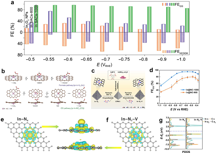
Zhang et al. prepared a series of In-NxC4−x (1 ≤ x ≤ 4) single-atom catalysts via a pyrolysis process for CO2 reduction to CO [77]. It was found that the dominate product on In2O3 NPs catalyst is formate with a small amount of CO. While the reduction product on In SACs is transformed into CO, indicating the regulation of product selectivity on indium-based catalysts (Fig. 6a). Theoretical calculations simulated the adsorption configurations and evolution processes of catalysts with small molecules, and the results showed that the change of the product from formate to CO on the In SACs is due to the transfer of the real active site from pure metallic In center to the adjacent carbon atom coordinated by the In atom (Fig. 6b). Beside, In SACs can also affect the formation energies of reaction intermediates by adjusting the hybridization energy levels. Li and his collaborators proposed two types of In SACs: four nitrogen atoms-coordinated (In-N4) SAC and three nitrogen atoms-coordinated with a vacancy (In-N3-V) SAC (Fig. 6c) [78]. Notably, In-N3-V catalyst exhibits a CO Faradaic efficiency (FECO) of 95%, which is much higher than that of In-N4 catalyst with a maximum FECO of 80% (Fig. 6d). Theoretical calculations were further performed to investigate the intrinsic relationship between SAC structure and performance. Compared with In-N4, the In atoms in In-N3-V are much easier to enrich electrons, and the vacancy makes the s and pz orbital energies of In atoms closer to the Fermi level, thereby reducing the formation energy of COOH* and improving catalytic performance (Figs. 6e–g). The selectivity of CO2RR products can be effectively tuned by regulation of the catalytic active sites and atomic structure of In SACs. In this regard, revealing the intrinsic relationship between the structure and catalytic property of SACs provides guidance for rational design of electrocatalysts.
Figure 6
 Figure 6. (a) Product selectivity of In2O3 and InSA catalysts at different potentials. (b) Proposed reaction pathways of CO2RR on pr-In-N4-(In) and pr-In-NC3-(C2). Reproduced with permission [77]. Copyright 2022, Springer Nature. (c) Schematic illustration showing the prepration of In-N3-V SACs. (d) FECO at various potentials for In@NC-900 and In@NC-1000. (e, f) Calculated charge density for In−N4 and In−N3−V catalytic centers (yellow iso-surfaces represent depletion and blue iso-surfaces represent gain of electron density. An iso-surface value was set at 0.001 e/Å3). (g) PDOS of In (s and pz orbitals In−N4 and In−N3−V) with C (s and pz orbitals in COOH*). Reproduced with permission [78]. Copyright 2022, American Chemical Society.
Even CO was the mostly reported reduction product on In SACs, formic acid/formate has also been achieved on the In-based SACs. For example, Shang et al. synthesized Inδ+-N4 SACs through wet-impregnation and pyrolysis, exhibiting a FEformate of 96% at the potential of ‒0.65 V vs. RHE and a turnover frequency (TOF) of 12500 h−1 at ‒0.95 V vs. RHE [79]. In addition, Liu and his collaborators demonstrated that In single atoms supported on carbon substrates (In-N-C) can effectively improve the electrocatalytic performance of CO2 reduction reaction, and the *OCHO intermediate formed at atomically dispersed In sites directly determine the formation of formate [80]. Due to the relatively simple coordination environment and well-defined active sites of In single atoms, the adsorption strength of intermediates can be effectively modulated by adjusting the coordination environment, thereby determining the product selectivity.
3.2.2 In-based diatomic catalysts
Although single-atom catalysts have high atom utilization efficiency, they still suffer from simple structures and lack of cooperative active sites, which limits their application in some complex reactions [81]. To solve this problem, single-atom catalysts with dual metals (diatomic catalysts) have been rationally designed. Yuan et al. prepared Cu-In diatomic catalyst by the pyrolysis of CuIn metal-organic framework (MOF). The Cu-In diatomic catalyst shows high selectivity for CO2RR to methanol, which is higher than that of pure copper single-atom catalysts [82]. The Cu-In dual atomic sites were proved to effectively hinder the hydrogen evolution reaction and promote the conversion of CO2 to methanol due to the synergistic effect between Cu and In. Fan and coworkers designed a dual-site atomic In-Ni catalyst anchored on nitrogenated carbon (InNi DS/NC). The InNi DS/NC has an excellent CO selectivity > 90% over a wide potential range (−0.5 to −0.8 V vs. RHE). In situ ATR-SEIRAS and theoretical calculations reveal that the In-Ni diatomic active sites and the O atom bridge cannot only lower the reaction energy barrier of *COOH but also suppress hydrogen evolution, promoting the CO2RR performance [83]. In addition, atomically dispersed In-Ce diatomic catalysts on nitrogen-doped carbon (In-Ce/CN) have also prepared for CO2 reduction to formic acid [84]. The introduction of Ce single atomic sites cannot only significantly promote the electron transfer during the reaction process but also optimize the In-5p orbitals, favoring the formation of. It is apparent that the two adjacent separated active sites in diatomic catalysts can provide two absorption sites and act as synergistic sites to improve catalytic activity as compared to the bare single-atom catalysts [85].
3.3 Indium oxide-based catalysts
3.3.1 In2O3
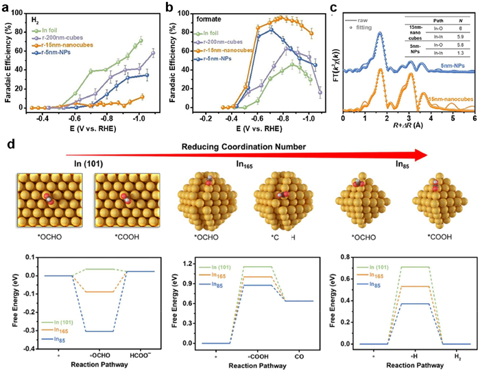
In2O3 is also a typical catalyst in CO2RR, and many studies have shown that the structure engineering of In2O3 is an effective way to enhance the CO2RR performance [86,87]. Understanding the correlation between structure and catalytic performance of catalysts is of great importance. Firstly, the size or dimension of catalyst shows a significant influence in the catalytic reaction. The size engineering of the catalyst not only can affect the specific surface area but also can tune the local electronic structure of the catalyst, showing a critical role in determining the catalytic performance. To prove this point, Huang et al. prepared 5 nm In2O3 nanoparticles (NPs) and 15 nm In2O3 nanocubes by a solvothermal reaction [88]. Compared with 200 nm In2O3 cubes and 5 nm In2O3 NPs, 15 nm In2O3 nanocubes possessed highest formate Faradaic efficiency (> 95%) and negligible side reactions with a smallest overpotential (Figs. 7a and b). Fourier-transform extended X-ray absorption fine structure (EXAFS) spectroscopy reveals that the coordination numbers of In decreases with the decrease of the size (Fig. 7c). Moreover, theoretical calculations simulated the In2O3 models with three different particle sizes. The free energy diagrams for the formation of reaction intermediates show that size reduction (coordination deficiency) is beneficial for the adsorption of all three intermediates (*OCHO, COOH*, and H*) (Fig. 7d), but the H* adsorption free energy gradually approaches the thermoneutral as the catalyst size shrinks down, indicating that HER becomes more competitive at smaller sizes. This also agrees with the experimental result that 5 nm In2O3 shows higher H2 selectivity (lower formate selectivity) than 15 nm In2O3. This study provides a new perspective on the structure-property relationship of indium-based catalysts: the size engineering of the catalyst does not necessarily mean that the smaller the better.
Figure 7
 Figure 7. Faradaic efficiencies for H2 (a) and Faradaic efficiencies for formate (b) of different catalysts at various potentials. (c) EXAFS spectra and corresponding fitting curves for 5 nm-NPs and 15 nm-nanocubes (inset is a table showng the fitting parameters). (d) Optimized configurations of *OCHO and *COOH absrobed on In (101), In165, and In85 surface, and the Gibbs free energy diagrams for the formation of HCOO–, CO and H2. Reproduced with permission [88]. Copyright 2021, Wiley-VCH GmbH.
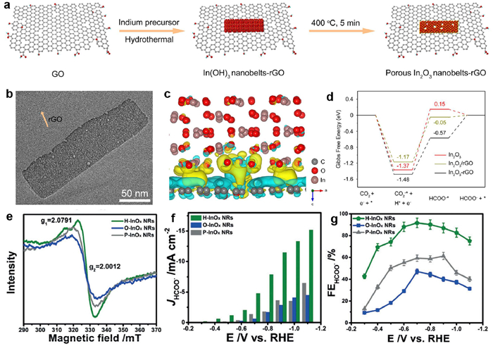
Except the size engineering, combining indium-based oxides with conductive carbon substrates to form hybrid materials (with potential chemical coupling between different components) is another effective route to modulate the CO2RR performance. For example, Zhang and coworkers revealed the role of chemical interactions between In2O3 and reduced graphene oxide (rGO) in promoting the CO2RR (Fig. 8a) [89]. In their work, porous In2O3 nanobelts were uniformly grown on reduced graphene oxide (Fig. 8b). Compared with the physically mixed In2O3-rGO catalyst, the Faradaic efficiency and partial current density of chemically bonded In2O3-rGO hybrid catalyst for formate formation were increased by 1.4 times and 3.6 times, respectively. Further, charge distribution and Gibbs free energy diagrams revealed that the strong chemical coupling between In2O3 and rGO could enhance electric conductivity and reduce the formation energy of reduction intermediates (HCOO*), thus promoting the electrolytic CO2RR activity (Figs. 8c and d). In addition, In2O3 nanoparticles dispersed on conductive carbon nanorods achieved a FEformate of 90% and the catalyst also delivered a high current density of 300 mA/cm2 when applied to a gas-diffusion electrode-based flow cell [90].
Figure 8
 Figure 8. (a) Schematic shows the preparation of porous In2O3−rGO hybrid structure. (b) TEM image of porous In2O3−rGO hybrid structure. (c) Calculated differential charge diagram for In2O3−rGO hybrid catalyst. (d) Gibbs free energy diagrams for CO2-to-formate on different catalysts. Reproduced with permission [89]. Copyright 2019, American Chemical Society. (e) Electron paramagnetic resonance (EPR) spectra of three InOx samples. Partial current density (f) and Faradaic efficiency (g) of HCOO− on three InOx samples. Reproduced with permission [91]. Copyright 2019, Wiley-VCH Verlag GmbH & Co. KGaA.
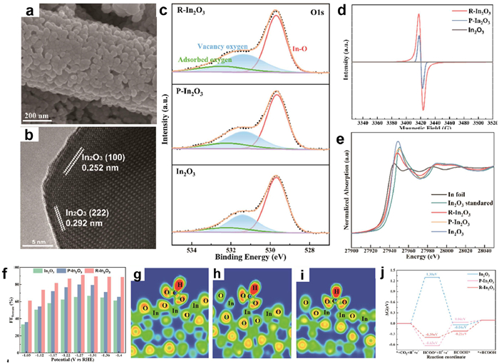
Oxygen vacancy engineering to modulate the electronic structure of In2O3 is also an effective strategy to improve the CO2RR performance. Zhang and his team synthesized InOx nanobelts with three different concentrations of oxygen vacancies, in which the highest oxygen concentration leads to the best electrolytic CO2RR performance (Figs. 8e–g) [91]. Cheng et al. synthesized In2O3 nanorods with different oxygen vacancy concentrations through an annealing atmosphere-assisted strategy for efficient electrocatalytic CO2 reduction to produce formate (Figs. 9a and b) [92]. A combination of XPS, EPR, and XAFS techniques revealed the successful tuning of oxygen vacancy concentration in In2O3 (Figs. 9c–e). Notably, the introduction of oxygen vacancies significantly enhanced the conversion activity and selectivity of CO2RR to formate (Fig. 9f). DFT calculations show that oxygen vacancies can significantly promote the interaction between HCOO* intermediates and In atoms and lower the energy barrier for the formation of HCOO*, leading to a high selectivity to CO2 conversion to formate (Figs. 9g–j). Oxygen vacancies in the electrocatalyst can promote the adsorption and activation of CO2 molecules and accelerate the electron transfer, thus improving the CO2RR performance.
Figure 9
 Figure 9. (a) A typical SEM image of oxygen vacancy-rich In2O3 catalyst (R-In2O3). (b) HRTEM image of R-In2O3. (c) O 1s XPS spectra of In2O3, P-In2O3, and R-In2O3 nanorods. (d) Corresponding EPR spectra of three In2O3 samples. (e) In K-edge XANES spectra of In2O3, P-In2O3, R-In2O3 nanorods, and reference samples. (f) Faradaic efficiencies of formate on three In2O3 catalysts. (g–i) Electronic localization function (ELF) of *HCOO on three In2O3 catalysts surfaces. (j) Gibbs free energy diagrams of CO2-to-HCOOH over three catalysts. Reproduced with permission [92]. Copyright 2023, American Chemical Society.
Various strategies have been used to enhance the CO2RR performance on In2O3 catalysts, however, the real active site under electrocatalytic conditions is not well understood. Could the active site experience reversive transformation by the reaction intermediates or the O atoms during the reaction? The catalytic mechanism is kept or changed during the dynamic evolution of the active site is still unsolved. Therefore, it is essential to monitor the evolution of the catalyst and probe reaction intermediates and/or products on the catalyst surface by combining in situ characterization techniques and theoretical calculations.
3.3.2 Doped In2O3
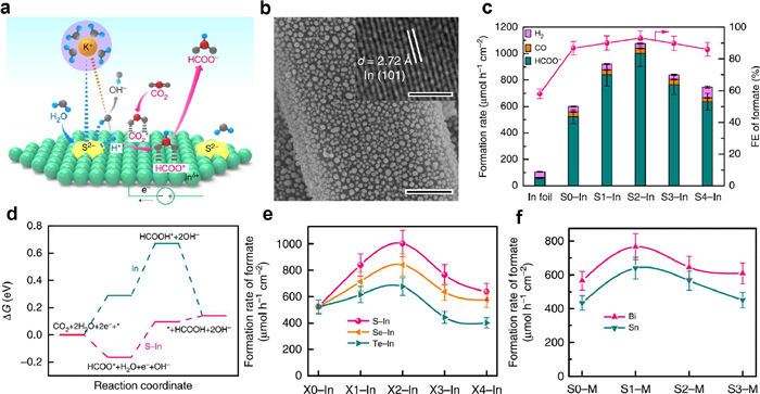
As a method to change the electronic structure of materials, element doping has been widely used in the field of semiconductors. The regulation of electronic structure can always tune the semiconductor performance by altering its band structure [93]. In the past decades, element doping has also received extensive attention in the field of electrocatalysis. It is generally believed that HER is a competing reaction of CO2RR, and the promoted activation of H2O will reduce the Faradaic efficiency of CO2RR products. However, Ma and his team broke this understanding and proposed that the activation of H2O molecules plays an important role in the reduction of CO2 on their sulfur-doped In catalyst (Figs. 10a and b) [94]. In a wide range of 25–100 mA/cm2, the FEformate on this catalyst can be maintained above 85%. The highest production rate can reach 1449 µmol h−1 cm−2 at a FEformate of 93% (Fig. 10c). DFT calculations indicated that the S doping can significantly reduce the formation energy of *HCOO on the catalyst surface (Fig. 10d). This doping effect is also effective when S was changed to other chalcogen elements such as selenium and tellurium or the metallic In was changed to other p-block metals (Bi, Sn), indicating that the doping is an effective route to promote the H2O molecules activation and further improve the electrocatalytic CO2RR performance (Figs. 10e and f). In addition to non-metal doping, metal doping of In2O3 catalyst for electrocatalytic CO2RR has also been reported. Kim et al. found that monodispersed V-doped In2O3 nanocrystals with a staged octahedral shape exhibited unusual selectivity for CO2 reduction to methanol, which was achieved by previously reported In2O3 catalysts [95]. Their results indicate that the V doping has a remarkable effect on the stabilization of intermediates, moving the reduction further and resulting in the generation of more reduced species (such as methanol).
Figure 10
 Figure 10. (a) Schematic illustration showing the role of S2− in enhanced CO2RR to formate via promoting the water dissociation and the fo rmation of H*. (b) SEM image of S−In catalyst (inset shows the HRTEM image). (c) Formation rates of different products, and FEs of formate on In foil and S−In catalysts. (d) Gibbs free energy diagrams for CO2 reduction to formate on In (101) and S−In (101) surface. (e) Formation rates of formate on S−In, Se−In and Te−In catalysts. (f) Formation rates of formate over S−Bi and S−Sn catalysts. Reproduced with permission [94]. Copyright 2019, Springer Nature.
Doping is a simple and outstanding method to modulate the electronic structure of electrocatalyst, and the CO2RR performance can be significantly enhanced by a small amount of element doping. In the enhancement of the CO2RR performance, doping works in two ways: (ⅰ) Accelerate electron transfer and improve the electric conductivity of electrocatalyst to improve catalytic activity; (ⅱ) Adjust the adsorption energies of CO2 molecules and the key reaction intermediates on the catalyst to improve the product selectivity. Therefore, the rational doping of the In2O3 catalyst could highly improve the CO2RR performance.
3.3.3 In2O3-based heterojunction
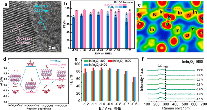
It is well known that the construction of heterojunction interface can significantly alter the electron distribution of electrocatalyst and adjust the adsorption strength of reaction intermediates to improve the CO2RR performance. Zhao et al. designed an In2O3/InN heterojunction and used it in electrolytic CO2RR for the efficient production of formate for the first time [96]. They prepared the In2O3/InN heterojunction catalyst through a hydrothermal reaction together with a further annealing in N2/NH3 atmosphere. Their high-resolution TEM images showed that the as-synthesized heterojunction interface has well-defined lattice fringes, corresponding to (101) plane of hexagonal InN and (222) plane of cubic In2O3, respectively (Fig. 11a). They applied this In2O3/InN heterojunction catalyst for CO2 reduction and found that the catalyst had a maximum FEformate of 95%. The FEformate could be maintained > 90% in a wide potential range between ‒1.37 V and ‒1.59 V (Fig. 11b). Electron localization function (ELF) analysis showed that the O atom in In2O3 and the N atom in InN could form a strong O-N coupling at the interface and offer a charge transfer channel for electron enrichment on InN surface (Fig. 11c). The Gibbs free energy change for CO2RR to formate was further calculated to explore the role of the In2O3/InN heterojunction interface in the CO2RR. The energy diagram shows that the In2O3/InN heterojunction can significantly strengthen the combination with CO2 molecules and reduce the formation energy of the *HCOO intermediate, leading to the enhancement of the formate selectivity (Fig. 11d).
Figure 11
 Figure 11. (a) High-resolution TEM image of In2O3/InN heterojunction. (b) Faradaic efficiencies for formate, CO and CH4 over In2O3 and In2O3/InN at different potentials. (c) Calculated electron localization function of In2O3/InN heterojunction. (d) Gibbs free energy diagram for CO2RR to formate on the In2O3/InN heterojunction. Reproduced with permission [96]. Copyright 2022, Elsevier. (e) Faradaic efficiencies of formate on In/In2O3-800, In/In2O3-1600, In/In2O3-2400 catalysts. (f) Operando Raman spectra of In/In2O3-1600 with diffeerent applied potentials. Reproduced with permission [97]. Copyright 2022, Wiley-VCH GmbH.
Apart from directly synthesizing electrocatalysts with heterojunction interfaces, in situ formation of heterojunction during electrolytic reactions is another effective way to enhance the catalytic activity of In-based catalysts. For example, Wulan et al. prepared the In2O3 catalyst by a fast Joule heating method and such In2O3 catalyst was in situ transformed into an In/In2O3 heterojunction catalyst during the CO2 reduction to formate [97]. The introduction of the heterojunction interface can tune the electronic structure of In and accelerate the protonation process of the adsorbed bicarbonate species, leading to a high FEformate of 94%. The in situ experimental characterizations and theoretical calculations show that the In/In2O3 heterojunction catalyst can always maintain stable In-O species as real active sites under different electrolysis conditions (Figs. 11e and f).
The rational design of heterojunction catalyst through a feasible strategy to modulate the interfacial structures and properties is promising strategy to further improve the CO2RR performance on In2O3 catalysts. However, revealing the structural evolution and real active sites of electrocatalysts during electrocatalytic reduction is challenging and of great significance to build the structure-activity relationship to further synthesize high-performance catalyst and to deeply understand the CO2RR reduction mechanism.
3.4 Other indium-based catalysts
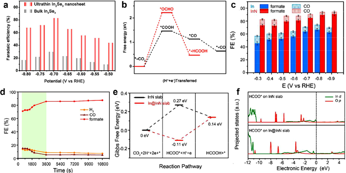
In addition to the catalysts mentioned above, indium sulfide or selenide-based composites have also been fabricated for electrocatalytic CO2RR. Ning et al. prepared a GO supported In2S3 composite (In2S3-GO), which showed a high formate selectivity due to the high specific surface area and sufficient exposure of the (440) plane of In2S3 nanosheets [98]. Similarly, Liu et al. prepared the In nanoparticles-decorated In2S3 during the electrolytic CO2RR [99]. The In–In2S3 hybrid catalyst showed a remarkable current density (for carbonaceous product) of 62.1 mA/cm2 with a maximum FEformate of 76%. The improved catalytic activity was due to the increased carrier density and the lower work function after decoration of In nanoparticles, benefiting the CO2 activation. In2Se3 catalyst has also been used for electrocatalytic CO2RR, and the Faradaic efficiency of CO reaches 89% (Fig. 12a) [100]. DFT calculations suggested that the exposed Se atoms in In2Se3 could stabilize *COOH intermediates and thus boost the electrochemical performance of the CO2-to-CO conversion (Fig. 12b). Moreover, Zhang et al. synthesized a highly efficient InN electrocatalyst which showed a FE of 95% for carbonaceous product (Figs. 12c and d) [101]. It was found that the InN was converted to an In-rich catalyst during the CO2RR process. They proposed that the surface reconstruction resulted in a surface charge redistribution, significantly facilitating the adsorption of HCOO* and thus favoring the CO2 reduction to formate (Figs. 12e and f).
Figure 12
 Figure 12. (a) Faradaic efficiencies of CO on ultrathin In2Se3 nanosheet and bulk In2Se3 at different potentials. (b) Gibbs free energy diagrams of the formation of CO and HCOOH on In2Se3 (001) surface. Reproduced with permission [100]. Copyright 2019, Elsevier. (c) Faradaic efficiencies for different products over InN and In nanosheets at different applied potentials. (d) Faradaic efficiencies for different products over InN nanosheets at −0.9 V vs. RHE for 3 h. (e) Gibbs free energy diagrams of the formation of HCOOH on InN and In@InN slabs. (f) Projected density of states (PDOS) of HCOO* intermediates adsorbed on InN and In@InN slabs. Reproduced with permission [101]. Copyright 2020, American Chemical Society.
4. Summary and outlook
In this review, we briefly reviewed the possible reaction pathways on In-based catalysts and the recently reported various In-based electrocatalysts were comprehensively and systematically summarized with a focus on their synthetic strategies, structures, catalytic performance, and reaction mechanisms. Strategies such as alloying, creating single-atom sites, element doping, heterojunction interface engineering, and defect engineering have significantly improved the catalytic performance of In-based catalysts for electrolytic CO2RR. Nevertheless, there is still plenty of room to further develop highly efficient In-based catalysts for a wide range of practical and commercial applications. In future, more research focus should be paid on the economical production of stable In-based electrocatalyst, the deep understanding of dynamic active sites, and the potential industrialization of the electrolytic CO2RR.
Firstly, most of the In-based catalysts suffered from complicated preparation processes. The development of a simple and scalable synthetic route to synthesize highly efficient In-based electrocatalysts is challenging but of significance for commercialization. The preparation strategies such as electroplating/electrodeposition, hydrothermal/solvothermal reaction, fast Joule-heating or the combination of these techniques might be helpful for large-scale production of stable In-based catalysts with low cost. Moreover, very few works have evaluated the long-term stability (> 100 h) of In-based electrocatalysts; therefore, the chemical stability of In-based catalysts also needs further exploration to meet the industrial requirement for long-term electrolysis.
Secondly, the structure and chemical states of In-based electrocatalysts always change during the CO2RR reduction process due to the applied large negative potentials and the possible transformation in the used electrolytes. To exactly identify the real active sites and correctly unveil the intrinsic reaction mechanism of electrolytic CO2RR, in situ and/or operando characterizations techniques such as X-ray diffraction (XRD), electron paramagnetic resonance (EPR), Raman spectroscopy, attenuated total reflectance-Fourier transform infrared spectroscopy (ATR-FTIR), and X-ray absorption spectroscopy (XAS) should be used to monitor the phase/chemical state changes of In-based catalysts, the absorption/desorption of reaction intermediates during the electrolytic CO2RR process. Meanwhile, the combination of theoretical calculation and in situ technique could be an effective way to deeply understand the reaction mechanism at the molecular level, and to provide a guidance for the rational design of highly-efficient electrocatalysts.
Finally, optimizing the cathode/anode reactions to improve energy utilization efficiency should also be considered. Specifically, the reactor design, the local environment, and CO2 gas source should be optimized to improve the catalytic performance and reduce the cost. The current H-type cells always show limit current densities, and thus new types of electrolyzers, such as flow cells and membrane electrode assembly (MEA) systems, are needed to be further developed for practical applications. In addition, for liquid-phase products such as formic acid, the use of solid-state electrolytes is of significance because they can directly and effectively separate the liquid products during the CO2RR process, greatly reducing the cost of product separation. Finally, the integration of CO2-based battery devices to fulfill the high efficiency CO2 utilization and conversion should also be developed.
Declaration of competing interest
The authors declare that they have no known competing financial interests or personal relationships that could have appeared to influence the work reported in this paper.
Acknowledgments
This work was supported by National Science Foundation of China (Nos. 22225606, 22261142663 and 22176029), the Excellent Youth Foundation of Sichuan Scientific Committee (No. 2021JDJQ0006).
-
-
[1]
D.Y.C. Leung, G. Caramanna, M.M. Maroto-Valer, Renew. Sustain. Energy Rev. 39 (2014) 426–443. doi: 10.1016/j.rser.2014.07.093
-
[2]
W.H. Wang, Y. Himeda, J.T. Muckerman, et al., Chem. Rev. 115 (2015) 12936–12973. doi: 10.1021/acs.chemrev.5b00197
-
[3]
B. Deng, X. Zhao, Y. Li, et al., Sci. China Chem. 66 (2022) 78–95.
-
[4]
L. Li, X. Li, Y. Sun, et al., Chem. Soc. Rev. 51 (2022) 1234–1252. doi: 10.1039/D1CS00893E
-
[5]
K. Jiang, P. Ashworth, S. Zhang, et al., Renew. Sustain. Energy Rev. 119 (2020) 109601. doi: 10.1016/j.rser.2019.109601
-
[6]
J. Yu, J. Low, W. Xiao, et al., J. Am. Chem. Soc. 136 (2014) 8839–8842. doi: 10.1021/ja5044787
-
[7]
J. Low, B. Cheng, J. Yu, Appl. Surf. Sci. 392 (2017) 658–686. doi: 10.1016/j.apsusc.2016.09.093
-
[8]
Y. Zhao, G.I.N. Waterhouse, G. Chen, et al., Chem. Soc. Rev. 48 (2019) 1972–2010. doi: 10.1039/C8CS00607E
-
[9]
A. Vasileff, Y. Zheng, S.Z. Qiao, Adv. Energy Mater. 7 (2017) 1700759. doi: 10.1002/aenm.201700759
-
[10]
L. Zhang, Z.J. Zhao, J. Gong, Angew. Chem. Int. Ed. 56 (2017) 11326–11353. doi: 10.1002/anie.201612214
-
[11]
J. Wu, Y. Huang, W. Ye, et al., Adv. Sci. 4 (2017) 1700194. doi: 10.1002/advs.201700194
-
[12]
P. Gao, S. Li, X. Bu, et al., Nat. Chem. 9 (2017) 1019–1024. doi: 10.1038/nchem.2794
-
[13]
W. Li, H. Wang, X. Jiang, et al., RSC Adv. 8 (2018) 7651–7669. doi: 10.1039/C7RA13546G
-
[14]
Y. Chen, C. Xu, S. Vaidyanathan, Appl. Energy 261 (2020) 114420. doi: 10.1016/j.apenergy.2019.114420
-
[15]
M. Bevilacqua, J. Filippi, H.A. Miller, et al., Energy Technol 3 (2015) 197–210. doi: 10.1002/ente.201402166
-
[16]
M. Jouny, W. Luc, F. Jiao, Ind. Eng. Chem. Res. 57 (2018) 2165–2177. doi: 10.1021/acs.iecr.7b03514
-
[17]
Y. Zhai, P. Han, Q. Yun, et al., eScience 2 (2022) 467–485. doi: 10.1016/j.esci.2022.09.002
-
[18]
J. Han, N. Wang, X. Li, et al., eScience 2 (2022) 623–631. doi: 10.1016/j.esci.2022.06.003
-
[19]
K. Wang, D. Liu, L. Liu, et al., eScience 2 (2022) 518–528. doi: 10.1016/j.esci.2022.08.002
-
[20]
Z. Zhu, Z. Li, J. Wang, et al., eScience 2 (2022) 445–452. doi: 10.1016/j.esci.2022.05.002
-
[21]
Z.W. Seh, J. Kibsgaard, C.F. Dickens, et al., Science 355 (2017) eaad4998. doi: 10.1126/science.aad4998
-
[22]
J. Masa, C. Andronescu, W. Schuhmann, Angew. Chem. Int. Ed. 59 (2020) 15298–15312. doi: 10.1002/anie.202007672
-
[23]
Z. Zhang, M. Chi, G.M. Veith, et al., ACS Catal. 6 (2016) 6255–6264. doi: 10.1021/acscatal.6b01297
-
[24]
G. Wen, D.U. Lee, B. Ren, et al., Adv. Energy Mater. 8 (2018) 1802427. doi: 10.1002/aenm.201802427
-
[25]
X. Zhang, T. Lei, Y. Liu, et al., Appl. Catal. B 218 (2017) 46–50. doi: 10.1016/j.apcatb.2017.06.032
-
[26]
W. Luc, C. Collins, S. Wang, et al., J. Am. Chem. Soc. 139 (2017) 1885–1893. doi: 10.1021/jacs.6b10435
-
[27]
Z. Chen, M.R. Gao, N. Duan, et al., Appl. Catal. B 277 (2020) 119252. doi: 10.1016/j.apcatb.2020.119252
-
[28]
J. Li, J. Jiao, H. Zhang, et al., ACS Sustain. Chem. Eng. 8 (2020) 4975–4982. doi: 10.1021/acssuschemeng.0c01070
-
[29]
S. Wang, B.Y. Guan, X.W.D. Lou, J. Am. Chem. Soc. 140 (2018) 5037–5040. doi: 10.1021/jacs.8b02200
-
[30]
M. Tahir, N.S. Amin, Appl. Catal. B 162 (2015) 98–109. doi: 10.1016/j.apcatb.2014.06.037
-
[31]
F. Ye, J. Gao, Y. Chen, Y. Fang, Sustain. Energy Fuels 4 (2020) 3726–3731. doi: 10.1039/D0SE00498G
-
[32]
W.J. Dong, C.J. Yoo, J.L. Lee, ACS Appl. Mater. Interfaces 9 (2017) 43575–43582. doi: 10.1021/acsami.7b10308
-
[33]
S. Wang, Z. Wu, C. Xu, et al., ACS Appl. Mater. Interfaces 14 (2022) 45423–45432. doi: 10.1021/acsami.2c13286
-
[34]
Y. Liang, W. Zhou, Y. Shi, et al., Sci. Bull. 65 (2020) 1547–1554. doi: 10.1016/j.scib.2020.04.022
-
[35]
W. Yang, Y. Zhao, S. Chen, et al., Inorg. Chem. 59 (2020) 12437–12444. doi: 10.1021/acs.inorgchem.0c01544
-
[36]
J. García, C. Jiménez, F. Martínez, et al., J. Catal. 367 (2018) 72–80. doi: 10.1016/j.jcat.2018.08.017
-
[37]
Y. Kwon, J. Lee, Electrocatalysis 1 (2010) 108–115. doi: 10.1007/s12678-010-0017-y
-
[38]
Y. Li, Y. Jin, X. Zong, et al., J. Mater. Chem. A 11 (2023) 11445–11453. doi: 10.1039/D3TA01481A
-
[39]
K. Yao, H. Wang, X. Yang, et al., Appl. Catal. B 311 (2022) 121377. doi: 10.1016/j.apcatb.2022.121377
-
[40]
T. Ren, Z. Miao, L. Ren, et al., Small 19 (2023) 2205168. doi: 10.1002/smll.202205168
-
[41]
M. Yu, P.F. Sui, X.Z. Fu, et al., Adv. Energy Mater. 13 (2023) 2203191. doi: 10.1002/aenm.202203191
-
[42]
N. Han, P. Ding, L. He, et al., Adv. Energy Mater. 10 (2020) 1902338. doi: 10.1002/aenm.201902338
-
[43]
D. Xia, H. Yu, H. Xie, et al., Nanoscale 14 (2022) 7957–7973. doi: 10.1039/D2NR01900K
-
[44]
R. Kortlever, J. Shen, K.J.P. Schouten, et al., J. Phys. Chem. Lett. 6 (2015) 4073–4082. doi: 10.1021/acs.jpclett.5b01559
-
[45]
A.A. Peterson, F. Abild-Pedersen, F. Studt, et al., Energy Environ. Sci. 3 (2010) 1311–1315. doi: 10.1039/c0ee00071j
-
[46]
H.A. Hansen, J.B. Varley, A.A. Peterson, et al., J. Phys. Chem. Lett. 4 (2013) 388–392. doi: 10.1021/jz3021155
-
[47]
J.T. Feaster, C. Shi, E.R. Cave, et al., ACS Catal. 7 (2017) 4822–4827. doi: 10.1021/acscatal.7b00687
-
[48]
S. Nitopi, E. Bertheussen, S.B. Scott, et al., Chem. Rev. 119 (2019) 7610–7672. doi: 10.1021/acs.chemrev.8b00705
-
[49]
C. Xiao, J. Zhang, ACS Nano 15 (2021) 7975–8000. doi: 10.1021/acsnano.0c10697
-
[50]
J. He, N.J.J. Johnson, A. Huang, et al., ChemSusChem 11 (2018) 48–57. doi: 10.1002/cssc.201701825
-
[51]
H. Xiang, S. Rasul, B. Hou, et al., ACS Appl. Mater. Interfaces 12 (2020) 601–608. doi: 10.1021/acsami.9b16862
-
[52]
W. Luo, W. Xie, R. Mutschler, et al., ACS Catal. 8 (2018) 6571–6581. doi: 10.1021/acscatal.7b04457
-
[53]
O. Martin, A.J. Martín, C. Mondelli, et al., Angew. Chem. Int. Ed. 55 (2016) 6261–6265. doi: 10.1002/anie.201600943
-
[54]
M. Zhu, P. Tian, J. Li, et al., ChemSusChem 12 (2019) 3955–3959. doi: 10.1002/cssc.201901884
-
[55]
S. Rasul, D.H. Anjum, A. Jedidi, et al., Angew. Chem. Int. Ed. 54 (2015) 2146–2150. doi: 10.1002/anie.201410233
-
[56]
A. Jedidi, S. Rasul, D. Masih, et al., J. Mater. Chem. A 3 (2015) 19085–19092. doi: 10.1039/C5TA05669A
-
[57]
C. Shen, P. Wang, L. Li, et al., Nano Res. 15 (2021) 528–534.
-
[58]
Q. Xie, G.O. Larrazábal, M. Ma, et al., J. Energy Chem. 63 (2021) 278–284. doi: 10.1016/j.jechem.2021.09.008
-
[59]
Z.B. Hoffman, T.S. Gray, K.B. Moraveck, et al., ACS Catal. 7 (2017) 5381–5390. doi: 10.1021/acscatal.7b01161
-
[60]
S. Ma, M. Sadakiyo, M. Heima, et al., J. Am. Chem. Soc. 139 (2017) 47–50. doi: 10.1021/jacs.6b10740
-
[61]
P. Wang, M. Qiao, Q. Shao, et al., Nat. Commun. 9 (2018) 4933. doi: 10.1038/s41467-018-07419-z
-
[62]
L.C. Pardo Pérez, D. Teschner, E. Willinger, et al., Adv. Funct. Mater. 31 (2021) 2103601. doi: 10.1002/adfm.202103601
-
[63]
J. Wang, S. Ning, M. Luo, et al., Appl. Catal. B 288 (2021) 119979. doi: 10.1016/j.apcatb.2021.119979
-
[64]
G.O. Larrazábal, A.J. Martín, S. Mitchell, et al., ACS Catal. 6 (2016) 6265–6274. doi: 10.1021/acscatal.6b02067
-
[65]
D. Tan, W. Lee, Y.E. Kim, et al., ACS Appl. Mater. Interfaces 14 (2022) 28890–28899. doi: 10.1021/acsami.2c05596
-
[66]
G.O. Larrazábal, A.J. Martín, S. Mitchell, et al., J. Catal. 343 (2016) 266–277. doi: 10.1016/j.jcat.2015.12.014
-
[67]
D. Pavesi, F. Dattila, R.C.J. Van de Poll, et al., J. Catal. 402 (2021) 229–237. doi: 10.1016/j.jcat.2021.08.021
-
[68]
L. Liu, H. Akhoundzadeh, M. Li, et al., Small Methods 31 (2023) 2300482.
-
[69]
Y. Wang, T. Liu, Y. Li, Chem. Sci. 13 (2022) 6366–6372. doi: 10.1039/D2SC01593E
-
[70]
W. Guo, X. Tan, J. Bi, et al., J. Am. Chem. Soc. 143 (2021) 6877–6885. doi: 10.1021/jacs.1c00151
-
[71]
X. Zu, X. Li, W. Liu, et al., Adv. Mater. 31 (2019) 1808135. doi: 10.1002/adma.201808135
-
[72]
H. Zhang, J. Li, S. Xi, et al., Angew. Chem. 58 (2019) 14871–14876. doi: 10.1002/anie.201906079
-
[73]
M. Huang, B. Deng, X. Zhao, et al., ACS Nano 16 (2022) 2110–2119. doi: 10.1021/acsnano.1c07746
-
[74]
S. Li, S. Zhao, X. Lu, et al., Angew. Chem. Int. Ed. 60 (2021) 22826–22832. doi: 10.1002/anie.202107550
-
[75]
N. Zhang, X. Zhang, L. Tao, et al., Angew. Chem. Int. Ed. 60 (2021) 6170–6176. doi: 10.1002/anie.202014718
-
[76]
Q. He, J.H. Lee, D. Liu, et al., Adv. Funct. Mater. 30 (2020) 2000407. doi: 10.1002/adfm.202000407
-
[77]
J. Zhang, G. Zeng, L. Chen, et al., Nano Res. 15 (2022) 4014–4022. doi: 10.1007/s12274-022-4177-x
-
[78]
S. Li, X. Lu, S. Zhao, et al., ACS Catal. 12 (2022) 7386–7395. doi: 10.1021/acscatal.2c01805
-
[79]
H. Shang, T. Wang, J. Pei, et al., Angew. Chem. Int. Ed. 59 (2020) 22465–22469. doi: 10.1002/anie.202010903
-
[80]
P. Lu, X. Tan, H. Zhao, et al., ACS Nano 15 (2021) 5671–5678. doi: 10.1021/acsnano.1c00858
-
[81]
Z. Zhang, J. Zhu, S. Chen, et al., Angew. Chem. Int. Ed. 62 (2023) e202215136. doi: 10.1002/anie.202215136
-
[82]
J. Yuan, Y. Chen, F. Liu, et al., Catal. Commun. 177 (2023) 106640. doi: 10.1016/j.catcom.2023.106640
-
[83]
Z. Fan, R. Luo, Y. Zhang, et al., Angew. Chem. Int. Ed. 62 (2023) e202216326. doi: 10.1002/anie.202216326
-
[84]
Z. Liang, L. Song, M. Sun, et al., Nano Res. 16 (2023) 8757–8764. doi: 10.1007/s12274-023-5481-9
-
[85]
Z. Liang, L. Song, M. Sun, et al., Sci. Adv. 7 (2021) eabl4915. doi: 10.1126/sciadv.abl4915
-
[86]
C.W. Li, M.W. Kanan, J. Am. Chem. Soc. 134 (2012) 7231–7234. doi: 10.1021/ja3010978
-
[87]
R. Kas, R. Kortlever, A. Milbrat, et al., Phys. Chem. Chem. Phys. 16 (2014) 12194–12201. doi: 10.1039/C4CP01520G
-
[88]
Y. Huang, X. Mao, G. Yuan, et al., Angew. Chem. Int. Ed. 60 (2021) 15844–15848. doi: 10.1002/anie.202105256
-
[89]
Z. Zhang, F. Ahmad, W. Zhao, et al., Nano Lett. 19 (2019) 4029–4034. doi: 10.1021/acs.nanolett.9b01393
-
[90]
B. Pan, G. Yuan, X. Zhao, et al., Small Sci. 1 (2021) 2100029. doi: 10.1002/smsc.202100029
-
[91]
J. Zhang, R. Yin, Q. Shao, et al., Angew. Chem. Int. Ed. 58 (2019) 5609–5613. doi: 10.1002/anie.201900167
-
[92]
Q. Cheng, M. Huang, L. Xiao, et al., ACS Catal. 13 (2023) 4021–4029. doi: 10.1021/acscatal.2c06228
-
[93]
D. Dvoranová, V. Brezová, M. Mazúr, et al., Appl. Catal. B 37 (2002) 91–105. doi: 10.1016/S0926-3373(01)00335-6
-
[94]
W. Ma, S. Xie, X.G. Zhang, et al., Nat. Commun. 10 (2019) 892. doi: 10.1038/s41467-019-08805-x
-
[95]
M.G. Kim, J. Jeong, Y. Choi, et al., ACS Appl. Mater. Interfaces 12 (2020) 11890–11897. doi: 10.1021/acsami.9b19584
-
[96]
X. Zhao, M. Huang, B. Deng, et al., Chem. Eng. J. 437 (2022) 135114. doi: 10.1016/j.cej.2022.135114
-
[97]
B. Wulan, X. Cao, D. Tan, et al., Adv. Funct. Mater. 33 (2023) 2209114. doi: 10.1002/adfm.202209114
-
[98]
H. Ning, X. Fei, Z. Tan, et al., ACS Appl. Nano Mater. 5 (2022) 2335–2342. doi: 10.1021/acsanm.1c04016
-
[99]
X. Yuan, Y. Luo, B. Zhang, et al., Chem. Commun. 56 (2020) 4212–4215. doi: 10.1039/C9CC10078D
-
[100]
F. Lü, G. Qi, X. Liu, et al., Electrochem. Commun. 103 (2019) 127–132. doi: 10.1016/j.elecom.2019.05.020
-
[101]
A. Zhang, Y. Liang, H. Li, et al., Nano Lett. 20 (2020) 8229–8235. doi: 10.1021/acs.nanolett.0c03345
-
[1]
-
Figure 1 Summary of In-based catalyst design strategies for highly efficient electrolytic CO2RR.
Figure 2 Possible reaction pathways of electrolytic CO2RR on the surface of indium-based electrocatalyst.
Figure 3 (a) Faradaic efficiencies for CO and H2 on Cu-In alloys at different potentials. (b) Long-term stability test for Cu-In alloy at a potential 0.6 V vs. RHE. (c) Site preference of In in Cu55-Icosahedron cluster and Cu55-Cubooctahedron cluster. The energies relative to Cu55-Icosahedron are shown. Reproduced with permission [55]. Copyright 2015, Wiley-VCH Verlag GmbH & Co. KGaA. (d) Chronopotentiometric test of CuInO2 catalyst at a current density of ‒1.67 mA/cm2. (e) SEM images of Cu-In electrodes before and after electrolysis. Optimized geometries and relative adsorption energies of H (f) and CO (g) on Cu (100), Cu (211), and In-modified (211) Cu facet. Reproduced with permission [56]. Copyright 2015, The Royal Society of Chemistry.
Figure 4 (a) Illustration shows the surface evolution of Cu-In based catalysts during CO2RR and the varying product selectivity. (b-d) Evaluation of CO2RR performance on various catalysts. Reproduced with permission [57]. Copyright 2021, Springer. Faradaic efficiencies for various products on CuxIny hydroxide catalysts: (e) Cu76In24-OH, (f) Cu43.5In56.5-OH, (g) Cu11.5In88.5-OH, (h) Cu8.5In91.5-OH. Reproduced with permission [58]. Copyright 2021, Elsevier.
Figure 5 (a) Schematic illusation of the in situ conversion of SnInOx film to Sn1-XInX@In1-YSnYOZ core@shell nanoparticles. (b) SEM image of synthesized SnInOx planar film (inset is a cross-sectional SEM image). (c) SEM image of the SnInOx film after CO2RR for 10 min. (d) TEM image of SnInOx_CAT@-1V_10 min (inset shows the corresponding FFT image). (e) Long-term stability of untreated SnInOx after electrolysis at −1.0 V for 10 h. Reproduced with permission [62]. Copyright 2021, Wiley-VCH GmbH. (f) The dependence of FEformate and jformate on the indium content in Sn-In alloy nanoparticles at −1.0 V vs. RHE. (g) Sn K-edge XANES spectrum of SnIn alloy nanoparticles at different potentials. Reproduced with permission [63]. Copyright 2021, Elsevier.
Figure 6 (a) Product selectivity of In2O3 and InSA catalysts at different potentials. (b) Proposed reaction pathways of CO2RR on pr-In-N4-(In) and pr-In-NC3-(C2). Reproduced with permission [77]. Copyright 2022, Springer Nature. (c) Schematic illustration showing the prepration of In-N3-V SACs. (d) FECO at various potentials for In@NC-900 and In@NC-1000. (e, f) Calculated charge density for In−N4 and In−N3−V catalytic centers (yellow iso-surfaces represent depletion and blue iso-surfaces represent gain of electron density. An iso-surface value was set at 0.001 e/Å3). (g) PDOS of In (s and pz orbitals In−N4 and In−N3−V) with C (s and pz orbitals in COOH*). Reproduced with permission [78]. Copyright 2022, American Chemical Society.
Figure 7 Faradaic efficiencies for H2 (a) and Faradaic efficiencies for formate (b) of different catalysts at various potentials. (c) EXAFS spectra and corresponding fitting curves for 5 nm-NPs and 15 nm-nanocubes (inset is a table showng the fitting parameters). (d) Optimized configurations of *OCHO and *COOH absrobed on In (101), In165, and In85 surface, and the Gibbs free energy diagrams for the formation of HCOO–, CO and H2. Reproduced with permission [88]. Copyright 2021, Wiley-VCH GmbH.
Figure 8 (a) Schematic shows the preparation of porous In2O3−rGO hybrid structure. (b) TEM image of porous In2O3−rGO hybrid structure. (c) Calculated differential charge diagram for In2O3−rGO hybrid catalyst. (d) Gibbs free energy diagrams for CO2-to-formate on different catalysts. Reproduced with permission [89]. Copyright 2019, American Chemical Society. (e) Electron paramagnetic resonance (EPR) spectra of three InOx samples. Partial current density (f) and Faradaic efficiency (g) of HCOO− on three InOx samples. Reproduced with permission [91]. Copyright 2019, Wiley-VCH Verlag GmbH & Co. KGaA.
Figure 9 (a) A typical SEM image of oxygen vacancy-rich In2O3 catalyst (R-In2O3). (b) HRTEM image of R-In2O3. (c) O 1s XPS spectra of In2O3, P-In2O3, and R-In2O3 nanorods. (d) Corresponding EPR spectra of three In2O3 samples. (e) In K-edge XANES spectra of In2O3, P-In2O3, R-In2O3 nanorods, and reference samples. (f) Faradaic efficiencies of formate on three In2O3 catalysts. (g–i) Electronic localization function (ELF) of *HCOO on three In2O3 catalysts surfaces. (j) Gibbs free energy diagrams of CO2-to-HCOOH over three catalysts. Reproduced with permission [92]. Copyright 2023, American Chemical Society.
Figure 10 (a) Schematic illustration showing the role of S2− in enhanced CO2RR to formate via promoting the water dissociation and the fo rmation of H*. (b) SEM image of S−In catalyst (inset shows the HRTEM image). (c) Formation rates of different products, and FEs of formate on In foil and S−In catalysts. (d) Gibbs free energy diagrams for CO2 reduction to formate on In (101) and S−In (101) surface. (e) Formation rates of formate on S−In, Se−In and Te−In catalysts. (f) Formation rates of formate over S−Bi and S−Sn catalysts. Reproduced with permission [94]. Copyright 2019, Springer Nature.
Figure 11 (a) High-resolution TEM image of In2O3/InN heterojunction. (b) Faradaic efficiencies for formate, CO and CH4 over In2O3 and In2O3/InN at different potentials. (c) Calculated electron localization function of In2O3/InN heterojunction. (d) Gibbs free energy diagram for CO2RR to formate on the In2O3/InN heterojunction. Reproduced with permission [96]. Copyright 2022, Elsevier. (e) Faradaic efficiencies of formate on In/In2O3-800, In/In2O3-1600, In/In2O3-2400 catalysts. (f) Operando Raman spectra of In/In2O3-1600 with diffeerent applied potentials. Reproduced with permission [97]. Copyright 2022, Wiley-VCH GmbH.
Figure 12 (a) Faradaic efficiencies of CO on ultrathin In2Se3 nanosheet and bulk In2Se3 at different potentials. (b) Gibbs free energy diagrams of the formation of CO and HCOOH on In2Se3 (001) surface. Reproduced with permission [100]. Copyright 2019, Elsevier. (c) Faradaic efficiencies for different products over InN and In nanosheets at different applied potentials. (d) Faradaic efficiencies for different products over InN nanosheets at −0.9 V vs. RHE for 3 h. (e) Gibbs free energy diagrams of the formation of HCOOH on InN and In@InN slabs. (f) Projected density of states (PDOS) of HCOO* intermediates adsorbed on InN and In@InN slabs. Reproduced with permission [101]. Copyright 2020, American Chemical Society.
-

 DownLoad:


 下载:
下载:


 扫一扫看文章
计量
- PDF下载量: 5
- 文章访问数: 1646
- HTML全文浏览量: 61
