Figure 1.
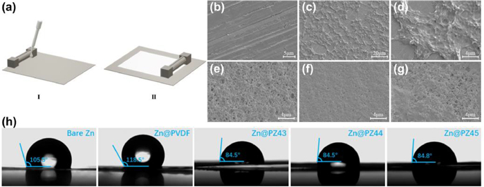
(a) Fabrication procedures of the Zn@PZs and Zn@PVDF. SEM images of (b) bare Zn, (c, d) Zn@PVDF, (e) Zn@PZ43, (f) Zn@PZ44 and (g) Zn@PZ45. (h) Optical images of the contact angles of different anodes respectively.

In the past two decades, lithium-ion batteries (LIBs) are undoubtedly the most representative energy storage devices, which power most 3C electronic devices and electric vehicles. However, the explosion accidents happened recently, which are related to organic electrolytes, have aroused growing concern about the safety issues of LIBs [1,2]. Aqueous batteries (ABs) based on non-flammable and high ion conductivity aqueous electrolytes are attracting increasing attention as a safer alternative. Besides, ABs are cost effective, more environmentally friendly and have higher tolerance against production environment and mechanical mishandling, compared with organic electrolyte batteries [3–5].
To date, various types of ABs with different ion carriers (e.g., Li+ [6], Na+ [7], K+ [8], Zn2+, Mg2+ [9] and Al3+ [10]) have been studied. Among them, the rechargeable zinc-ion batteries (ZIBs) proposed by Kang et al. in 2012 [11], have gained the greatest attention because of many merits of Zn metal [12,13], including a proper reduction potential (−0.76 V vs. standard hydrogen electrode), high theoretical specific capacity (volumetric capacity of 5855 mAh/cm3 and gravimetric capacity of 820 mAh/g), low cost, environmental benignity and high abundance. Particularly, ZIBs can deliver a higher energy density due to the intrinsic hostless feature of Zn metal that can minimize the weight of anode.
In ZIBs, a mildly acidic electrolyte is commonly used while Zn metal is used as anode directly. Although the plating/stripping of Zn metal is more reversible than in alkaline electrolyte [14,15], there are still some critical issues due to the absence of a protective solid electrolyte interphase (SEI) in a conventional system [16–18]. These issues, including dendrites formation and continuous side reactions (hydrogen evolution reaction and corrosion), render a poor cycling performance or even a rapid failure of a cell [19].
To stabilize the Zn anode, extensive efforts have been devoted, such as optimization of the electrode structure and construction of protective layers. Generally, building an artificial functional layer via an in situ chemical pretreatment [20–23] or the ex-situ coating process has been proved to be a simple and effective strategy. It is demonstrated that carbon materials (such as nitrogen-doped carbon [24], active carbon [25], graphite [26,27]) and MXene [28], can effectively suppress Zn dendrites growth by facilitating homogeneous current distribution and confining the Zn deposition. However, these conductive interface layers cannot significantly block the side reactions because the electrons can still get through and encounter water molecules. This problem may be solved by using non-conductive materials [29] instead. Metal organic framework (MOF) [30,31] and covalent organic framework (COF) [32] materials are suitable ones because of their high ionic conductivity and low electronic conductivity. But the complex fabrication processes of these materials make these solutions questionable for practical applications. Non-conductive polymer seems a better choice since they can provide both good ionic conductivity and acceptable mechanical strength with scalable ways, which can allow Zn2+ transport but block water encounter Zn surface [33–36]. Despite this, these layers may suffer from crack and/or peeling off during the repeated stripping/plating since they are not self-reparable as that of in situ formed SEI [16], or self-regulating as that of dynamic interphase [37] in repeated cycles. But as is well-known, the formation of in situ formed SEI consumes electrons and electrolytes in the first few cycles [16,38], during which the anodes are lack of protection. Therefore, it is highly appreciated to construct a SEI that is self-reparable with an artificial way.
Although the zinc hydroxide sulfate hydrate [Zn4SO4(OH)6·xH2O, ZHS] generated on Zn anode during the cycles is Zn2+-conducting [18], it is usually regarded as a by-product layer rather than a SEI layer since it is piled up loosely on the surface with plenty of open space, and then cannot terminate the side reactions [20,39]. Herein, a compact and self-repairing solid electrolyte interface (SEI) film, as labeled the PVDF-Zn(TFSI)2-ZHS coating [the PVDF and Zn(TFSI)2 are polyvinylidene fluoride and zinc bis(trifluoromethanesulfonyl)imide, respectively] was designed and fabricated. In this SEI layer, the in situ generated ZHS turns into a beneficial ingredient. Specifically, a PVDF-based composite layer containing Zn(TFSI)2 was firstly coated via a simple doctor blade method. This insulated and porous layer can partly isolate Zn from the electrolyte and homogenize Zn2+ flux, thus effectively suppress side reactions and dendrites growth. The gradually generated ZHS was subsequently adhered by PVDF to form the PVDF-Zn(TFSI)2-ZHS coating layer without obvious pores, allowing a rapid Zn2+ diffusion. As the intermediate layer transforms into a more stable polymer-inorganic composite layer, the artificial SEI layer is self-repairing, preventing the dendrites and side reactions even if the original layer cracks during the repeated Zn plating/stripping cycles. Therefore, this SEI perfectly conforms to the general criteria (chemically stable, dense and feature high Zn2+ conductivity, low electronic conductivity, and high mechanical flexibility) for a protective SEI layer summarized by Qiao et al. [40]. Benefiting from this hybrid SEI layer, a symmetric cell exhibits a high cycling stability over 750 h at 2.0 mA/cm2 and 2.0 mAh/cm2, and meanwhile, a full-cell, coupled with K+ pre-intercalation α-MnO2 (KMO) cathode [41], displays excellent rate performance, stable coulombic efficiency and a long cycle life.
The fabrication procedures of the PVDF containing Zn(TFSI)2- coated Zn foils (Zn@PZs) were illustrated in Supporting information. Briefly, PVDF and Zn(TFSI)2 were mixed in the N, N-dimethylformamide (DMF) solvent to obtain a homogeneous mixture. Then, a doctor blade method was utilized to cast the as-prepared mixture onto the previously polished Zn foil (Fig. 1a). Specifically, the coating layers of 10 µm thickness with different mass ratios (mPVDF: mZn(TFSI)2 = 4:3, 4:4 and 4:5) were prepared, which were denoted as Zn@PZ43, Zn@PZ44 and Zn@PZ45, respectively, to study the effect of the amount of Zn(TFSI)2 on the coating layer. In addition, the previously polished Zn foil coated by pure PVDF (Zn@PVDF) was also prepared for comparison.
The bare and modified Zn foils were firstly characterized by X-ray diffraction (XRD) (Fig. S1 in Supporting information), and all XRD patterns clearly show the characteristic peaks of metal Zn (PDF#87–0713). However, the characteristic peaks of the coating layers were not detected, suggesting that the coating layer is hard to identify by XRD, which may be ascribed to the extremely thin thickness and/or their amorphous state. The XRD patterns of the corresponding polymer films (Fig. S2 in Supporting information) indicated the crystalline structure of powder PVDF has been obviously decreased by the assistant of the Zn(TFSI)2, which can increase their ion conductivity [42]. SEM images show completely different morphologies for the polished Zn foil and the coated ones (Figs. 1b-g), in which the polished bare Zn shows a dense surface with many scratches (Fig. 1b), and the Zn@PZs samples exhibit fluffy, porous and cross-linked polymer-based surfaces (Figs. 1e-g). However, the Zn@PVDF sample displays an unconnected coating structure with plenty of open space, resulting in the partly exposed Zn foil (Figs. 1c and d). These results indicate that the introduction of Zn(TFSI)2 into the PVDF polymer makes more uniform dispersion of PVDF-based coating layer, providing a better covering layer to isolate the water molecule from the Zn surface in a ZIBs.
The hydrophilicity of electrode is a crucial factor that influences the distribution and electrodeposition of Zn2+ [33,36], which was evaluated at ambient temperature with pure water. As shown in Fig. 1h, the contact angles of bare Zn and Zn@PVDF were 105.5° and 118.5°, respectively, indicating their hydrophobicity. Compared with them, the Zn@PZs samples exhibited smaller contact angels with ~84.5°, showing significantly enhanced hydrophilicity. The enhancement of the hydrophilicity may be ascribed to the microchannels constructed in the PVDF matrix due to the introduction of Zn(TFSI)2 (Figs. 1e-g). The introduction of Zn(TFSI)2 in the PVDF matrix is conducive to the uniform distribution of electrolyte and ion transport via the abundant tunnels, and thus suppressing the growth of dendrites in the subsequently assembled ZIBs.
To evaluate the practical effect of the coating layers, the electrochemical performances of symmetrical cells assembled by the various Zn-based electrodes were tested under commonly used current density and areal capacity conditions (2.0 mA/cm2 with 2.0 mAh/cm2). As shown in Fig. 2a, an irregularly fluctuating of the polarization voltage appeared in the cell assembled by the bare Zn electrodes after 72 h, which is ascribed to a dendrite-induced short circuit [40]. Meanwhile, the cells prepared by the respective Zn@PZ43 and Zn@PVDF electrodes only operate for ~100 h before short circuiting. In contrast, the cells assembled by the Zn@PZ44 and Zn@PZ45 electrodes display obviously enhanced cycling performance, with ~800 and 550 h, respectively. The enhanced cycling life is related to the increased nucleation overpotential and smaller concentration overpotential, as analyzed in Fig. 2b. Take the Zn@PZ44 as an example, the voltage profiles divided into three parts (plateau overpotential, nucleation overpotential and concentration overpotential) [43,44]. The relationship between the critical Zn nucleus radius (rcrit) and nucleation overpotential (NOP) obeys the following relation:
|
|
(1) |
where γ is the surface energy of the Zn-electrolyte interface, Vm is the molar volume of Zn, F is Faraday's constant, and η is the NOP. The Zn@PZs-based cells have larger nucleation overpotentials than that of the bare Zn-based and Zn@PVDF-based cells, respectively. This increased overpotential provides a sufficient driving force for the nucleation and growth processes with finer nuclei, which is similar to the brightener mechanism involved in the electroplating field, leading to dense and flat electrodeposition [34]. Besides, it is obviously found that the Zn@PZ44-based cell has the smallest concentration overpotential among the Zn@PZs-based cells, indicating a better ion transport, which is helpful for dendrites-free plating [44].
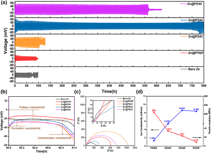
The significant difference indicates that the mass ratio of the PVDF and Zn(TFSI)2 plays an important effect on the cycle performance. It is indicated that the Zn@PZ44 electrode displays the most abundant and uniform nanopores in the surface (Fig. 1f), which can facilitate the transportation of Zn2+. These results are further confirmed by the EIS results achieved from their corresponding symmetric cells. As shown in the inserted Fig. 2c, each EIS spectrum of the Zn@PZs symmetric cell displays an incomplete semicircle in high frequency area, which is assigned to the SEI resistance (RSEI) [18], resulting from the artificial SEI film. Although the Zn@PZ44-based symmetric cell exhibits the highest RSEI, it shows the lowest charge transfer impedance (Rct). This reduced interfacial impedance is due to the accelerated ion kinetics. The Rct of Zn@PZ44-based symmetric cell is larger than that of Zn-based symmetric cell, which may be ascribed to the smaller effective electrode areas due to the coating [45]. Also, this result may be related with the balance between ion conductivity and mechanical strength of the polymer coating. The ionic conductivities of the coating layers with different mass ratios were evaluated by their corresponding EIS (Fig. S3 in Supporting information). As shown in Fig. 2d, the ionic conductivity of the PZ43F coating is 5.432 mS/cm, which is approximately three times higher than that of the PZ40F, indicating the significant improvement because of the introduction of Zn(TFSI)2 in the coating. With the increase of the content of Zn(TFSI)2, a high value of 8.635 mS/cm is obtained for the PZ44F coating. However, the ionic conductivity of the PZ45F coating is slightly lower than that of the PZ44F coating, which indicates the ionic conductivity has no further improvement when the Zn(TFSI)2 was saturated. Despite the similar ion conductivity with Zn@PZ44, the larger Rct of Zn@PZ45 can be attributed to the smaller effective area of the electrode and the hindrance of electron transfer, which can be further confirmed by the larger electrochemical polarization (plateau overpotential) of Zn@PZ45 shown in Fig. 2b. In contrast, the mechanical strength of the coating layers would be decreased with the increase in content of Zn(TFSI)2 owing to the brittle "salt-like structure" [46]. As shown in Fig. 2d and Fig. S4 (Supporting information), the PZ43F has the highest tensile modulus, while the PZ45F has the lowest one. Based on the above-mentioned facts, the PZ44F coating is the ideal coating with the best balance between the ionic conductivity and mechanical strength.
As mentioned above, the cycling life of the Zn@PZ44 cell at 2 mA/cm2 with 2 mAh/cm2 is about 10 times longer than that of the bare Zn cell. To further evaluate the cycling performance and structure stability, long-term galvanostatic cycling of the symmetric cells assembled by the bare Zn and Zn@PZ44 electrodes, respectively, at various current densities with distinct areal capacities were examined. A stable cycling of 300 h can be realized by the Zn@PZ44 symmetric cell even the current density and areal capacity were increased to 5.0 mA/cm2 and 5.0 mAh/cm2, while the bare Zn symmetric cell exhibited a sudden voltage drop only after ~80 h (Fig. S5 in Supporting information). Table S1 (Supporting information) shows the comparison of electrochemical performances of Zn-based symmetric cells, and it indicates that our assembled symmetric cell using the Zn@PZ44 electrode exhibits an advanced performance among the state-of-the-art Zn-based symmetric cells, especially in terms of long-term stability at high current density and areal capacity. Such an excellent electrochemical stability is mainly attributed to the critical synergistic roles of high ionic conductivity, good mechanical strength and hydrophilicity resulted from the optimized coating layer. To elucidate the working mechanism, relative characterizations and studies were further conducted.
The corrosion current density (icorr) is a direct factor in evaluating the rate of corrosion side reaction [47]. Thus, the inhibition effect of coating layer on the Zn corrosion has been studied by Tafel plots (Fig. 3a). With the protection of the coating, the icorr of the Zn@PZ44 electrode (0.70 mA/cm2) is lower than that of the bare Zn electrode (0.78 mA/cm2), indicating a lower rate of corrosion [21,48]. Fig. 3b shows the EIS spectra of the Zn@PZ44//Zn@PZ44 symmetric cells after different cycles. Before the 20th cycle, the Rct value changed continuously with the cycle number, which be indicative of a coordinated interface layer. It is found that it finally stabilized after 30 cycles, demonstrating a stable SEI layer formed on the electrode surface [18]. The morphology of the bare Zn electrode in the symmetric cell after 30 cycles (2.0 mA/cm2, 2.0 mAh/cm2) exhibited an extraordinarily rough surface with many flake-like protrusions and corrosion pots chaotically distributed (Figs. 3d-f). In contrast, the Zn@PZ44 electrode exhibited a relatively flat surface with dense morphology (Figs. 3g-i), which affords the chance to the Zn@PZ44 symmetric cell maintains a long cycle life. The high magnification SEM image (Fig. S6 in Supporting information) of the cycled Zn@PZ44 electrode indicated some small fragments were interspersed between the polymer blocks. The energy dispersive spectroscopy (EDS) mappings of the small fragment contain Zn, S and O elements, suggesting the generation of a new phase. Subsequent XRD patterns of the cycled bare Zn and Zn@PZ44 electrodes (Fig. S7 in Supporting information) indicated that the generated fragment was Zn4SO4(OH)6·xH2O (ZHS, PDF#44–0673). Also, it is noteworthy that the signal of ZHS is much stronger than that of metal Zn (PDF#87–0713) for the Zn@PZ44 electrode, indicating ZHS may be the main phase on the surface instead. ZHS is commonly regarded as harmful by-product rather than an advantageous SEI layer since it is piled up loosely on the electrode surface with plenty of open space, and it thus cannot isolate the Zn anode from the electrolyte and subsequently terminate the side reactions [20,39]. However, the in situ formed ZHS on the surface of the Zn@PZ44 electrode was adhered by PVDF without any open space to form a relatively flat surface with dense morphology, which can effectively suppress the side reaction and protect the Zn anode. According to the Tafel plots displayed in Fig. 3c, the icorr (0.23 mA/cm2) of the Zn@PZ44 electrode after 30 cycles is much lower than that (0. 86 mA/cm2) of the cycled bare Zn electrode. It is thus inferred that the as-formed coating layer on the electrode surface can also effectively suppress the further corrosion of Zn. And it is proved that ZHS is electronically insulating and highly ionic conductive [18], which can also provide a rapid Zn2+ transfer in the PVDF matrix. Meanwhile, the in-situ formation of ZHS is induced by a reaction of Zn2+, SO42− and OH− stemming from the contact between Zn and electrolyte, which in-turn terminates the hydrogen evolution reaction (HER) and Zn corrosion via the isolation of Zn from the electrolyte. In other words, the formation of ZHS will begin when the original layer cracks and Zn exposes to the electrolyte, and then will self-terminate when the coating layer recovers. Thus, a self-repairing polymer-inorganic composite coating composed of PVDF, Zn(TFSI)2 and ZHS was generated.
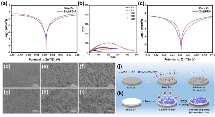
Given the above-presented results, the Zn stripping/plating possible mechanism without/with the presence of the coating is schematically illustrated in Figs. 3j and k, respectively. The bare Zn anode without any protection suffers from HER, corrosion and dendrite growth. In contrast, the electrically insulated and porous coating can partly isolate the Zn anode from the electrolyte and homogenize Zn2+ flux, thus effectively suppresses side reactions and dendrites growth. After a few cycles, ZHS will be gradually generated in the surface of the Zn@PZ44 electrode and be adhered by PVDF, forming a compact PVDF-Zn(TFSI)2-ZHS layer. ZHS is of electronical insulation and high ionic conductivity, which can further isolate the Zn from the electrolyte and allow a rapid Zn2+ transfer. Because the formation of ZHS is self-adjusting, a self-repairing polymer-inorganic composite SEI layer can be achieved during the cycles. Herein, the combination of a stable artificial composited layer and the self-adjusting ZHS to in-situ generate a SEI film perfectly conforms to the general criteria for a protective SEI layer design [40].
To further evaluate the positive effect of the PVDF-based coating, the Zn@PZ44//Cu@PZ44 and bare Zn//Cu cells were fabricated and tested with a plating capacity of 2.0 mAh/cm2 and a stripping potential cutoff of 0.6 V at 2.0 mA/cm2, respectively. After 30 cycles, the Zn successfully deposited on the surface of the Cu current collector electrodes, as demonstrated by the XRD patterns shown in Fig. S8 (Supporting information). The surface morphologies of both Cu-based electrodes after the Zn deposition shown in Fig. S9a (Supporting information) indicated an uneven and porous interface, with many flakes and irregular needle-like Zn dendrites on the surface of the bare Cu electrode (Fig. S9b in Supporting information). In contrast, the surface of the Cu@PZ44 electrode is smooth and dense, with some flakes adhered on the PVDF matrix. The coulombic efficiency (CE) of Zn stripping/plating is one of the important parameters for benchmarking the efficiency of ZIBs. A low CE is related to the irreversible electrochemical reactions such as HER, the formation of irreversible Zn-containing by-products and "dead" metallic Zn0 [40]. As shown in Fig. 4a, the bare Zn//Cu cell displays a fluctuating CE after 35 cycles and a soft short circuit after 50 cycles. However, the Zn@PZ44//Cu@PZ44 cell can deliver a stable CE during the repeated cycles, and with a high value of 99.24% at the 100th cycle. Their corresponding voltage-capacity curves are presented in Figs. S10 and S11 (Supporting information), respectively. It is worth pointing out that the CEs of the Cu@PZ44//Zn@PZ44 cell during the initial few cycles are lower than those of the bare Cu//Zn cell, which originates from the extra formation of ZHS in PVDF-Zn(TFSI)2-ZHS layer. The stable CE after 30 cycles is attributed to the in-situ formed stable interface, which was verified the EIS results shown in Fig. 3b.
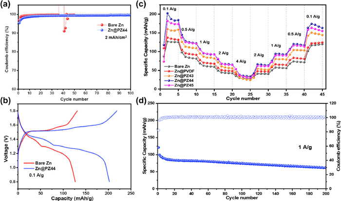
Fig. 4b presents the discharge-charge curves of the Zn//KMO and Zn@PZ44//KMO cells at 0.1 A/g. The discharge curves of both cells display two voltage plateaus at ~1.4 and ~1.2 V, respectively, indicating the Zn2+/H+ insertion/extraction [41,49]. The voltage hysteresis between the charge and discharge curves of the Zn@PZ44//KMO cells is smaller than that of the Zn//KMO cell, indicating a better interface and enhanced reaction kinetic due to the porous and more hydrophilic coating and the less of side reactions [50]. The rate performance of full cells assembled with five different anodes and KMO cathode were investigated (Fig. 4c). The Zn//KMO cell achieved specific capacities of 127.0, 98.3, 68.8, 49.4 and 35.3 mAh/g at 0.1, 0.5, 1, 2 and 4 A/g. respectively, which displayed the worst performance. In contrast, the Zn@PZ44//KMO cell exhibited specific capacities of 202.5, 144.9, 105.8, 80.9 and 53.7 mAh/g at identical current densities, respectively, demonstrating a superior rate performance than other four control groups. When the current density generally reverts to 0.1 A/g, the Zn@PZ44//KMO cell still maintains the highest specific capacity than that of the others. The corresponding galvanostatic charge/discharge (GCD) curves of five cells from 0.1 A/g to 4.0 A/g are presented in Figs. S12-S16 (Supporting information), respectively. The long-term cycling stability of the Zn@PZ44//KMO cell at 1.0 A/g (after 5 cycles at 0.1 A/g) shown in Fig. 4d, indicated that it displayed acceptable cycling stability, with a capacity retention of 60.9% after 200 cycles. Based on these above-mentioned results, it is suggested that the PZ44 coating and its derivative PVDF-Zn(TFSI)2-ZHS coating could simultaneously improve the rate performance, cycling stability and CE of a ZIB.
In summary, a self-repairing PVDF-Zn(TFSI)2-ZHS polymer-inorganic composite coating was designed and generated to provide an effective protection for Zn anode during cycling. The experimental results demonstrated that the in-situ formed SEI layer can isolate Zn from electrolyte and homogenize the Zn2+ flux, thus effectively suppresses dendrites growth and side reactions. As a result, the symmetric cell assembled by the Zn@PZ44 electrode delivers ultralong lifespan of ~800 h at 2.0 mA/cm2 with 2.0 mAh/cm2. Furthermore, the assembled Zn@PZ44//KMO full cell exhibits excellent rate performance, stable CE, and a long cycle life. The approach of designing a self-repairing SEI layer may provide a novel and feasible way for stabilizing the Zn anode for high performance ZIBs, which may contribute to constructing advanced protective layer for developing high-performance metal ion batteries.
The authors declare no conflict of interest.
This work was supported by the National Natural Science Foundation of Guangdong Province (No. 2022A1515010173), the National Natural Science Foundation of China (No. 22178125) and the 111 Project (No. B20003).
Supplementary material associated with this article can be found, in the online version, at doi:
J. Wang, Y. Yang, Y. Zhang, et al., Energy Storage Mater. 35 (2021) 19–46. doi: 10.1016/j.ensm.2020.10.027
Z. Yi, G. Chen, F. Hou, et al., Adv. Energy Mater. 11 (2021) 2003065. doi: 10.1002/aenm.202003065
D. Chao, W. Zhou, F. Xie, et al., Sci. Adv. 6 (2020) 4098. doi: 10.1126/sciadv.aba4098
Z. Pan, X. Liu, J. Yang, et al., Adv. Energy Mater. 11 (2021) 2100608. doi: 10.1002/aenm.202100608
H. Jia, Z. Wang, B. Tawiah, et al., Nano Energy 70 (2020) 104523. doi: 10.1016/j.nanoen.2020.104523
K. Xu, Carbon Energy 3 (2021) 721–751. doi: 10.1002/cey2.106
D. Bin, F. Wang, A.G. T. amirat, et al., Adv. Energy Mater. 8 (2018) 1703008. doi: 10.1002/aenm.201703008
L. Jiang, Y. Lu, C. Zhao, et al., Nat. Energy 4 (2019) 495–503. doi: 10.1038/s41560-019-0388-0
F. Wang, X. Fan, T. Gao, et al., ACS Cent. Sci. 3 (2017) 1121–1128. doi: 10.1021/acscentsci.7b00361
D. Yuan, J. Zhao, W. Manalastas, et al., Nano Mater. Sci. 2 (2020) 248–263. doi: 10.1016/j.nanoms.2019.11.001
C. Xu, B. Li, H. Du, et al., Angew. Chem. Int. Ed. 51 (2012) 933–935. doi: 10.1002/anie.201106307
W. Du, E.H. A. ng, Y. Yang, et al., Energy Environ. Sci. 13 (2020) 3330–3360. doi: 10.1039/d0ee02079f
T. Wang, C. Li, X. Xie, et al., ACS Nano 14 (2020) 16321–16347. doi: 10.1021/acsnano.0c07041
J. Hao, X. Li, X. Zeng, et al., Energy Environ. Sci. 13 (2020) 3917–3949. doi: 10.1039/d0ee02162h
P. Zou, R. Zhang, L. Yao, et al., Adv. Energy Mater. 11 (2021) 2100982. doi: 10.1002/aenm.202100982
D. Li, L. Cao, T. Deng, et al., Angew. Chem. Int. Ed. 60 (2021) 13035–13041. doi: 10.1002/anie.202103390
X. Zeng, J. Mao, J. Hao, et al., Adv. Mater. 33 (2021) 2007416. doi: 10.1002/adma.202007416
W. Yuan, G. Ma, X. Nie, et al., Biochem. Eng. J. 431 (2022) 134076.
C. Li, X. Xie, S. Liang, et al., Energy Environ. Mater. 3 (2020) 146–159. doi: 10.1002/eem2.12067
J. Hao, B. Li, X. Li, et al., Adv. Mater. 32 (2020) 2003021. doi: 10.1002/adma.202003021
Y. Yang, C. Liu, Z. Lv, et al., Adv. Mater. 33 (2021) 2007388. doi: 10.1002/adma.202007388
L. Ma, Q. Li, Y. Ying, et al., Adv. Mater. 33 (2021) 2007406. doi: 10.1002/adma.202007406
M. Wang, Y. Meng, K. Li, et al., eScience 2 (2022) 509–517. doi: 10.1016/j.esci.2022.04.003
C. Wu, K. Xie, K. Ren, et al., Dalton Trans. 49 (2020) 17629–17634. doi: 10.1039/d0dt03459b
W. Li, K. Wang, M. Zhou, et al., ACS Appl. Mater. Interfaces 10 (2018) 22059–22066. doi: 10.1021/acsami.8b04085
Z. Li, L. Wu, S. Dong, et al., Adv. Funct. Mater. 31 (2021) 2006495. doi: 10.1002/adfm.202006495
A. Wang, W. Zhou, A. Huang, et al., J. Colloid Interface Sci. 577 (2020) 256–264. doi: 10.1016/j.jcis.2020.05.102
N. Zhang, S. Huang, Z. Yuan, et al., Angew. Chem. Int. Ed. 60 (2021) 2861–2865. doi: 10.1002/anie.202012322
C. Xie, Q. Zhang, Z. Yang, et al., Chin. Chem. Lett. 33 (2022) 2653–2657. doi: 10.1016/j.cclet.2021.09.083
R. Yuksel, O. Buyukcakir, W.K. S. eong, et al., Adv. Energy Mater. 10 (2020) 1904215. doi: 10.1002/aenm.201904215
X. Pu, B. Jiang, X. Wang, et al., Nano-Micro Lett. 12 (2020) 152. doi: 10.1007/s40820-020-00487-1
Z. Zhao, R. Wang, C. Peng, et al., Nat. Commun. 12 (2021) 6606. doi: 10.1038/s41467-021-26947-9
S.H. P. ark, S.Y. B. yeon, J.H. Park, et al., ACS Energy Lett. 6 (2021) 3078–3085. doi: 10.1021/acsenergylett.1c01521
Z. Zhao, J. Zhao, Z. Hu, et al., Energy Environ. Sci. 12 (2019) 1938–1949. doi: 10.1039/c9ee00596j
F. Zhang, C. Wang, J. Pan, et al., Mater. Today Energy 17 (2020) 100443. doi: 10.1016/j.mtener.2020.100443
P. Chen, X. Yuan, Y. Xia, et al., Adv. Sci. 8 (2021) 2100309. doi: 10.1002/advs.202100309
W. Zhang, Q. Zhao, Y. Hou, et al., Sci. Adv. 7 (2021) eabl3752. doi: 10.1126/sciadv.abl3752
Y. Chu, S. Zhang, S. Wu, et al., Energy Environ. Sci. 14 (2021) 3609–3620. doi: 10.1039/d1ee00308a
J. Hao, X. Li, S. Zhang, et al., Adv. Funct. Mater. 30 (2020) 2001263. doi: 10.1002/adfm.202001263
L. Yuan, J. Hao, C. -. C. Kao, et al., Energy Environ. Sci. 14 (2021) 5669–5689. doi: 10.1039/d1ee02021h
K. Han, F.Q. A. n, F.S. Y. an, et al., J. Mater. Chem. A 9 (2021) 15637–15647. doi: 10.1039/d1ta03994f
H. Fan, M. Wang, Y. Yin, et al., Energy Storage Mater. 49 (2022) 380–389. doi: 10.1016/j.ensm.2022.04.031
T. Zhang, Y. Tang, S. Guo, et al., Energy Environ. Sci. 13 (2020) 4625–4665. doi: 10.1039/d0ee02620d
Y. Zhou, J. Xia, J. Di, et al., Adv. Energy Mater. (2023) 2203165. doi: 10.1002/aenm.202203165
A.R. H. arris, P. Carter, R. Cowan, et al., ChemElectroChem 8 (2021) 1078–1090. doi: 10.1002/celc.202001574
F. Mo, Z. Chen, G. Liang, et al., Adv. Energy Mater. 10 (2020) 2000035. doi: 10.1002/aenm.202000035
H. Chen, Z. Guo, H. Wang, et al., Energy Storage Mater. 54 (2023) 563–569. doi: 10.1016/j.ensm.2022.11.013
Z. Li, Z. Gong, X. Wu, et al., Chin. Chem. Lett. 33 (2022) 3936–3940. doi: 10.1016/j.cclet.2021.11.015
W. Sun, F. Wang, S. Hou, et al., J. Am. Chem. Soc. 139 (2017) 9775–9778. doi: 10.1021/jacs.7b04471
K. Han, Z. Wang, F. An, et al., ACS Appl. Mater. Interfaces 14 (2022) 4316–4325. doi: 10.1021/acsami.1c22504

Figure 1 (a) Fabrication procedures of the Zn@PZs and Zn@PVDF. SEM images of (b) bare Zn, (c, d) Zn@PVDF, (e) Zn@PZ43, (f) Zn@PZ44 and (g) Zn@PZ45. (h) Optical images of the contact angles of different anodes respectively.

Figure 2 (a) Long-term galvanostatic cycling performance of symmetric cells at 2.0 mA/cm2 with the capacity of 2.0 mAh/cm2. (b) The enlarged voltage profiles of the galvanostatic cycling. (c) EIS spectra of the Zn symmetric cells before cycling at room temperature. (d) The calculated ionic conductivity and tensile modulus of different coating layers.

Figure 3 Tafel plots for the bare Zn and Zn@PZ44 symmetric cells (a) before and (c) after 30 cycles at a scan rate of 1 mV/s. (b) EIS spectra of Zn@PZ44//Zn@PZ44 symmetric cell during cycling. SEM images of (d-f) bare Zn and (g-i) Zn@PZ44 electrode after 30 cycles. Schematic illustration of the surface chemistry on Zn electrodes (j) without and (k) with coating.

Figure 4 (a) Coulombic efficiencies (CEs) of the bare Zn//Cu and Zn@PZ44//Cu@PZ44 cells. (b) Discharge-charge curves of the Zn//KMO and Zn@PZ44//KMO cells at 0.1 A/g. (c) Rate performance of the Zn//KMO, Zn@PVDF//KMO, Zn@PZ43//KMO Zn@PZ44//KMO and Zn@PZ45//KMO cells, and (d) long-term cycling performances and CEs of the Zn@PZ44//KMO cell at 1.0 A/g after several activation at 0.1 A/g.

 扫一扫看文章

扫一扫关注我们
 DownLoad:
 下载:
下载: