Figure 1.
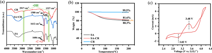
(a) Infrared spectra of CR, SA, SA-CR. (b) Thermogravimetric analysis results of SA-CR and CR. (c) CV curve of SA-CR cathode||Li anode cell at a scan rate of 0.1 mV/s and the range of 2.5–4.2 V.
Conductive composite binder for recyclable LiFePO4 cathode
Wendi Dou , Guangying Wan , Tiefeng Liu , Lin Han , Wu Zhang , Chuang Sun , Rensheng Song , Jianhui Zheng , Yujing Liu , Xinyong Tao

Presently, large-scale electrochemical energy storage (EES) has been substantially developed to deal with the power fluctuations from renewable energy and smart grids [1,2]. However, the demand for massive production of rechargeable batteries also has arisen the critical issues regarding battery sustainability [3–5]. Creating a closed-loop circulation scenario for key battery materials is believed as an ideal solution, not only efficiently addressing the ecological threaten of spent batteries but also enabling the sustainable supply of key resource [6–10]. Among the field of lithium ion batteries (LIBs), LiFePO4 (LFP)-based LIBs have been considered as the most viable candidate for EES due to the affordable manufacturing cost and sufficient cycling lifespan. As such, research efforts are ongoing to develop the underlying recycling technologies towards the LFP cathodes [11]. Electrochemical restoration of the LFP cathode has recently garnered much attention due to the low chemical/energy cost [12–14]. This is attributed to its inherent merits of neither destroying original crystal structure nor breaking down electroactive materials into elements states, in turn emphasizing Li supplement and crystalline restoration [11]. The subsequent challenges are how to obtain high-purity recycled LFP cathode for the succeeding electrochemical restoration.
In a typical process of electrode fabrication, the electroactive materials are initially mixed with conductive additive and polymeric binder in the solvent [15,16]. The electrode slurry is cast on the current collector. In the recycling process, the removal of conductive additive and polymeric binder must be correspondingly implemented [8]. The most representative binder is the polyvinylidene fluoride (PVDF), which is only eliminated by thermal treatment or soaking in organic solvents, both of which still lead to the subsequent gas emission and environmental threats [9]. Recently, the use of a reversible binder in sulfur electrodes has shown promise in separating electroactive materials in an environmentally-friendly and effective manner [17,18]. The drawback is the residue of conductive additives, which is regarded as the impurity for spent cathode [19]. The insulating properties of such single-component binders greatly limit the future application of LIBs. Therefore, the development of conductive binders instead of isolated binders and conductive additives is substantially emphasized because the electrode could be free of conductive additives [20]. Unfortunately, the existing synthesis of conductive binders usually involves complex coupling reactions and uses costly precursors [7]. It is highly desired to seek for the natural and nontoxic alternatives introduced into the binder network in a mild reaction process [21–24].
In this work, we propose the sodium alginate (SA) grafted by Congo Red (CR) to form copolymers as a water-soluble electrically conductive and mechanically robust composite binder (SA-CR) for LFP cathode. Unlike most other electrically conductive polymer binders, the procedure is straightforward and low-cost to prepare SA-CR binder. Without using conductive additives, the resultant LFP cathode based on SA-CR binder still exhibit stable cycling performance. The copolymer whose composition was filled with a mixture of SA and CR at a 3:1 mass ratio showed the best cell performance, due to the well-balanced electrical conductivity and mechanical properties. After 100 cycles at 1 C, the specific capacity of 118.8 mAh/g was still maintained accompanied with the retention rate of 92.1%. This is attributed to that the introduction of CR into composite binder allows continuous and homogenous conducting bridges throughout the electrode. Furthermore, due to no use of conductive additives, the LFP cathode could readily be recycled by soaking in the water. The separated LFP cathode exhibits high purity for the succeeding regeneration process. This work shed light on the possibility of exploring conductive water-soluble binder for recyclable LFP cathode.
The SA binder has been previously confirmed its effectiveness in bonding LFP cathode for stable cycling lifespan [25–28]. However, the SA is isolated. The role of conductive additives is needed to ensure fast electric transfer between electroactive materials and current collector. Subsequently, the SA is mixed with CR through a hydrothermal reaction process (Fig. S1 in Supporting information). The FT-IR spectra of the SA, CR and SA-CR samples are shown in Fig. 1a. The peaks observed at 2917 and 1327 cm−1 are considered to be the O—H stretching vibrations of the carboxyl group in SA. The peak appeared at 1606 cm−1 is the stretching vibration of C═O in -COO−. Compared with the infrared spectra of SA and CR, the N—H peak at 1580 cm−1 in the SA-CR spectra disappeared. In addition, the stretching vibration of C═O changed from a broad peak at 1606 cm−1 to a sharp peak at 1612 cm−1. These changes of these functional groups confirmed the formation of an amide bond between SA and CR.
The thermal stability of the SA, CR, SA-CR samples were investigated as shown in Fig. 1b. The thermal stability of CR maintains a mass retention rate of about 99.5% even if the temperature is raised to 200 ℃. In the range of 30-200 ℃, the thermal stability of SA-CR is significantly better than that of SA. The former maintains a retention rate of about 81.6%; the latter only maintains at 80.3%. Therefore, in the composite binder, the addition of CR improves the thermal stability of the overall binder, providing a good foundation for the preparation of stable electrodes. We measured the electrochemical performance of SA-CR using the pure SA-CR coated on Al foil as the cathode (Fig. 1c). The CV curve shows that SA-CR has a strong reduction peak, occurring at 3.02 V. The redox peak in the figure has good coincidence, indicating that the binder has extra capacity contribution to LFP during cycling.
To evaluate the effectiveness of SA-CR binder for the LFP cathode, we implement a series of electrochemical tests including galvanostatic charge–discharge, EIS and CV. As shown in Fig. 2a, the LFP cathode has higher initial discharge specific capacity (156.4 mAh/g) and coulombic efficiency (90.3%). In comparison, the initial discharge specific capacity and coulombic efficiency of the sodium alginate-acetylene black electrode (SA-AB) are 152.2 mAh/g and 88.1%, respectively. In the absence of the addition of conductive agents, the developed conductive polymer binder enables LFP to exhibit more advantageous performance. However, both a clear couple of redox peaks can be seen in two groups which is corresponding to the de-lithiation/lithiation process of the LFP cathode. Such an electrochemical behavior is equal to that of the LFP cathode simultaneously using the SA and AB. After 3 cycles of activation at 0.2 C, the Li||LFP-SA-CR and Li||LFP-SA-AB half-cells were performed at 1.0 C for the subsequent cycles. It can be clearly seen in Fig. 2b that the discharge capacity of LFP-SA-CR is larger than that of LFP-SA-AB in 100 cycles. The cycling stability of LFP-SA-CR electrode is more excellent. After 100 cycles, the specific capacity of 118.8 mAh/g was still maintained accompanied with the retention rate of 92.1% in the Li||LFP-SA-CR half-cell, while the LFP-SA-AB electrode just exhibits a specific capacity of 108.5 mAh/g. In addition, the average Coulombic efficiency for long-term cycling (4–100 cycles) is more stable in the LFP-SA-CR electrode than the LFP-SA-AB electrode. This indicates that the CEI on the surface of LFP-SA-CR electrode is relatively more stable. Rate capability of the SA-CR electrode was also conducted with a battery test system. As shown in Fig. S2 (Supporting information), the SA-CR electrode provides good rate property with discharge capacities of 131.4, 123.5, and 110.7 mAh/g at different current densities of 0.5, 1.0, and 2.0 C. Therefore, it has better long-term cycle performance.
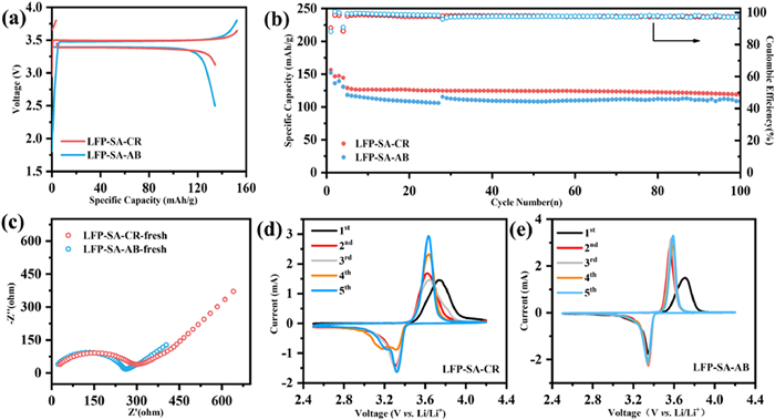
Subsequently, the electrode impedance test was performed (Fig. 2c). Due to the higher electronic conductivity of acetylene black, the LFP-SA-AB electrode exhibits a smaller Nyquist plot than the LFP-SA-CR in the fresh state. However, the two battery systems show similar Warburg diffusion resistance which is also an important reason for improving the electrochemical performance. As a result, such special binder is adequate to allow LFP to function to its full potential even in the absence of conductive agents. Also, Figs. 2d and e shows the CV profiles of LFP-SA-CR and LFP-SA-AB electrodes at a scan rate of 0.1 mV/s in a voltage window of 2.5–4.2 V (vs. Li/Li+). Well-defined redox peaks at 3.35 V and 3.62 V were observed for LFP-SA-CR and LFP-SA-AB electrodes, respectively, which are the typical redox peak of LFP cathode. The symmetry of the redox peaks suggests excellent reversibility of these electrode. Furthermore, an interesting phenomenon was also observed that there is a strong reduction peak occurring at 3.12 V in LFP-SA-CR||Li half-cell that may be assigned to the reduction of SA-CR.
In the process of preparing electrode slurry, the good wettability of binder solution for LFP is favor to make the efficient electrode fabrication and good dispersion of binder on LFP surface, eventually achieving good electrode performance. As shown in Fig. 3a, the contact angle between the two and the Al foil is similar, indicated that the use of this binder enables the slurry to adhere well to the current collector and there is no effect on wettability with Al foil.
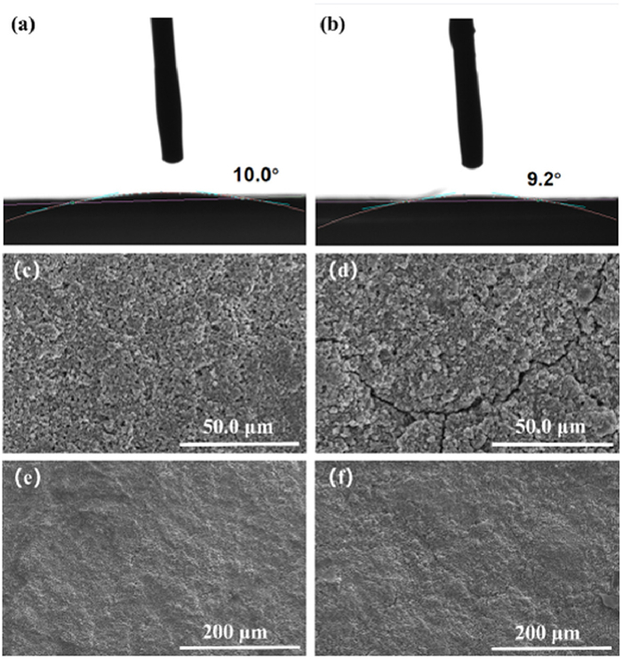
Figs. 3c–f show the SEM images of the LFP-SA-CR and LFP-SA-AB cathodes after cycling. After 50 cycles, wide and deep cracks can be clearly seen on the surface of the LFP-SA-AB electrode, while almost no cracks can be seen on the electrode surface after cycling on the surface of the LFP-SA-CR electrode. This phenomenon also corresponds to the performance of its long-cycle performance. The surface cracks of the LFP-SA-AB cathode are large, so that the surface CEI is continuously generated, and the limited electrolyte and Li+ are consumed, resulting in a rapid capacity decline. The SA-CR binder has the cross-linked network to improve the mechanical properties of the electrode, and make it have a relatively stable long-cycle performance.
Previous works has shown that the electronic structure can be modulated by blending two organics with different energy levels [29]. For a deep insight into the essence of the superior electrochemical behavior of SA-CR, we verified molecular orbital energy levels of SA fragment and CR, respectively. The lowest unoccupied molecular orbital (LUMO) energy level represents the ability to gain electrons. Consequently, a lower LUMO energy level means a higher electron affinity. In Fig. 4a, the LUMO energy of CR is significantly lower than that of SA due to the presence of the strongly electron-withdrawing groups N═N. Therefore, during the charging process, the system with CR would prefer to obtain the electron from the electrode to form CR-Li and speed up the electron-accepting process [30].
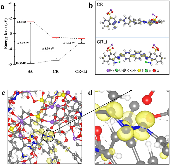
From the HOMO orbit diagram of CR and the partial charge density for electrons of SA-CR, it can be seen that the HOMO orbits (Fig. 4b(CR)) and the partial charge density near Fermi energy (−0.5 eV vs. Fermi energy) (Figs. 4c and d) are mainly concentrated in the vicinity of N═N, indicating there are active sites near N═N. Therefore, it is possible for lithium atoms to adsorb around N═N. Subsequently, we tried several different adsorption configurations and found that lithium had the lowest binding energy when it was adsorbed near three nitrogen atoms (Fig. 4b(CRLi)). It is worth noting that the HOMO-LUMO gap is significantly reduced (0.33 eV) by N-type doping following the adsorption of lithium, which may be an important reason for the improvement of electrical conductivity of SA-CR system [30,31].
Afterwards, we recycled the LFP cathode by soaking the electrode into the water. After the ultra-sonication treatment, the SA-CR binder is progressively dissolved in the water and corresponding the LFP powder is gradually detached from the Al foils, as shown in Fig. S2a (Supporting information). Due to the binder fully dissolved in the water and no use of conductive additives, the LFP cathode is separated through a simple filtration process. After several washing treatments, the recovered LFP cathode material powder is clean and free of impurities, and seemingly has no obvious difference from fresh LFP powder (Figs. S3b, S4 and S5 in Supporting information). Normally, these recycled LFP cathode suffers from the Li loss in crystal structure and carbon coating crack on material surface [8]. As a result, the electrochemical performance of recycled LFP is not as well as that of fresh LFP (Fig. S6 in Supporting information). Subsequently, structural repairing may be implemented for electrochemical restoration.
In conclusion, we have investigated electrochemical performance of LFP cathode based on SA-CR binder. Compared with the SA directly mixed with AB, the SA-CR binder can efficiently improve the integrity of the electrodes during cycling and facilitate the charge transfer at the interface. Not only does this dual combination provide excellent performance, but it also presents a reduced parameter space by eliminating the need to tailor the interaction between the active material and an additional conductive additive via a polymeric binder. This method demonstrates a promising approach to reduce the complexity of other electrode material recycling processes for high-energy LIBs.
The authors declare that they have no known competing financial interests or personal relationships that could have appeared to influence the work reported in this paper.
The authors acknowledge financial support by the National Key R&D Program of China (No. 2022YFB2502000), National Natural Science Foundation of China (Nos. 52225208, 52002352, U21A20174 and 52071295), Leading Innovative and Entrepreneur Team Introduction Program of Zhejiang (No. 2020R01002).
Supplementary material associated with this article can be found, in the online version, at doi:
T. Liu, Y. Zhang, Z. Jiang, et al., Energy Environ. Sci. 12 (2019) 1512–1533. doi: 10.1039/C8EE03727B
W. Zhang, X. Yang, J. Wang, et al., Small 19 (2023) 2207540. doi: 10.1002/smll.202207540
M. Zheng, H. Salim, T. Liu, et al., Energy Environ. Sci. 14 (2021) 5801–5815. doi: 10.1039/D1EE01812D
M. Cheng, T. Qu, J. Zi, et al., Nanotechnology 31 (2020) 425401. doi: 10.1088/1361-6528/aba059
S. Chang, M. Hou, B. Xu, et al., Adv. Funct. Mater. 31 (2021) 2011151. doi: 10.1002/adfm.202011151
M. Zheng, J. Wang, S. Qian, et al., ACS Sustain. Chem. Eng. 11 (2023) 4308–4316. doi: 10.1021/acssuschemeng.2c05124
X.X. Wu, J. Ma, J.X. Wang, et al., Glob. Challeng. 6 (2022) 2200067. doi: 10.1002/gch2.202200067
L. Wang, Y. Shen, Y. Liu, et al., Small Methods (2023) 2201658.
Y. Yang, E.G. Okonkwo, G. Huang, et al., Energy Storage Mater. 36 (2021) 186. doi: 10.1016/j.ensm.2020.12.019
J. Heelan, E. Gratz, Z. Zheng, et al., JOM 68 (2016) 2632–2638. doi: 10.1007/s11837-016-1994-y
M. Zhang, L. Wang, S. Wang, et al., Small Methods (2023) 2300125.
J. Diekmann, C. Hanisch, L. Frobose, et al., J. Electrochem. Soc. 164 (2017) A6184–A6191. doi: 10.1149/2.0271701jes
J. Neumann, M. Petranikova, M. Meeus, et al., Adv. Energy Mater. 12 (2022) 2102917. doi: 10.1002/aenm.202102917
F. Liang, Y. Sun, Y. Yuan, et al., Mater. Today 50 (2021) 418–441. doi: 10.1016/j.mattod.2021.03.013
Y. Hao, J. Shao, Y. Yuan, et al., Adv. Funct. Mater. 33 (2023) 2212692. doi: 10.1002/adfm.202212692
L. Ding, L. Wang, J. Gao, et al., Adv. Funct. Mater. (2023) 2301648.
H. Wang, G. Zhang, Y. Chen, et al., Chem. Eng. J. 452 (2023) 139128. doi: 10.1016/j.cej.2022.139128
Z. Liu, X. He, C. Fang, et al., Adv. Funct. Mater. 30 (2020) 2003605. doi: 10.1002/adfm.202003605
L. Gaines, Sustain. Mater. Technol. 17 (2018) e00068.
Z. Ju, H. Yuan, O. Sheng, et al., Small Sci. 1 (2021) 2100055. doi: 10.1002/smsc.202100055
Z. Gao, Y.Y. Zhang, N.N. Song, X.D. Li, Mater. Res. Lett. 5 (2017) 69–88. doi: 10.1080/21663831.2016.1250834
T.M. Higgins, S.H. Park, P.J. King, et al., ACS Nano 10 (2016) 3702–3713. doi: 10.1021/acsnano.6b00218
K.K. Rajeev, E. Kim, J. Nam, et al., Electrochim. Acta 333 (2020) 135532. doi: 10.1016/j.electacta.2019.135532
W. Dou, M. Zheng, W. Zhang, et al., Adv. Funct. Mater. (2023) 2305161.
J. He, H. Zhong, J. Wang, L. Zhang, J. Alloys Compd. 714 (2017) 409–418. doi: 10.1016/j.jallcom.2017.04.238
F. Bigoni, F. De Giorgio, F. Soavi, C. Arbizzani, J. Electrochem. Soc. 164 (2017) A6171. doi: 10.1149/2.0281701jes
M. Ling, J. Qiu, S. Li, et al., Nano Lett. 15 (2015) 4440–4447. doi: 10.1021/acs.nanolett.5b00795
Y. Ding, X. Zhong, C. Yuan, et al., ACS Appl. Mater. Interfaces 13 (2021) 20681–20688. doi: 10.1021/acsami.1c02995
X. -Y. Wang, Z. -D. Yu, Y. Lu, et al., Adv. Mater. 35 (2023) 2300634. doi: 10.1002/adma.202300634
Z. Ye, S. Xie, Z. Cao, et al., Energy Storage Mater. 37 (2021) 378–386. doi: 10.1016/j.ensm.2021.02.022
T.P. Kaloni, P.K. Giesbrecht, G. Schreckenbach, M.S. Freund, Chem. Mater. 29 (2017) 10248–10283. doi: 10.1021/acs.chemmater.7b03035

Figure 1 (a) Infrared spectra of CR, SA, SA-CR. (b) Thermogravimetric analysis results of SA-CR and CR. (c) CV curve of SA-CR cathode||Li anode cell at a scan rate of 0.1 mV/s and the range of 2.5–4.2 V.

Figure 2 (a) Initial charge/discharge profiles of different LFP cathodes at 0.2 C. (b) Cycle performance of different LFP cathodes at 1 C. (c) Electrochemical impedance spectroscopy (EIS) of fresh electrodes. CV curve of (d) the Li||LFP-SA-CR half-cell and (e) the Li||LFP-SA-AB half-cell at a scan rate of 0.1 mV/s and the range of 2.5–4.2 V.

Figure 3 (a) The contact angle of the SA-CR solution with LFP powder on aluminum foil. (b) The contact angle of the SA-AB solution with LFP powder on aluminum foil. (c, e) SEM images of the electrodes using SA-CR as binders after 50 cycles. (d, f) SEM images of electrodes using AB as binders after 50 cycles.

 扫一扫看文章

扫一扫关注我们
 DownLoad:
 下载:
下载:
