绿色双溶剂法制备高效稳定钙钛矿太阳能电池

朱晨溦 金一诺 张春虹 陈衡慧 陈劭添 付禹鸣 吴韫佳 孙伟海

引用本文: 朱晨溦, 金一诺, 张春虹, 陈衡慧, 陈劭添, 付禹鸣, 吴韫佳, 孙伟海. 绿色双溶剂法制备高效稳定钙钛矿太阳能电池[J]. 无机化学学报, 2023, 39(6): 1061-1071. doi: 10.11862/CJIC.2023.084 shu
Citation:  Chen-Wei ZHU, Yi-Nuo JIN, Chun-Hong ZHANG, Heng-Hui CHEN, Shao-Tian CHEN, Yu-Ming FU, Yun-Jia WU, Wei-Hai SUN. High-performance and stable perovskite solar cells prepared with a green bi-solvent method[J]. Chinese Journal of Inorganic Chemistry, 2023, 39(6): 1061-1071. doi: 10.11862/CJIC.2023.084 shu

绿色双溶剂法制备高效稳定钙钛矿太阳能电池

    通讯作者: 孙伟海, E-mail: sunweihai@hqu.edu.cn
  • 基金项目:

    国家自然科学基金 61804058

    华侨大学中青年教师科研提升资助计划 ZQN-706

摘要: 采用毒性小、环境友好的乙二醇甲醚(ethylene glycol monomethyl ether, EGME)与水混合的双溶剂(体积比为1:1)溶解CsBr, 通过提高CsBr的溶解度, 减少了后续CsBr的甲醇溶液的旋涂遍数, 简化了电池制备流程。通过优化CsBr的甲醇溶液的旋涂遍数发现, 在旋涂1遍200 mg·mL-1 CsBr的水/EGME溶液的基础上旋涂2遍15 mg·mL-1 CsBr的甲醇溶液, 所制备的CsPbBr3钙钛矿太阳能电池(perovskite solar cells, PSCs)拥有最佳的性能, 实现了1.44 V的开路电压(open-circuit voltage, VOC), 6.26 mA·cm-2的短路电流密度(short circuit current density, JSC), 74.57%的填充因子(fill factor, FF)及最高6.72%的光电转换效率(photoelectric conversion efficiency, PCE)。

English

  • 钙钛矿太阳能电池(perovskite solar cells,PSCs)的光电转换效率(photoelectric conversion efficiency,PCE)在短短十几年间迅速由3.8%[1]发展至25.8%[2],吸引了大量研究人员的关注。狭义钙钛矿是指存在于钙钛矿石中的钛酸钙(CaTiO3)化合物[3],但广义上泛指一类具有钙钛矿结构的ABX3晶体。用于PSCs的钙钛矿材料通常是指有机/无机杂化金属卤化物[4-5],其A位离子包括甲胺阳离子(CH3NH3+,MA+)、甲脒阳离子(NH=CHNH3+,FA+)、无机阳离子Cs+等;B位离子包括Pb2+、Sn2+等;而X位离子通常为卤素离子,例如I-、Br-、Cl-[6]。PSCs因为具有成本低、光学性能优良[7]、载流子输运特性好[8]、激子寿命长[9-10]等优点而成为近年来的研究热点,引起全世界科研人员的极大关注。但环境中的水分、热量和紫外光等因素会使有机-无机杂化PSCs的钙钛矿材料分解,从而缩短电池的工作寿命,而用Cs+等无机阳离子取代不稳定的有机阳离子可以进一步提高钙钛矿材料的稳定性[11]。因此发展全无机铯卤化铅钙钛矿(CsPbX3,X=I、Br、Cl)太阳能电池是一个具有广阔前景的方向。

    在PSCs中,钙钛矿层通常使用溶液法来制备。有机-无机杂化PSCs需在无水无氧的氮气手套箱中制备,而全无机CsPbBr3 PSCs对于制备的环境条件要求不高,在空气氛围下便可制得,具有大规模商业化生产的潜力[12]。在制备CsPbBr3全无机器件工艺中,通常使用甲醇溶剂来溶解CsBr,以此来制备CsPbBr3薄膜,但CsBr在甲醇中溶解度较小,若要制备全覆盖的致密CsPbBr3薄膜则要通过烦琐复杂的多步旋涂法[13-14],在制备过程中需经过多次退火结晶。但高温退火下,低沸点的甲醇溶剂蒸发速度较快,导致钙钛矿薄膜的晶体生长时间较短,易产生大量缺陷,最终得到不均匀的薄膜,在商业生产中会提高耗材成本,降低经济收益。

    对于钙钛矿而言,通常以容差因子(tolerance factor,t)[15]和八面体因子(octahedral factor,μ)[16]来描述钙钛矿的结构对称性。当形成稳定的钙钛矿时,t一般在0.813到1.107之间。在CsPbIxBr3-x(0≤x≤3)钙钛矿体系中,相比于CsPbI3来说,CsPbBr3的容差因子更加接近1,具有更稳定的晶体结构。同时,在室温下具有光活性的黑色钙钛矿CsPbI3(α相)很容易转变为低对称性的黄色非钙钛矿(δ相)。为了改善CsPbBr3薄膜的制备流程,在许多研究中都选取了与甲醇理化性质不同的有机试剂作为溶剂[17],可以大大简化其制备过程。例如,Cao等[18]选择了乙醇和乙二醇(ethylene glycol,EG)的水溶剂作为CsBr的前驱体溶剂,利用绿色溶剂磷酸三乙酯(triethyl phosphate,TEP)溶解PbBr2,通过两步法依次旋涂,实现了全绿色制备体系,最终制备的器件PCE可达6.86%。Liu等[19]发现了一种简便有效制备高质量CsPbBr3薄膜的多步旋涂法,获得了更大的平均薄膜晶粒尺寸,最终取得了8.79%的最高PCE。Cao等[20]利用一种添加γ-丁内酯的聚乙二醇(polyethylene glycol,PEG)绿色溶剂来制备PbBr2溶液,从而降低在制备器件过程中由溶剂引发的毒性和危险性问题,其制备器件的最优PCE达到了8.11%。

    我们选择水/乙二醇甲醚(ethylene glycol monomethyl ether,EGME)双溶剂溶解CsBr,通过提高CsBr的溶解度,来减少CsBr的旋涂遍数。首先,在PbBr2薄膜上旋涂1遍200 mg·mL-1 CsBr的水/EGME溶液的基础上,进一步对加载时间和退火温度进行了探究,最终发现当加载时间达到10 s,退火温度达到270 ℃时,电池的光电性能最好。随后,进一步在旋涂1遍200 mg·mL-1 CsBr的水/EGME溶液制备的薄膜的基础上,旋涂不同遍数的15 mg·mL-1 CsBr的甲醇溶液,探索CsBr的甲醇溶液对CsPbBr3薄膜的纯度的影响。经过电流密度-电压(current density-voltage,J-V)特征曲线、X射线衍射(X-ray diffraction,XRD)、扫描电子显微镜(scanning electron microscopy,SEM)、稳态荧光(photoluminescence,PL)光谱、时间分辨光致发光(time-resolved photoluminescence,TRPL)光谱、电化学阻抗谱(electrochemical impedance spectroscopy,EIS)、空间电荷限制电流(space charge limited current,SCLC)等一系列表征分析后,发现在旋涂1遍200 mg·mL-1 CsBr的水/EGME溶液的基础上旋涂2遍15 mg·mL-1 CsBr的甲醇溶液时,钙钛矿薄膜质量最优,电池的各项性能参数达到了最大值,其中开路电压(open-circuit voltage,VOC)达到1.44 V,短路电流密度(short circuit current density,JSC)达到6.26 mA·cm-2,填充因子(fill factor,FF)达到74.57%,PCE达到6.72%。

    氧化铟锡(indium-tin oxide,ITO)导电玻璃(7 Ω·cm-2)、溴化铯(CsBr,99.999%)、溴化铅(PbBr2,99.999%)均购买自辽宁优选科技有限公司。EGME(99.999%)、环己酮(C6H10O,AR),甲醇(CH3OH,AR)、乙醇(C2H5OH,AR)从上海国药集团化学试剂有限公司购入。导电碳浆(DD-10)购买于上海迈拓崴化工新材料科技有限公司。二氧化锡(SnO2,15%水胶体分散液)购自Alfa Aesar。NN-二甲基甲酰胺(NN-dimethylformamide,DMF,AR)和二甲基亚砜(methyl sulfoxide,DMSO,AR)购自Sigma Aldrich。除非特别说明,否则所有化学物质无须进一步纯化即可直接使用。

    SnO2溶液是由低温的去离子水和SnO2的15%水胶体分散液以体积比为4∶1的比例配制。为了防止SnO2胶体团聚,将配制好的溶液置于冰水浴中超声25 min后待用[21]

    首先,利用激光刻蚀机对ITO导电玻璃进行2次刻蚀,再依次使用洗洁精(1遍)、去离子水(1遍)、无水乙醇(2遍)各超声清洗20 min,吹干并使用紫外臭氧机清洗20 min,待玻璃冷却后,将配制好的SnO2溶液以4 000 r·min-1的旋涂速度旋涂25 s,并在180 ℃下退火30 min。随后,退火完毕的玻璃用紫外-臭氧清洗机处理20 min,并在110 ℃条件下预热10 min,将120 μL的PbBr2溶液以4 000 r·min-1的旋涂速度旋涂30 s,随后在100 ℃下退火30 min。接着,在涂有PbBr2薄膜的玻璃上用140 μL 200 mg·mL-1 CsBr的水/EGME溶液(体积比为1∶1)以2 500 r·min-1的旋涂速度旋涂30 s,分别在250、270、290 ℃下退火5 min,并选出最佳退火温度。接下来进一步优化制备工艺,在旋涂开始前,分别使200 mg·mL-1 CsBr的水/EGME溶液在PbBr2薄膜上停留5、10、15 s,然后以2 500 r·min-1的旋涂速度旋涂30 s,在270 ℃的条件下退火5 min,通过制备不同加载时间下的电池器件来选出最佳的加载时间。待玻璃自然冷却至室温后,将15 mg·mL-1的CsBr溶液以2 000 r·min-1的旋涂速度旋涂30 s,并在250 ℃下退火5 min。为了探究CsBr的最佳旋涂遍数,重复上述操作1、2、3、4遍,得到最终较为均匀的CsPbBr3薄膜。最后,用DMSO与甲醇的混合溶液(体积比4∶1)对器件进行擦边处理,通过丝网印刷来沉积碳电极,并在100 ℃加热台上加热20 min。其中电池的有效面积为0.02 cm2

    器件的J-V特性曲线是在光强为100 W·m-2的AM 1.5G的模拟光源(Newport,PVIV-94043A)下使用Keithley-2400标准系统测试得到的结果;使用场发射扫描电子显微镜(Hitachi SU8000),在加速电压为5.0 kV、放大倍率为20 000倍的前提下,对钙钛矿表面的形貌进行表征;采用X射线粉末衍射仪(Bruker D8 Advance)在电子束为Cu (λ=0.154 05 nm),电压为40 kV,扫描速度为10 (°)·min-1,扫描范围为5°~55°的测试条件下,分析钙钛矿薄膜的晶体结构;EIS通过德国Zahner公司的IM6e电化学工作站进行测试;使用稳态荧光分光光谱仪(Thermo Scientific Lumina LF-1303003)和时间分辨光谱仪(OmniFluo TRPL5)探究钙钛矿层内的电荷传输和复合情况。

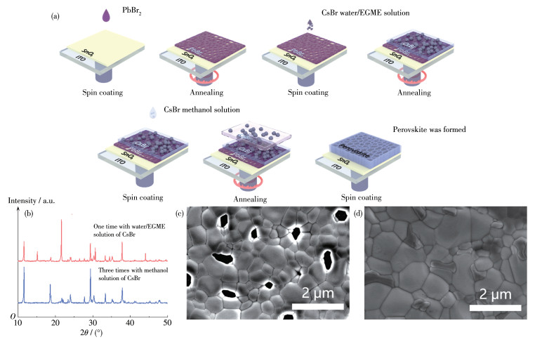
    一般来说,传统制备CsPbBr3薄膜的方法是在PbBr2旋涂、退火完毕后,使用CsBr的甲醇溶液进行旋涂,但由于CsBr在甲醇溶液内的溶解度极低,若想要制备均匀且厚度适中的CsPbBr3薄膜,则需要进行多次旋涂,旋涂遍数往往高达8~9遍,过程十分烦琐。而本课题选用水/EGME双溶剂来溶解CsBr,可使CsBr在该体系中的溶解度远高于在甲醇中的溶解度,达到200 mg·mL-1,成功降低了后续CsBr的甲醇溶液的旋涂遍数,是一种可以高效制备均匀CsPbBr3薄膜的方法。图 1a为制备CsPbBr3薄膜的流程图。

    图 1

    图 1.  (a) 双溶剂法制备CsPbBr3薄膜的流程图; (b) 旋涂3遍15 mg·mL-1 CsBr的甲醇溶液及旋涂1遍200 mg·mL-1 CsBr的水/EGME溶液制备的CsPbBr3薄膜的XRD图; (c) 旋涂3遍15 mg·mL-1 CsBr的甲醇溶液制备的CsPbBr3薄膜的表面SEM图; (d) 旋涂1遍200 mg·mL-1 CsBr的水/EGME溶液制备的CsPbBr3薄膜的表面SEM图
    Figure 1.  (a) Schematic illustration of fabrication process of perovskite film by bi-solvent method; (b) XRD patterns of CsPbBr3 films prepared by spinning coating three times with the methanol solution of 15 mg·mL-1 CsBr and one time with the water/EGME solution of 200 mg·mL-1 CsBr, respectively; (c) SEM image of CsPbBr3 film prepared by spinning coating three times with the methanol solution of 15 mg·mL-1 CsBr; (d) SEM image of CsPbBr3 film prepared by spinning coating one time with the water/EGME solution of 200 mg·mL-1 CsBr

    采用XRD测试观察CsPbBr3相的生成情况,从而探究水/EGME双溶剂对于CsBr溶解度的影响。从图 1b中看出,旋涂一遍200 mg·mL-1 CsBr的水/ EGME溶液后的样品在15.7°、21.5°、30.6°和37.7°处出现明显的衍射峰,而这些衍射峰分别对应于CsPbBr3相(PDF No.54-0752)的(100)、(110)、(200)和(211)面[22]。而旋涂3遍15 mg·mL-1 CsBr的甲醇溶液制备的样品中仍然没有观测到属于CsPbBr3相的特征峰,由此可以证明水/EGME双溶剂能够加大CsBr的溶解度。并且与甲醇溶剂相比,使用水/EGME双溶剂可以在尽可能减少旋涂遍数的同时制备出结晶度较高的CsPbBr3薄膜。经查阅文献可知,在PbBr2与CsBr反应时除了会生成CsPbBr3相外,还会生成四方CsPb2Br5杂相和八面体Cs4PbBr6结构相[19, 23]。其中CsPb2Br5相的生成是由于结构中含有过量的PbBr2,其(110)、(104)和(210)面分别位于11.7°、29.3°和33.5°[24],而Cs4PbBr6相的生成是由于结构中含有过量的CsBr,其特征峰大概位于12.9°、22.5°和27.6°。反应机理如下[25-26]

    $ {\mathrm{CsBr}}+2 {\mathrm{PbBr}}_2 \rightarrow {\mathrm{CsPb}}_2 {\mathrm{Br}}_5 $

    (1)

    $ {\mathrm{CsPbBr}}_3+{\mathrm{PbBr}}_2 \rightarrow {\mathrm{CsPb}}_2 {\mathrm{Br}}_5 $

    (2)

    $ 4 {\mathrm{CsBr}}+{\mathrm{PbBr}}_2 \rightarrow {\mathrm{Cs}}_4 {\mathrm{PbBr}}_6 $

    (3)

    $ 3 {\mathrm{CsBr}}+{\mathrm{CsPbBr}}_3 \rightarrow {\mathrm{Cs}}_4 {\mathrm{PbBr}}_6 $

    (4)

    为了探究旋涂水/EGME双溶剂溶解的CsBr溶液对于薄膜表面形态的影响,进行了SEM测试。从图 1c可以看出,旋涂3遍15 mg·mL-1 CsBr的甲醇溶液制备的钙钛矿薄膜在ITO表面的覆盖性较差,其表面有大量孔洞出现,且孔洞周围的晶粒有明显凸起,结合上述XRD图分析,此时形成的薄膜以CsPb2Br5相为主,钙钛矿相纯度低。而在图 1d中并未观察到孔洞,证明使用双溶剂制备的薄膜能够更加均匀地覆盖于基底表面,但薄膜均匀性仍然较差,有许多杂相分布在晶粒间,结合XRD的测试结果可以推测是因为此时薄膜中仍然存在大量CsPb2Br5相,使薄膜相纯度不足。

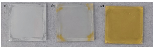
    为了从宏观上观察旋涂水/EGME双溶剂溶解的CsBr溶液对成膜的影响,拍摄了旋涂不同种类及遍数的CsBr溶液的薄膜的宏观图片。从图 2a中可以直观地看出退火后的PbBr2薄膜呈白色雾状。而从图 2b中可以看出在旋涂3遍15 mg·mL-1 CsBr的甲醇溶液后,薄膜边缘处呈黄色,中间大部分面积仍为白色,但透明度有所提高,说明仅有少部分的PbBr2被CsBr反应,印证了上述XRD测试中几乎没有CsPbBr3钙钛矿晶体形成的结果。从图 2c中可以明显地看出,虽然仅仅旋涂了3遍CsBr溶液,但将第1次旋涂所用的溶液换为200 mg·mL-1CsBr的水/EGME溶液后,形成了均匀的黄色薄膜,说明有大量的PbBr2与CsBr反应生成了均匀的CsPbBr3薄膜,这也与上述的XRD和SEM数据相符合。综上所述,水/EGME双溶剂可以有效溶解CsBr,从而大大减少旋涂CsBr的次数,以便用更高效的方法制备均匀且致密的钙钛矿薄膜。

    图 2

    图 2.  薄膜的光学照片: (a) 未旋涂CsBr的PbBr2薄膜; (b) 旋涂3遍15 mg·mL-1 CsBr的甲醇溶液制备的薄膜; (c) 旋涂1遍200 mg·mL-1 CsBr的水/EGME溶液、2遍15 mg·mL-1 CsBr的甲醇溶液制备的薄膜
    Figure 2.  Digital photographs of films: (a) PbBr2 film without CsBr; (b) film prepared by spin coating three times with the methanol solution of 15 mg·mL-1 CsBr; (c) film prepared by spin coating one time with the water/EGME solution of 200 mg·mL-1 CsBr and two times with the methanol solution of 15 mg·mL-1 CsBr

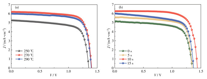
    为了更好优化制备工艺,我们首先探究了旋涂200 mg·mL-1 CsBr的水/EGME溶液时的退火温度和加载时间对器件光电性能的影响。实验以10 s旋涂参数为定量,选取了250、270、290 ℃三个温度来探究最佳退火温度[27]图 3a为在不同退火温度下旋涂1遍200 mg·mL-1 CsBr的水/EGME溶液的基础上旋涂2遍15 mg·mL-1 CsBr的甲醇溶液所制备器件的J-V曲线和具体参数。通过图中曲线以及表 1中的数据,可以很明显地看到当退火温度从250 ℃升到270 ℃时,器件的光伏参数都有很大的提升,并且达到最大值。其VOCJSC、FF、PCE分别为1.40 V、6.22 mA·cm-2、75.42%、6.57%。当退火温度继续上升至290 ℃时,器件的VOCJSC、FF和PCE相较于270 ℃都有较大幅度的下降。因此,通过对比不同退火温度下器件的光伏参数,发现270 ℃为最佳退火温度。确定最佳退火温度后,以退火温度为270 ℃为定量,我们对CsBr溶液在基底上的加载时间进行了优化。结合图 3b表 2的光伏性能参数来看,在旋涂1遍200 mg·mL-1 CsBr的水/EGME溶液的基础上旋涂2遍15 mg·mL-1 CsBr的甲醇溶液,所制备的器件的VOCJSC、FF和PCE均有先增大再减小的趋势,可以看出合适的加载时间在一定程度上能够提高电池的光电性能。而通过以上数据可比较出,当加载时间为10 s时,器件的性能最好,其VOC最大可达到1.44 V,PCE最大可达到6.72%。因此,在后续的实验中,我们将旋涂200 mg·mL-1 CsBr的水/EGME溶液时的加载时间设置为10 s。

    图 3

    图 3.  旋涂1遍200 mg·mL-1 CsBr的水/EGME溶液、2遍CsBr的甲醇溶液所制备的CsPbBr3 PSCs基于(a) 不同退火温度和(b) 不同加载时间的J-V曲线
    Figure 3.  J-V curves of the CsPbBr3 PSCs prepared by spin coating one time with the water/EGME solution of 200 mg·mL-1 CsBr and two times with the methanol solution of 15 mg·mL-1 CsBr based on (a) different annealing temperatures and (b) different loading times

    表 1

    表 1  不同退火温度下PSCs的光伏参数
    Table 1.  Photovoltaic parameters of PSCs with different annealing temperatures
    下载: 导出CSV
    Annealing temperature / ℃ VOC / V JSC / (mA·cm-2) FF / % PCE / %
    250 1.35 5.27 71.41 5.08
    270 1.40 6.22 75.42 6.57
    290 1.39 6.00 74.95 6.25

    表 2

    表 2  不同加载时间下PSCs的光伏参数
    Table 2.  Photovoltaic parameters of PSCs with different loading times
    下载: 导出CSV
    Loading time / s VOC / V JSC / (mA·cm-2) FF / % PCE / %
    0 1.35 5.14 70.62 4.90
    5 1.35 5.61 74.50 5.64
    10 1.44 6.26 74.57 6.72
    15 1.37 6.01 70.70 5.82

    基于以上表征可以看出,在旋涂有PbBr2的基础上,仅旋涂1遍CsBr的水/EGME溶液远远不够,其表面仍有较多CsPb2Br5相存在。因此在后续的研究中,我们选择在CsBr的水/EGME溶液基础上旋涂低浓度的CsBr的甲醇溶液,后者可以作为表面修饰剂,以此来提高CsPbBr3的相纯度,进一步优化器件的制备工艺。

    为探究钙钛矿薄膜表面形貌,对上述钙钛矿薄膜进行了SEM表征,SEM测试结果如图 4a~4d所示。使用Nano Measurer软件对钙钛矿薄膜晶粒尺寸进行统计,结果如图 4e~4h所示。从图 4a可以看出,外加旋涂1次15 mg·mL-1 CsBr的甲醇溶液制备的薄膜已经没有孔洞出现,但仍有大量不规则的晶粒出现在其薄膜表面,此时晶粒较小,分布不均,其钙钛矿晶粒的平均尺寸为0.64 μm,而载流子在晶界处容易发生非辐射复合,不利于载流子传输。从图 4b可以看出,旋涂2次15 mg·mL-1 CsBr的甲醇溶液制备的薄膜晶粒粒径分布更加均匀,平均粒径也有所增大,其平均尺寸为0.87 μm,晶粒间的缺陷有所减少,更有利于减少载流子的复合,有效增加载流子的传输速率,从而提高器件PCE。而从图 4c可以看出,外加3次15 mg·mL-1 CsBr的甲醇溶液制备的薄膜表面,钙钛矿的晶粒虽大但尺寸分布不均,且晶粒间的排列致密度低,形成的薄膜形貌较差。较差的薄膜质量容易导致载流子在传输的过程中发生复合,最终使得电池器件的光电性能下降[28]。从图 4d可以看出,外加旋涂4次15 mg·mL-1 CsBr的甲醇溶液制备的薄膜中除了CsPbBr3相的晶粒外还有其他晶粒生成,初步推测其为Cs4PbBr6相,此时CsBr可能已经过量。通过上述分析,得出结论:在旋涂1遍200 mg·mL-1 CsBr的水/EGME溶液的基础上旋涂2次15 mg·mL-1 CsBr的甲醇溶液制备的钙钛矿薄膜CsPbBr3相晶粒生长最好,薄膜质量最高。此外,通过统计标尺为5 μm的表面SEM图的粒径频率直方图也可以看出,后续旋涂2遍甲醇溶液的钙钛矿薄膜晶粒的分布更集中,平均值更高,远远超过其他遍数下所制备的薄膜粒径平均值。综上,在旋涂1遍200 mg·mL-1 CsBr的水/EGME溶液的基础上旋涂2次15 mg·mL-1 CsBr的甲醇溶液时制备的钙钛矿薄膜具有最优形貌,预期将有利于制备具有更高性能的器件。

    图 4

    图 4.  在旋涂1遍200 mg·mL-1 CsBr的水/EGME溶液的基础上旋涂(a) 1遍、(b) 2遍、(c) 3遍、(d) 4遍15 mg·mL-1 CsBr的甲醇溶液所制备的钙钛矿薄膜的SEM图及(e~h) 相对应的粒径频率直方图
    Figure 4.  SEM images of perovskite films prepared by spinning coating (a) one time, (b) two times, (c) three times, (d) four times with the methanol solution of 15 mg·mL-1 CsBr based on spinning coating one time with the water/EGME solution of 200 mg·mL-1 CsBr and (e-h) corresponding grain size distribution histograms

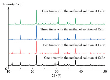
    图 5中可以看出在旋涂1遍200 mg·mL-1 CsBr的水/EGME溶液的基础上随着旋涂15 mg·mL-1 CsBr的甲醇溶液的次数增加,其11.7°和29.3°处CsPb2Br5的特征峰(PDF No.25-0211)不断减弱。在旋涂1遍200 mg·mL-1 CsBr的水/EGME溶液的基础上旋涂4次15 mg·mL-1 CsBr的甲醇溶液时,其CsPb2Br5的特征峰已完全消失,而12.9°和22.5°处的Cs4PbBr6特征峰(PDF No.54-0750)开始出现。通过对比数据,可以明显看出,在旋涂1遍200 mg·mL-1 CsBr的水/EGME溶液的基础上旋涂2遍15 mg·mL-1 CsBr的甲醇溶液时15.7°、21.5°和30.6°处CsPbBr3的特征峰强度显著增加,说明钙钛矿晶粒的结晶度得到改善。虽然图中显示在旋涂1遍双溶剂溶液的基础上旋涂3遍甲醇溶液制备的CsPbBr3薄膜的特征峰强度最高,但其CsPb2Br5相过少。有研究表明CsPbBr3晶粒界面间若有适当的CsPb2Br5相可以实现自钝化[29],有效地消除界面缺陷,降低电子传输势垒,提升器件的PCE。因此可以证明,在旋涂1遍200 mg·mL-1 CsBr的水/EGME溶液的基础上旋涂2遍15 mg·mL-1 CsBr的甲醇溶液,所制备的钙钛矿薄膜性能更好,这与前面SEM图分析结果相一致。

    图 5

    图 5.  在旋涂1遍200 mg·mL-1 CsBr的水/EGME溶液的基础上旋涂不同次数15 mg·mL-1 CsBr的甲醇溶液所制备的CsPbBr3薄膜的XRD图
    Figure 5.  XRD patterns of CsPbBr3 films prepared by spinning coating different times with the methanol solution of 15 mg·mL-1 CsBr based on spinning coating one time with the water/EGME solution of 200 mg·mL-1 CsBr

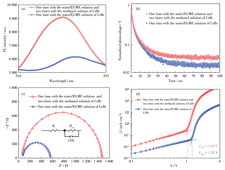
    由于仅旋涂3遍15 mg·mL-1 CsBr的甲醇溶液制备出的空白组器件没有CsPbBr3相的生成,无法对该器件进行PL、TRPL和之后的EIS测试。因此选取了实验最优组和空白组进行PL、TRPL和EIS对比。为探究旋涂CsBr的水/EGME溶液对于形成的钙钛矿薄膜中载流子复合的影响,进行了PL测试。图 6a为PL谱图,从图中可以看出,在旋涂1遍200 mg·mL-1 CsBr的水/EGME溶液基础上旋涂2遍CsBr的甲醇溶液之后,荧光强度大幅提升,表明钙钛矿薄膜中的非辐射复合减少,其原因主要归功于旋涂完2次CsBr的甲醇溶液后,薄膜中CsPbBr3相纯度的提高[30]。对比图中2条曲线可明显看出,在旋涂1遍200 mg·mL-1 CsBr的水/EGME溶液基础上旋涂2遍甲醇溶液制备的薄膜,相较于仅旋涂1遍200 mg·mL-1 CsBr的水/EGME溶液制备的薄膜,曲线发生明显蓝移,这也证明旋涂2遍CsBr的甲醇溶液能有效减少钙钛矿薄膜中的缺陷,使载流子复合中的辐射复合增多,非辐射复合减少,能量更多以光子的形式放出。图 6b为TRPL谱图,相关参数信息列于表 3中。其中,τ1表示非辐射复合有关的快衰减组分寿命,τ2为与辐射复合有关的慢衰减组分寿命,A1A2代表衰减振幅,对于其平均衰减寿命(τave),则用公式τave=A1τ1+A2τ2。如图所示,与仅旋涂1遍200 mg·mL-1 CsBr的水/EGME溶液对比,在此基础上再旋涂2次甲醇溶液之后的钙钛矿薄膜的非辐射复合有关的快衰减组分τ1τ2都有所增加,说明钙钛矿薄膜里的载流子复合过程得到了抑制,提高了载流子的寿命。

    图 6

    图 6.  旋涂1遍200 mg·mL-1 CsBr的水/EGME溶液制备的CsPbBr3薄膜以及在此基础上旋涂2遍CsBr的甲醇溶液制备CsPbBr3薄膜的(a) PL、(b) TRPL、(c) EIS(插图: 等效电路图)和(d) SCLC谱图
    Figure 6.  (a) PL, (b) TRPL, (c) EIS (Inset: equivalent circuit), and (d) SCLC spectra of the CsPbBr3 film prepared by spinning coating one time with the water/EGME solution of 200 mg·mL-1 CsBr and the CsPbBr3 film prepared by spinning coating one time with the water/EGME solution of 200 mg·mL-1 CsBr and two times with the methanol solution of 15 mg·mL-1 CsBr

    表 3

    表 3  图 6b中TRPL对应的相关参数
    Table 3.  Related parameters corresponding to TRPL in Fig. 6b
    下载: 导出CSV
    Process τave / ns A1 / % τ1 / ns A2 / % τ2 / ns
    One time with the water/EGME solution of CsBr 7.49 77.72 9.35 22.28 1.00
    One time with the water/EGME solution and two times with the methanol solution of CsBr 8.27 77.71 10.22 22.29 1.45

    图 6c是在暗态条件下仅旋涂1遍200 mg·mL-1 CsBr的水/EGME溶液制备的器件,及在此基础上旋涂2次15 mg·mL-1 CsBr的甲醇溶液制备的器件的EIS及其等效电路图,暗态EIS通常只显示一个半圆,图中的半圆的半径与电荷的复合电阻(Rrec)有关,其可用于表征器件中的载流子复合过程,该值越大说明界面载流子复合越困难[31]。可以看出,在旋涂1遍200 mg·mL-1 CsBr的水/EGME溶液基础上旋涂2遍甲醇溶液制备的器件,与仅旋涂1遍200 mg·mL-1 CsBr的水/EGME溶液制备的器件对比,Rrec明显增大,表明适当地增加CsBr的甲醇溶液旋涂遍数,可以使电子和空穴的复合阻力增大,有利于载流子的有效提取和传输[32],有利于器件性能的提升。图 6d为利用SCLC方法来测定器件的暗态J-V曲线,并通过公式ntrap=2εε0VTFL/(qL2)[33]来估算器件电子陷阱态密度(ntrap),其中ε为CsPbBr3的相对介电常数,ε0为真空介电常数,q为元电荷,VTFL为极限陷阱填充,L为CsPbBr3薄膜厚度[34]。经过计算可以得出在旋涂1遍200 mg·mL-1 CsBr的水/EGME溶液基础上旋涂1遍15 mg·mL-1 CsBr的甲醇溶液的器件有着更低的ntrap,数值为8.70×1015 cm-3,而只旋涂1遍200 mg·mL-1 CsBr的水/EGME溶液的器件ntrap为1.23×1016 cm-3,证明后续旋涂2遍15 mg·mL-1 CsBr的甲醇溶液有助于减少钙钛矿薄膜的缺陷,从而进一步减少钙钛矿薄膜中的非辐射复合程度。

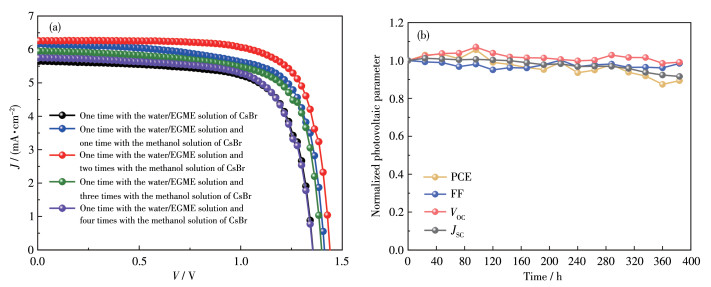
    图 7a为在200 mg·mL-1 CsBr的水/EGME溶液的基础上旋涂不同遍数甲醇溶液制备的器件的J-V曲线,其具体的性能参数见表 4。从这些数据中可以看出在一定范围内,随着旋涂遍数的增加,JSCVOC、FF、PCE均有明显提升。在200 mg·mL-1 CsBr的水/EGME溶液的基础上旋涂2次15 mg·mL-1甲醇溶液时,各性能参数达到最大值,其中VOC达到1.44 V,JSC达到6.26 mA·cm-2,FF达到74.57%,PCE达到6.72%。而后随着遍数的增加,可明显看出电池的光电性能数值开始下降。通过图 7b中器件的光伏性能参数归一化数据可以看出,在旋涂1遍200 mg·mL-1 CsBr的水/EGME溶液的基础上旋涂2遍15 mg·mL-1甲醇溶液,所制备的器件稳定性十分优越。在湿度为20%且无封装的情况下放置17 d,其VOC和FF仍能保持原有的数值,JSC保有其原来性能的90%以上,PCE则为原有的88%以上,都证明了该器件具有非常好的稳定性。

    图 7

    图 7.  在旋涂1遍200 mg·mL-1 CsBr的水/EGME溶液的基础上旋涂不同次数CsBr的甲醇溶液制备的PSCs的J-V曲线; (b) 旋涂1遍200 mg·mL-1 CsBr的水/EGME溶液和旋涂2遍CsBr的甲醇溶液制备的PSCs的归一化VOCJSC、FF、PCE的稳定性
    Figure 7.  (a) J-V curves of PSCs prepared by spinning coating different times with the methanol solution of 15 mg·mL-1 CsBr based on spinning coating one time with the water/EGME solution of 200 mg·mL-1 CsBr; (b) VOC, JSC, FF, and PCE stability of PSCs prepared by spinning coating one time with the water/EGME solution of 200 mg·mL-1 CsBr and two times with the methanol solution of 15 mg·mL-1 CsBr

    表 4

    表 4  不同旋涂遍数制备的PSCs的光伏参数
    Table 4.  Photovoltaic parameters of PSCs prepared with different spin coating times
    下载: 导出CSV
    Process VOC / V JSC / (mA·cm-2) FF / % PCE / %
    One time with the water/EGME solution of CsBr 1.36 5.65 71.30 5.48
    One time with the water/EGME solution and one time with the the methanol solution of CsBr 1.41 6.17 71.33 6.21
    One time with the water/EGME solution and two times with the methanol solution of CsBr 1.44 6.26 74.57 6.72
    One time with the water/EGME solution and three times with the methanol solution of CsBr 1.40 5.95 71.66 5.97
    One time with the water/EGME solution and four times with the methanol solution of CsBr 1.36 5.75 70.47 5.51
    Three times with the methanol solution of CsBr 0.03

    对ITO/SnO2/CsPbBr3/Carbon结构的全无机钙钛矿太阳能电池的制备工艺进行优化,通过使用对CsBr溶解度较大的水醚混合溶剂,来降低器件的旋涂遍数。当在退火温度为270 ℃,加载时间为10 s的条件下旋涂200 mg·mL-1 CsBr的水/EGME溶液,可以使器件的性能达到最佳。之后又在此基础上旋涂不同遍数的CsBr的甲醇溶液,当旋涂2遍CsBr的甲醇溶液时,CsPbBr3钙钛矿的薄膜形貌最好,载流子寿命最长,非辐射性复合最少,基于此制备出的器件具有较好的光学性能,且各项性能参数达到了最大值,其中VOC达到1.44 V,JSC达到6.26 mA·cm-2,FF达到74.57%,PCE达到6.72%。总之,本课题提供了一个更为高效且绿色环保的制备路径,是基于传统全无机CsPbBr3钙钛矿太阳能电池制备工艺的一次探索创新。


    1. [1]

      Kojima A, Teshima K, Shirai Y, Miyasaka T. Organometal halide perovskites as visible-light sensitizers for photovoltaic cells[J]. J. Am. Chem. Soc., 2009, 131(17):  6050-6051. doi: 10.1021/ja809598r

    2. [2]

      NREL. Best research-cell efficiency chart. https://www.nrel.gov/pv/cell-efficiency.html.

    3. [3]

      Akkerman Q A, Manna L. What defines a halide perovskite?[J]. ACS Energy Lett., 2020, 5(2):  604-610. doi: 10.1021/acsenergylett.0c00039

    4. [4]

      Xu L, Wu D, Lv W X, Xiang Y, Liu Y, Tao Y, Yin J, Qian M Y, Li P, Zhang L Q, Chen S F, Mohammed O F, Bakr O M, Duan Z, Chen R F, Huang W. Resonance-mediated dynamic modulation of perovskite crystallization for efficient and stable solar cells[J]. Adv. Mater., 2021, 34(6):  2107111.

    5. [5]

      邹宇, 李昭, 陈衡慧, 刘伊辰, 童安玲, 颜惠英, 何若玮, 花国鑫, 曾伟东, 孙伟海. NaTFSI界面修饰对平面TiO2基钙钛矿太阳能电池的影响[J]. 发光学报, 2021,42,(5): 682-690. doi: 10.37188/CJL.20210045ZOU Y, LI Z, CHEN H H, LIU Y C, TONG A L, YAN H Y, HE R W, HUA G X, ZENG W D, SUN W H. Effect of NaTFSI interface modification on flat TiO2-based perovskite solar cells[J]. Chin. J. Lumin., 2021, 42(5):  682-690. doi: 10.37188/CJL.20210045

    6. [6]

      Shaw B K, Castillo-Blas C, Thorne M F, Ríos Gómez M L, Forrest T, Lopez M D, Chater P A, McHugh L N, Keen D A, Bennett T D. Principles of melting in hybrid organic-inorganic perovskite and polymorphic ABX3 structures[J]. Chem. Sci., 2022, 13(7):  2033-2042. doi: 10.1039/D1SC07080K

    7. [7]

      Li N X, Tao S X, Chen Y H, Niu X X, Onwudinanti C K, Hu C, Qiu Z W, Xu Z Q, Zheng G H, Wang L G, Zhang Y, Li L, Liu H F, Lun Y Z, Hong J W, Wang X Y, Liu Y Q, Xie H P, Gao Y L, Bai Y, Yang S H, Brocks G, Chen Q, Zhou H P. Cation and anion immobilization through chemical bonding enhancement with fluorides for stable halide perovskite solar cells[J]. Nat Energy, 2019, 4(5):  408-415. doi: 10.1038/s41560-019-0382-6

    8. [8]

      Bai S, Da P M, Li C, Wang Z P, Yuan Z C, Fu F, Kawecki M, Liu X J, Sakai N, Wang J T W, Huettner S, Buecheler S, Fahlman M, Gao F, Snaith H J. Planar perovskite solar cells with long-term stability using ionic liquid additives[J]. Nature, 2019, 571(7764):  245-250. doi: 10.1038/s41586-019-1357-2

    9. [9]

      Jeon N J, Noh J H, Yang W S, Kim Y C, Ryu S, Seo J, Seok S I. Compositional engineering of perovskite materials for high-performance solar cells[J]. Nature, 2015, 517(7535):  476-480. doi: 10.1038/nature14133

    10. [10]

      Shao Y C, Wang Q, Dong Q F, Yuan Y B, Huang J S. Vacuum-free laminated top electrode with conductive tapes for scalable manufacturing of efficient perovskite solar cells[J]. Nano Energy, 2015, 16:  47-53. doi: 10.1016/j.nanoen.2015.06.010

    11. [11]

      Kumar N, Rani N J, Kurchania R. Advancement in CsPbBr3 inorganic perovskite solar cells: Fabrication, efficiency and stability[J]. Sol. Energy, 2021, 221:  197-205. doi: 10.1016/j.solener.2021.04.042

    12. [12]

      Li B, Fu L, Li S, Li H, Pan L, Wang L, Chang B H, Yin L W. Pathways toward high-performance inorganic perovskite solar cells: challenges and strategies[J]. J. Mater. Chem. A, 2019, 7(36):  20494-20518. doi: 10.1039/C9TA04114A

    13. [13]

      Zhou Q W, Duan J L, Du J, Guo Q Y, Zhang Q Y, Yang X Y, Duan Y Y, Tang Q W. Tailored lattice "tape" to confine tensile interface for 11.08%-efficiency all-inorganic CsPbBr3 perovskite solar cell with an ultrahigh voltage of 1.702 V[J]. Adv. Sci., 2021, 8(19):  2101418. doi: 10.1002/advs.202101418

    14. [14]

      Kieslich G, Sun S J, Cheetham A K. Solid-state principles applied to organic-inorganic perovskites: New tricks for an old dog[J]. Chem. Sci., 2014, 5(12):  4712-4715. doi: 10.1039/C4SC02211D

    15. [15]

      Gao P, Grätzel M, Nazeeruddin M K. Organohalide lead perovskites for photovoltaic applications[J]. Energy Environ. Sci., 2014, 7(8):  2448-2463. doi: 10.1039/C4EE00942H

    16. [16]

      Kulbak M, Cahen D, Hodes G. How important is the organic part of lead halide perovskite photovoltaic cells? Efficient CsPbBr3 cells[J]. J. Phys. Chem. Lett., 2015, 6(13):  2452-2456. doi: 10.1021/acs.jpclett.5b00968

    17. [17]

      Chen J L, Qiu W, Huang C Y, Wu L, Liu C, Tian Q Q, Peng Z Y, Chen J. A novel solvent for multistep solution-processed planar CsPbBr3 perovskite solar cells using In2S3 as electron transport layer[J]. Energy Technol., 2022, 10(6):  2200054. doi: 10.1002/ente.202200054

    18. [18]

      Cao X B, Zhang G S, Cai Y F, Jiang L, Yang W J, Song W D, He X, Zeng Q G, Jia Y, Wei J Q. A sustainable solvent system for processing CsPbBr3 films for solar cells via an anomalous sequential deposition route[J]. Green Chem., 2021, 23(1):  470-478. doi: 10.1039/D0GC02892D

    19. [19]

      Liu X Y, Tan X H, Liu Z Y, Ye H B, Sun B, Shi T L, Tang Z R, Liao G L. Boosting the efficiency of carbon-based planar CsPbBr3 perovskite solar cells by a modified multistep spin-coating technique and interface engineering[J]. Nano Energy, 2019, 56:  184-195. doi: 10.1016/j.nanoen.2018.11.053

    20. [20]

      Cao X B, Zhang G S, Cai Y F, Jiang L, He X, Zeng Q G, Wei J Q, Jia Y, Xing G C, Huang W. All green solvents for fabrication of CsPbBr3 films for efficient solar cells guided by the hansen solubility theory[J]. Sol. RRL, 2020, 4(4):  2000008. doi: 10.1002/solr.202000008

    21. [21]

      韩丽华, 金建新, 宰学荣, 杨尚林. 纳米SnO2粉体团聚的控制[J]. 材料开发与应用, 2005(6): 30-33. doi: 10.3969/j.issn.1003-1545.2005.06.009HAN L H, JIN J X, ZAI X R, YANG S L. Control of nano-SnO2 powder agglomeration[J]. Development and Application of Materials, 2005, (6):  30-33. doi: 10.3969/j.issn.1003-1545.2005.06.009

    22. [22]

      Zhu J W, He B L, Yao X P, Chen H Y, Duan Y Y, Duan J L, Tang Q W. Phase control of Cs-Pb-Br derivatives to suppress 0D Cs4PbB6 for high-efficiency and stable all-inorganic CsPbBr3 perovskite solar cells[J]. Small, 2022, 18(8):  2106323. doi: 10.1002/smll.202106323

    23. [23]

      Duan J L, Zhao Y Y, He B L, Tang Q W. High-purity inorganic perovskite films for solar cells with 9.72 % efficiency[J]. Angew. Chem. Int. Ed., 2018, 130(14):  3849-3853. doi: 10.1002/ange.201800019

    24. [24]

      Li H, Tong G Q, Chen T T, Zhu H W, Li G P, Chang Y J, Wang L, Jiang Y. Interface engineering using a perovskite derivative phase for efficient and stable CsPbBr3 solar cells[J]. J. Mater. Chem. A, 2018, 6(29):  14255-14261. doi: 10.1039/C8TA03811B

    25. [25]

      Tong G Q, Ono L K, Qi Y B. Recent progress of all-bromide inorganic perovskite solar cells[J]. Energy Technol., 2020, 8(4):  1900961. doi: 10.1002/ente.201900961

    26. [26]

      Saidaminov M I, Almutlaq J, Sarmah S, Dursun I, Zhumekenov A A, Begum R, Pan J, Cho N, Mohammed O F, Bakr O M. Pure Cs4PbBr6: Highly luminescent zero-dimensional perovskite solids[J]. ACS Energy Lett., 2016, 1(4):  840-845. doi: 10.1021/acsenergylett.6b00396

    27. [27]

      Wang S B, Cao F X, Sun W H, Wang C Y, Yan Z G, Wang N, Lan Z, Wu J H. A green bi-solvent system for processing high-quality CsPbBr3 films in efficient all-inorganic perovskite solar cells[J]. Mater. Today Phys., 2022, 22:  100614. doi: 10.1016/j.mtphys.2022.100614

    28. [28]

      Zhang W Y, Liu X J, He B L, Gong Z K, Zhu J W, Ding Y, Chen H Y, Tang Q W. Interface engineering of imidazolium ionic liquids toward efficient and stable CsPbBr3 perovskite solar cells[J]. ACS Appl. Mater. Interfaces, 2020, 12(4):  4540-4548. doi: 10.1021/acsami.9b20831

    29. [29]

      Zhang X L, Xu B, Zhang J B, Gao Y, Zheng Y J, Wang K, Sun X W. All-inorganic perovskite nanocrystals for high-efficiency light emitting diodes: dual-phase CsPbBr3-CsPb2Br5 composites[J]. Adv. Funct. Mater., 2016, 26(25):  4595-4600. doi: 10.1002/adfm.201600958

    30. [30]

      Teng P P, Han X P, Li J W, Xu Y, Kang L, Wang Y R, Yang Y, Yu T. Elegant face-down liquid-space-restricted deposition of CsPbBr3 films for efficient carbon-based all-inorganic planar perovskite solar cells[J]. ACS Appl. Mater. Interfaces, 2018, 10(11):  9541-9546. doi: 10.1021/acsami.8b00358

    31. [31]

      Wang K, Shi Y T, Gao L G, Chi R H, Shi K, Guo B Y, Zhao L, Ma T L. W(Nb)Ox-based efficient flexible perovskite solar cells: from material optimization to working principle[J]. Nano Energy, 2017, 31:  424-431. doi: 10.1016/j.nanoen.2016.11.054

    32. [32]

      Ding Y, He B L, Zhu J W, Zhang W Y, Su G D, Duan J L, Zhao Y Y, Chen H Y, Tang Q W. Advanced modification of perovskite surfaces for defect passivation and efficient charge extraction in air-stable CsPbBr3 perovskite solar cells[J]. ACS Sustain. Chem. Eng., 2019, 7(23):  19286-19294. doi: 10.1021/acssuschemeng.9b05631

    33. [33]

      Liang K B, Wu Y J, Zhen Q S, Zou Y, Zhang X C, Wang C H, Shi P Y, Zhang Y Y, Sun W H, Li Y L, Wu J H. Solvent vapor annealing-assisted mesoporous PbBr2 frameworks for high-performance inorganic CsPbBr3 perovskite solar cells[J]. Surf. Interfaces, 2023, 37:  102707. doi: 10.1016/j.surfin.2023.102707

    34. [34]

      Tong A L, Zhu C W, Yan H Y, Zhang C H, Jin Y N, Wu Y J, Cao F X, Wu J H, Sun W H. Defect control for high-efficiency all-inorganic CsPbBr3 perovskite solar cells via hydrophobic polymer interface passivation[J]. J. Alloy. Compd., 2023, 942:  169084. doi: 10.1016/j.jallcom.2023.169084

  • 图 1  (a) 双溶剂法制备CsPbBr3薄膜的流程图; (b) 旋涂3遍15 mg·mL-1 CsBr的甲醇溶液及旋涂1遍200 mg·mL-1 CsBr的水/EGME溶液制备的CsPbBr3薄膜的XRD图; (c) 旋涂3遍15 mg·mL-1 CsBr的甲醇溶液制备的CsPbBr3薄膜的表面SEM图; (d) 旋涂1遍200 mg·mL-1 CsBr的水/EGME溶液制备的CsPbBr3薄膜的表面SEM图

    Figure 1  (a) Schematic illustration of fabrication process of perovskite film by bi-solvent method; (b) XRD patterns of CsPbBr3 films prepared by spinning coating three times with the methanol solution of 15 mg·mL-1 CsBr and one time with the water/EGME solution of 200 mg·mL-1 CsBr, respectively; (c) SEM image of CsPbBr3 film prepared by spinning coating three times with the methanol solution of 15 mg·mL-1 CsBr; (d) SEM image of CsPbBr3 film prepared by spinning coating one time with the water/EGME solution of 200 mg·mL-1 CsBr

    图 2  薄膜的光学照片: (a) 未旋涂CsBr的PbBr2薄膜; (b) 旋涂3遍15 mg·mL-1 CsBr的甲醇溶液制备的薄膜; (c) 旋涂1遍200 mg·mL-1 CsBr的水/EGME溶液、2遍15 mg·mL-1 CsBr的甲醇溶液制备的薄膜

    Figure 2  Digital photographs of films: (a) PbBr2 film without CsBr; (b) film prepared by spin coating three times with the methanol solution of 15 mg·mL-1 CsBr; (c) film prepared by spin coating one time with the water/EGME solution of 200 mg·mL-1 CsBr and two times with the methanol solution of 15 mg·mL-1 CsBr

    图 3  旋涂1遍200 mg·mL-1 CsBr的水/EGME溶液、2遍CsBr的甲醇溶液所制备的CsPbBr3 PSCs基于(a) 不同退火温度和(b) 不同加载时间的J-V曲线

    Figure 3  J-V curves of the CsPbBr3 PSCs prepared by spin coating one time with the water/EGME solution of 200 mg·mL-1 CsBr and two times with the methanol solution of 15 mg·mL-1 CsBr based on (a) different annealing temperatures and (b) different loading times

    图 4  在旋涂1遍200 mg·mL-1 CsBr的水/EGME溶液的基础上旋涂(a) 1遍、(b) 2遍、(c) 3遍、(d) 4遍15 mg·mL-1 CsBr的甲醇溶液所制备的钙钛矿薄膜的SEM图及(e~h) 相对应的粒径频率直方图

    Figure 4  SEM images of perovskite films prepared by spinning coating (a) one time, (b) two times, (c) three times, (d) four times with the methanol solution of 15 mg·mL-1 CsBr based on spinning coating one time with the water/EGME solution of 200 mg·mL-1 CsBr and (e-h) corresponding grain size distribution histograms

    图 5  在旋涂1遍200 mg·mL-1 CsBr的水/EGME溶液的基础上旋涂不同次数15 mg·mL-1 CsBr的甲醇溶液所制备的CsPbBr3薄膜的XRD图

    Figure 5  XRD patterns of CsPbBr3 films prepared by spinning coating different times with the methanol solution of 15 mg·mL-1 CsBr based on spinning coating one time with the water/EGME solution of 200 mg·mL-1 CsBr

    图 6  旋涂1遍200 mg·mL-1 CsBr的水/EGME溶液制备的CsPbBr3薄膜以及在此基础上旋涂2遍CsBr的甲醇溶液制备CsPbBr3薄膜的(a) PL、(b) TRPL、(c) EIS(插图: 等效电路图)和(d) SCLC谱图

    Figure 6  (a) PL, (b) TRPL, (c) EIS (Inset: equivalent circuit), and (d) SCLC spectra of the CsPbBr3 film prepared by spinning coating one time with the water/EGME solution of 200 mg·mL-1 CsBr and the CsPbBr3 film prepared by spinning coating one time with the water/EGME solution of 200 mg·mL-1 CsBr and two times with the methanol solution of 15 mg·mL-1 CsBr

    图 7  在旋涂1遍200 mg·mL-1 CsBr的水/EGME溶液的基础上旋涂不同次数CsBr的甲醇溶液制备的PSCs的J-V曲线; (b) 旋涂1遍200 mg·mL-1 CsBr的水/EGME溶液和旋涂2遍CsBr的甲醇溶液制备的PSCs的归一化VOCJSC、FF、PCE的稳定性

    Figure 7  (a) J-V curves of PSCs prepared by spinning coating different times with the methanol solution of 15 mg·mL-1 CsBr based on spinning coating one time with the water/EGME solution of 200 mg·mL-1 CsBr; (b) VOC, JSC, FF, and PCE stability of PSCs prepared by spinning coating one time with the water/EGME solution of 200 mg·mL-1 CsBr and two times with the methanol solution of 15 mg·mL-1 CsBr

    表 1  不同退火温度下PSCs的光伏参数

    Table 1.  Photovoltaic parameters of PSCs with different annealing temperatures

    Annealing temperature / ℃ VOC / V JSC / (mA·cm-2) FF / % PCE / %
    250 1.35 5.27 71.41 5.08
    270 1.40 6.22 75.42 6.57
    290 1.39 6.00 74.95 6.25
    下载: 导出CSV

    表 2  不同加载时间下PSCs的光伏参数

    Table 2.  Photovoltaic parameters of PSCs with different loading times

    Loading time / s VOC / V JSC / (mA·cm-2) FF / % PCE / %
    0 1.35 5.14 70.62 4.90
    5 1.35 5.61 74.50 5.64
    10 1.44 6.26 74.57 6.72
    15 1.37 6.01 70.70 5.82
    下载: 导出CSV

    表 3  图 6b中TRPL对应的相关参数

    Table 3.  Related parameters corresponding to TRPL in Fig. 6b

    Process τave / ns A1 / % τ1 / ns A2 / % τ2 / ns
    One time with the water/EGME solution of CsBr 7.49 77.72 9.35 22.28 1.00
    One time with the water/EGME solution and two times with the methanol solution of CsBr 8.27 77.71 10.22 22.29 1.45
    下载: 导出CSV

    表 4  不同旋涂遍数制备的PSCs的光伏参数

    Table 4.  Photovoltaic parameters of PSCs prepared with different spin coating times

    Process VOC / V JSC / (mA·cm-2) FF / % PCE / %
    One time with the water/EGME solution of CsBr 1.36 5.65 71.30 5.48
    One time with the water/EGME solution and one time with the the methanol solution of CsBr 1.41 6.17 71.33 6.21
    One time with the water/EGME solution and two times with the methanol solution of CsBr 1.44 6.26 74.57 6.72
    One time with the water/EGME solution and three times with the methanol solution of CsBr 1.40 5.95 71.66 5.97
    One time with the water/EGME solution and four times with the methanol solution of CsBr 1.36 5.75 70.47 5.51
    Three times with the methanol solution of CsBr 0.03
    下载: 导出CSV
  • 加载中
计量
  • PDF下载量:  21
  • 文章访问数:  5829
  • HTML全文浏览量:  799
文章相关
  • 发布日期:  2023-06-10
  • 收稿日期:  2022-12-23
  • 修回日期:  2023-05-04
通讯作者: 陈斌, bchen63@163.com
  • 1. 

    沈阳化工大学材料科学与工程学院 沈阳 110142

  1. 本站搜索
  2. 百度学术搜索
  3. 万方数据库搜索
  4. CNKI搜索

/

返回文章