Figure 1.
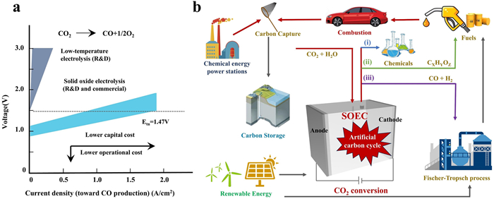
(a) Comparison of various CO2 electrolysis technologies Reprinted with permission [12]. Copyright 2020, American Association for the Advancement of Science. (b) The artificial carbon cycle with the aid of SOEC.
Electrosynthesizing high-value fuels from CO2 in solid oxide electrolysis cells: Fundamentals, advances, and perspectives
Ming Yang , Lin-Bo Liu , Shuo Liu , Yan Li , Biao Ouyang , Xian-Zhu Fu , Jing-Li Luo , Yifei Sun , Subiao Liu

With the sharply growing consumption of fossil fuels, the global CO2 emissions have soared year by year, leading to increasingly serious problems such as air pollution and climate warming [1–3]. According to the International Energy Agency, the global CO2 emissions in 2023 reached 37.4 Gt, which is nearly 50 times higher than the levels recorded during the inception of the industrial revolution in the 1750s [4]. Therefore, it is imperative to turn our energy systems toward low-carbon energy sources. In this regard, renewable clean energies (e.g., wind, solar, tidal, and geothermal energy) could satisfy the global power demand many times over, but the intermittent and locality nature greatly impede their large-scale commercial utilization. However, when powered by renewable and clean energies, thermochemical, photochemical, and electrochemical CO2 conversion to produce high-value fuels and chemicals are promising technologies to address these issues, so as to achieve the dual goals of carbon emission peak and carbon neutrality [5–10]. Among them, electrochemical CO2 conversion has particular advantages since that (1) by adjusting electrochemical reaction conditions such as voltage, current density, and temperature, the reaction rate and selectivity can be precisely controlled, and (2) electrochemical devices typically feature the modular design, facilitating the scalability and distributed deployment suitable for various application scenarios.
Currently, there are two common approaches to realize electrochemical CO2 conversion, i.e., room-temperature (< 373 K) CO2 reduction reaction (RT-CO2RR) in static or flow cells, and high-temperature (> 873 K) CO2 reduction reaction (HT-CO2RR) in solid oxide electrolysis cells (SOECs). More specifically, the RT-CO2RR system is simple and easy to manufacture, where the CO2 molecules dissolved in liquid electrolyte (e.g., NaHCO3 and KHCO3) are served as reactants, and various fuels/chemicals (e.g., CO, HCOOH, CH3OH, CH4, C2H4) could be produced due to the multi-proton-coupled electron-transfer process in aqueous solution [11]. Nevertheless, RT-CO2RR generally suffers from many problems, e.g., low Faradaic efficiency toward target product due to the complicated mechanism, the existence of competitive hydrogen evolution reaction (HER), low current density caused by the low solubility, slow mass transfer of CO2 in aqueous solution, and high cost for product separation. Although the emerging gas-diffusion electrodes employed in flow cells could address these problems to some content, the complex fabrication and insufficient conversion efficiency still hinder them for large-scale application. Nevertheless, HT-CO2RR in SOECs completely bypasses these issues, since the high temperature could accelerate the reaction kinetics and reduce the internal resistance, where the gaseous CO2 rapidly diffuses to the electrode, leading to a high current density and energy efficiency as compared to the RT-CO2RR under the similar conditions, ultimately lowering both the capital and operational costs (Fig. 1a) [12]. Simultaneously, the solid electrolyte and single gas product of SOECs could reduce the influence of external factors on the electrode, guaranteeing a long-term stability. Additionally, SOECs hold great potential to produce various high-value fuels (e.g., H2, C2H4) from various feedstocks (e.g., H2O, CH4 and C2H6), especially when coupled with renewable energy, which is expected to drive the artificial carbon cycle for future energy systems (Fig. 1b) [13,14].
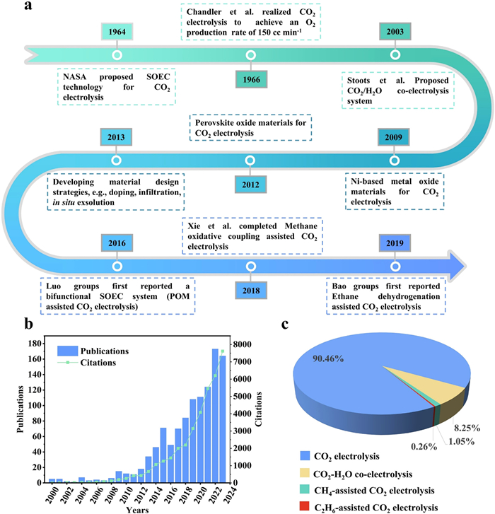
The main development history of SOECs for converting CO2 can be actually traced back to the 1960s when the concept was initially proposed, as shown in Fig. 2a. Following this, the National Aeronautics and Space Administration utilized SOEC to electrolyze CO2 from the Martian atmosphere for O2 generation [15]. Shortly after, Chandler et al. carried out the experiment of utilizing SOECs to reduce CO2 in the laboratory, and achieved an O2 production rate of 150 mL/min [16]. Subsequently, due to the competitive disadvantage caused by the low price of fossil fuels, the development of SOEC was slowed down. However, by the end of the 20th century, it again gained increasing attention as a green energy technology. Researchers were continuously exploring advanced materials suitable for CO2RR. With the rapid advances in theory and characterization techniques, and the fast development of various material design strategies [17–20], the research on its related applications was expanding (Figs. 2b and c). In 2003, the National Laboratory of Denmark first proposed to utilize CO2/H2O co-electrolysis for syngas (i.e., CO + H2) production, which could be used as the fuel gas to effectively generate electrical power in solid oxide fuel cell (SOFCs), i.e., inverse devices of SOECs [21], and as the initial gas to synthesize a variety of hydrocarbons via the Fischer–Tropsch (F–T) reaction, offering a more efficient route for power storage [22,23]. Later in 2016, Sun et al. reported a dual-functional SOEC system that simultaneously conducted CO2RR at the cathode side and the partial oxidation of methane (POM) at the anode side to synthesize syngas in a one-step process [24–26]. This work provided a completely new direction for HT-CO2RR. Inspired by this, Xu et al. conducted preliminary modeling studies on fuel-assisted SOEC for H2O/CO2 co-electrolysis, and the results indicated that CH4 assistance effectively reduced the equilibrium potential of SOEC, which significantly lowered the electrical energy consumption during H2O/CO2 co-electrolysis in SOECs [27]. Subsequently, researchers also investigated the use of CH4-assisted H2O/CO2 co-electrolysis. In addition, there also have been relevant reports on CH4 or C2H6 dehydrogenation to produce C2H4 at the SOEC anode side, and their assisted CO2RR [28–31]. In fact, all these studies have provided new pathways for effectively reducing CO2.
Despite remarkable progress having been achieved, CO2RR in SOEC is not sufficiently mature to meet the commercial demands due to the issues such as the insufficient catalytic activity, the poor long-term stability, and the high cost [32–35]. Thus, developing electrocatalysts with high activity, long-term stability, and low cost is crucial for the ultimately practical application of SOEC technology to electrosynthesize high-value fuels from CO2 [36]. Currently, the perovskite oxide family, typically having the chemical formula ABO3, shows great potential to serve as active and stable electrocatalysts in SOECs due to their tunable crystal and electronic structures, high ionic and electronic conductivities, and rapid oxygen exchange kinetics [37]. Other derivatives, such as double perovskite oxides (A2B2O6) and Ruddlesden–Popper perovskite oxides (RP, An+1BnO3n+1), have also been extensively studied for SOEC application because of their high electrolytic performance and structural stability in reducing atmospheres [35,38–42]. However, the selection criteria (e.g., crystal structure, composition, and component) of perovskite oxides for different electrolysis reactions are application-oriented, and differ from each other. This review is thus mainly focused on the SOEC fundamentals (e.g., working principle of SOEC, thermodynamics, kinetics, and evaluation parameters), specific electrolysis reactions (e.g., CO2 electrolysis, H2O-CO2 co-electrolysis, and fuel-assisted CO2 conversion) and their associated preference for material selection to electrosynthesize high-value fuels in SOECs in pursuit of advancing the research and development of electrochemical CO2 conversion, and accelerating their large-scale applications.
Understanding the working principles of electrochemical CO2 conversion within SOEC is crucial to guide the material design. A typical SOEC generally consists of an anode, a cathode, and a dense electrolyte. Depending on the electrolyte type, it can be categorized as oxygen ion-conducting SOEC (O-SOEC) and proton-conducting SOEC (H-SOEC) (Figs. 3a and b). Each electrolyte type suits different specific reactions at cathode and/or anode. For the oxygen ion-conducting electrolyte, CO2 molecules gain electrons at cathode, and generate CO and O2−, then the formed O2− ions traverse the electrolyte to the anode, where electrons are released and O2 molecules are formed. For the proton-conducting electrolyte, the CO2 electrolysis is facilitated by the aid of H2O splitting, where CO2 is introduced to the cathode, while H2O is supplied to the anode, and loses electrons to produce O2 molecules and protons. The formed protons then pass through the electrolyte to the cathode, where they receive electrons and react with CO2 molecules, yielding CO or other valuable chemicals.

CO2 is a linear molecule, among which C and O atoms form a C═O double bond through an electron sharing. This double bond possesses a bond energy of 803 kJ/mol [43], significantly surpassing the bond energy of O—H (463 kJ/mol) in H2O molecule [44]. However, the C═O bond is highly stable, making CO2 conversion thermodynamically challenging. At high temperatures, the associated reactions for electrochemical CO2 conversion are endothermic processes, and the thermodynamic parameters, such as enthalpy change (ΔH), Gibbs free energy change (ΔG), and entropy change (ΔS), are temperature-dependent, which can be expressed by Eq. 1. The energy demands for various electrochemical CO2 conversion processes are depicted in Figs. 4a and b, where ΔH, ΔG, and TΔS represent the required total energy requirement, electrical energy requirement, and thermal energy, respectively. With increasing the temperature, the total energy demand remains nearly constant, whereas the required heat for CO2 decomposition tends to increase, and the electrical energy tends to decrease, due to the increase in entropy (ΔS > 0). As compared to low- and intermediate-temperature electrolysis, high-temperature electrolysis can utilize both electricity and heat to achieve high reaction rates with a low internal resistance in the cell under the same voltage. This means that high-temperature electrolysis can take effective use of industrial waste heat and electricity generated from renewable energy sources, thereby enhancing environmental and economic benefits.

In a practical electrolysis operation, the heat required for electrolysis mainly comes from two sources, i.e., the external heating system and the Joule heat generated by the current passing through the electrolytic cell. When all the heat required for electrolysis is provided by the external heating system, the electrolysis only supplies the reversible potential, denoted as
|
|
(1) |
|
|
(2) |
|
|
(3) |
However, it is worth noting that in actual electrolysis process, the partial pressures of reactants and products also influence the reversible voltage. Therefore, the reversible voltages under different pressures and temperatures are normally determined by the Nernst equation, as shown in Eq. 3, where R represents the gas constant, while pCO,
The thermodynamic analysis is conducted based on the assumption of ideal conditions, where the cell operates without any short-circuits or internal resistance. Under the ideal conditions, the reversible potential (Erev) is equivalent to the theoretical open circuit voltage (Vocv) However, in practical operations, all the CO2 conversion reactions involve several complex processes, including electrode activation, charge transfer, and mass transfer, thus a certain potential is required, which is mainly associated with the activation overpotential (ɳact), ohmic overpotential (ɳohm), and concentration overpotential (ɳcon), respectively. Additionally, a minor amount of potential leakage, denoted as (ɳleak), might be present throughout the entire SOEC electrolysis system. As a result, the actual measured open circuit voltage (VExp) in the SOEC often falls below the theoretical open circuit voltage (Vocv).
|
|
(4) |
Based on the thermodynamics and kinetics, converting CO2 at high-temperature conditions in SOEC possesses many advantages, such as a reduced energy demand, a decreased reaction overpotential, and an enhanced oxygen ion diffusion, as compared to other electrolyzes. However, the practical operation poses challenges due to the high operating temperature, which not only limits the material selection suitable for SOEC assembling, but also escalates the manufacturing and operational costs. Moreover, the elevated high temperature accelerates the material degradation, resulting in a high maintenance expense [45,46]. In response, developing high-performance electrode materials is thus highly needed to drive the electrochemical CO2 conversion in SOECs for further minimizing the required overpotential, enhancing conversion efficiency, and strengthening the stability.
The electrochemical CO2 conversion in SOECs occurs at the interface, and the resulting current is typically proportional to the interface area. Increasing the accessible interface area for the reaction leads to an enhanced reaction rate. Therefore, current density (current per unit area) is a more fundamental parameter than the absolute current, enabling us to compare the reactivity of electrodes with different surfaces on a per-unit-area basis. Current density, denoted as j, is defined as the ratio of current to the geometric area of the electrode, expressed in amperes per square centimeter (A/cm2) according to Eq. 5:
|
|
(5) |
It serves as a vital indicator for industrial-scale production, which effectively reflects the reaction rate for a specific electrolysis reaction under given conditions. In the context of electrochemical CO2 conversion in SOECs, a larger current density corresponds to higher reactant consumption rate, and reaction efficiency.
Faradaic efficiency (FE) is an important evaluation metric for electrochemical CO2 conversion in SOECs. The FE, normally expressed as a fraction or percentage as displayed in Eq. 6, quantifies the selectivity of the electrochemical process toward specific products, and is defined as the ratio of the charge utilized for producing the desired product to the total charge transferred between the electrodes. In practical applications, various factors will influence the accuracy of Faradaic efficiency. Typically, the activity of the catalyst, the competing reactions, and the product crossover increase the complexity in assessing different Faradaic processes, which consequently leads to the incorrect allocation of reaction products [47]. Hence, the calculation of FE not only serves as a measure of selectivity toward specific product formation, but also provides evidence to assess the catalyst activity and stability. Taking the CO production by high-temperature CO2 electrolysis in SOECs as an example, the FECO can be calculated using Eq. 6, which provides a framework to quantify the efficiency of the desired CO production.
|
|
(6) |
where n is the number of moles of the desired product, z is the number of electrons required for the formation of each mole of the product, F is the Faraday constant (96,485 C/mol), q is the total charge transferred between the electrodes, v (vol%) denotes the volume concentration of the target product, V (mL/min) represents the gas flow rate measured at the outlet of the cell using a mass flowmeter at room temperature and ambient pressure, Itotal is the steady-state current in the cell, R is the ideal gas constant, T0 and P0 correspond to the standard temperature and pressure conditions. A higher FE means that more CO2 is converted into the desired product with a higher product yield and purity, together with a lower cost associated with the subsequent separation and purification processes. Furthermore, optimizing reaction conditions and catalyst design to enhance FE can also minimize the loss of electrical energy converted into heat [48], thereby improving the overall energy efficiency for the whole electrochemical conversion.
Presently, most research efforts are generally geared toward enhancing the performance, but some specific operational parameters, such as the operating temperature, the composition and the purity of the feedstock gases, can also expedite the cell degradation. Moreover, the applied potential will inevitably cause severe cation diffusion at elevated temperatures, leading to the cell deterioration [49,50]. In addition, with the intense electrochemical polarization, the oxygen chemical potential rises at the electrode-electrolyte interface, coupled with the pore formation at the grain boundary, which become the initial points of cracks parallel to the interface, leading to a decrease in the electrolyte conductivity and an increase in the cell potential. As these cracks extend, the electrode delaminates with the electrolyte, which further affects the SOEC stability [51,52]. Likewise, the impurities present in the reactant gases and air also impede the electrochemical reactions at the three-phase interface [53,54]. Hence, to promote the commercialization of SOEC technology for electrochemical CO2 conversion, it is imperative to concentrate on enhancing the stability of the cell materials, optimizing the cell assembling, and refining the operating conditions. By bolstering the stability, it holds great potential to elevate the CO2 electrocatalytic activity, reduce the cost, and enhance the reliability and the longevity of this technology.
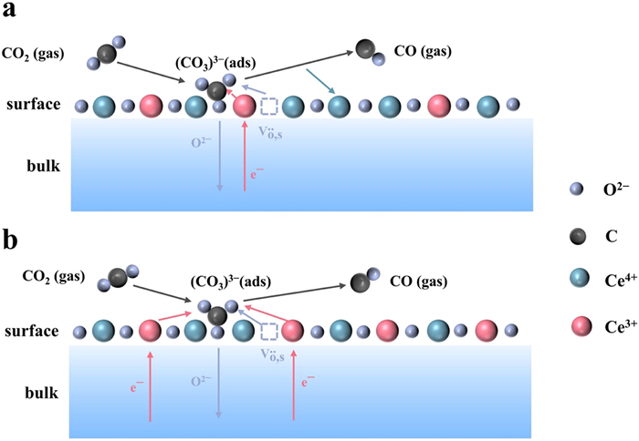
CO2 undergoes a reduction reaction at the cathode side of SOECs, and forms CO and O2−. However, the reaction pathway and mechanism have not been fully elucidated, primarily due to the high-temperature conditions and the complex material composition of SOEC, which makes the insights into this reaction challenging. In recent years, scientists have been making substantial efforts to explore the reaction mechanism for electrolyzing CO2 in SOEC using advanced techniques such as in-situ characterization and density functional theory (DFT) modeling. For instance, the in-situ X-ray photoelectron spectroscopy (XPS) and the in-situ mass spectrometry analysis enable researchers to observe the intermediate species and the reaction products in real-time, providing deeper insights into this process. Additionally, DFT simulations assist in understanding the molecular-level mechanism, guiding the design of more efficient electrocatalysts for CO2 electrolysis. Researchers like Opitz et al. have reported that under the cathodic polarization conditions, CO2 chemisorbed on the perovskite surface with oxygen vacancies, and subsequently formed carbonate intermediates [CO2−(ads), CO32−(ads)] during CO2 electrolysis on LaxSr1−xFeO3−δ electrodes by using near-ambient pressure X-ray photoelectron spectroscopy (NAPXPS) (Fig. 5a) [55]. It was proposed that the CO2 electrolysis was influenced by the transferred electrons and oxygen vacancy concentration on the electrode surface. Inspired by this study, Yang and colleagues conducted a similar research endeavor by using Raman spectroscopy [56], coupled with DFT calculations, to reveal the presence of carbonate species on the surface of LaxSr1−xFeO3−δ perovskite, and finally proposed an underlying mechanism. To be specific, CO2 molecules were initially chemisorbed onto the perovskite surface, and converted into the stably adsorbed carbonate [CO32−(ads)]. Upon accepting electrons, CO32−(ads) were further transformed into the activated bent CO2–(ads) on the surface. With further obtaining electrons, it was decomposed into the adsorbed CO(ads) and oxygen anions [O2−(ads)], eventually releasing the adsorbed CO(ads) into the gas phase (Fig. 5b). This mechanism actually confirmed that the carbonate species were the key intermediates during CO2 electrolysis. Similarly, Yi et al. utilized an environmental pressure XPS to investigate CO2 electrolysis on CeO2 electrodes [57], and found that the CO32−(ads) was the key intermediate in the reaction, and clearly described the elementary steps as follows: CO2 with oxygen ions on the CeO2 surface generated the carbonate [CO32−(ads)], and subsequently charge transfer occurred between CO32− and Ce3+, leading to the dissociation of carbonate into CO and O2−, and the simultaneous oxidation of Ce3+ to Ce4+. Finally, Ce4+ was reduced back to Ce3+ with the formation of surface oxygen vacancies (Fig. 6a). Another fundamental reaction pathway has also been proposed on Ce-based materials [58,59], where CO2 electrolysis on the cathode was initiated with the electrochemical reduction of Ce4+ to Ce3+, and then CO2 reacted with the surface O2− and Ce3+ to form the carbonate CO33−(ads), which further reacted with a second Ce3+ to produce CO and surface O2−, and concurrently oxidized Ce3+ back to Ce4+ (Fig. 6b). However, unlike the LaxSr1−xFeO3−δ electrode, Ce3+/Ce4+ in Ce-based materials directly participated the CO2 electrolysis. This difference might be attributed to the relatively weaker electron donating capability of CeO2 surface to CO2 molecules. As research continues to evolve, more mechanisms on this process are being reported. For instance, Shi et al. investigated the intermediates and possible mechanisms of CO2 conversion in P-SOEC [60], and concluded that the continuous supply of protons effectively reacted with CO32− to form —OCO— and ultimately generated CO, which was considered as a key factor in CO2 conversion and CO generation in H-SOEC. Apparently, all these studies provide deep insights into the smart strategies of high-performance SOEC electrocatalysts and their associated mechanisms.

It is worth noting that the formation of carbonates experiences the electron transfer, thereby activating CO2 on the perovskite surface, where the reaction sites were primarily controlled by the oxygen vacancies in perovskites. To efficiently achieve this, researchers have explored various strategies, such as doping [61–65], infiltration [66–68], and exsolution [69–71], high-entropy modification strategies [42,72,73], to introduce a significant number of oxygen vacancies into perovskites capable of adjusting the electronic and ionic conductivity, enhancing the CO2 adsorption capability, and ultimately improving the CO2 electrolysis performance, the CO2 conversion efficiency, and the stability. However, commercializing CO2 electrolysis in SOECs still faces great challenges related to the long-term stability and the high cost, which thus demands further investigation to enhance the economic competitiveness of CO2 electrolysis in SOECs.
CO2-H2O co-electrolysis generally occurs in two different SOEC, i.e., H-SOEC and O-SOEC [74,75]. H-SOEC and O-SOEC differ from each other mainly in electrolyte type, operating mechanism, and application scenario. H-SOEC uses a proton-conducting electrolyte, which works at lower temperatures (500–700 ℃), and is suitable for distributed energy systems and small-scale H2 production, offering a greater application flexibility. In contrast, O-SOEC uses an oxygen-ion-conducting electrolyte, which works at higher temperatures (800–1000 ℃), and is applicable to large-scale industrial applications, such as H2 production and CO2 reduction. The lower operating temperatures of H-SOEC favor material compatibility, but faces challenges with the stability of proton-conducting materials, while O-SOEC with the higher operating temperatures shows higher electrolysis efficiency, but experiences larger material stress and aging issues
Traditional syngas production routes normally include the steam reforming and the coal gasification of hydrocarbons, which result in the production of CO2 as a byproduct [76]. In contrast, using O-SOEC to simultaneously convert CO2 and H2O for syngas production stands out due to its simple adjustment of CO to H2 ratio by controlling the applied potential [12]. As a result, the co-electrolysis technology of CO2 and H2O for electrochemical CO2 conversion in SOEC has gained widespread attention. In general, pure CO2 electrolysis exhibits a relatively poor performance due to the slow CO2 diffusion, and the large activation energy. In contrast, CO2-H2O co-electrolysis presents a smaller activation energy, a lower polarization resistance, and a faster electrochemical kinetics than pure CO2 electrolysis [77]. The researchers in Idaho National Laboratory has experimentally demonstrated that the area-specific resistance (ASR) for H2O-CO2 co-electrolysis is only half that of CO2 electrolysis, and is comparable to H2O electrolysis [78]. Furthermore, simultaneously introducing H2O and CO2 can suppress the irreversible damage to the fuel electrode caused by the carbon deposition, and allow for obtaining syngas with adjustable proportions in a single reactor. However, the CO2-H2O co-electrolysis (Eq. 7) is more complex than the pure CO2 electrolysis and the H2O electrolysis due to the involvements of water-gas shift (WGS) and reverse water-gas shift (RWGS) reactions during the electrolysis process:
|
|
(7) |
Research has shown that the partial conversion of CO2 to CO is achieved through the RWGS reaction, significantly reducing the overall energy consumption for syngas production [79]. Additionally, both the RWGS and the WGS reactions occur at the cathode side, influencing the product distribution (CO and H2). By controlling the reaction conditions, such as the feed gas composition, the temperature, and the applied potential, the desired CO to H2 ratio can be accurately tailored. For instance, Wu et al. investigated the impact of different CO2/H2O ratios (10/50, 20/40, 30/30, 40/20, 50/10) on the production rates of CO and H2 at a current density of 0.51 A/cm2 (Fig. 7a). The results revealed that the CO generation rate increased with the rise of the CO2/H2O ratio, while the H2 generation rate exhibited the opposite trend, indicating that the H2/CO ratio decreased with an increase in the CO2/H2O ratio [80]. On the other hand, Deka et al. found that the H2/CO ratio in the syngas produced by CO2-H2O co-electrolysis was influenced by the operating temperature (Fig. 7b). As the temperature increased, the H2/CO ratio in the syngas decreased, attributed to the favorable nature of CO2 electrolysis over H2O electrolysis at high temperatures [81]. Meanwhile, Chen et al. investigated the effect of different applied voltages on the H2/CO ratio in syngas during CO2/H2O co-electrolysis, and observed that the syngas generation rate and the H2/CO ratio both increased upon increasing the applied potential due to the fact that the applied voltage could effectively promote the gas diffusion in the porous electrodes, thus facilitating the co-electrolysis process (Fig. 7c) [82]. Likewise, Liang et al. reported that the H2/CO ratio exhibited different preferences for reactions in various regions of current density (Fig. 7d). In the initial stage of increasing current density, H2O was directly decomposed into H2, leading to a maximum H2/CO ratio. With further increasing the current density, the H2/CO ratio decreased, possibly due to the direct electrochemical reduction of CO2 to CO [83]. Bian et al. further demonstrated, in several ways, that the output H2/CO ratio value could be regulated in a broad range from ~0.1 to ~7) by adjusting the feedstock gas ratio, the operating temperature, and the applied potential [84].
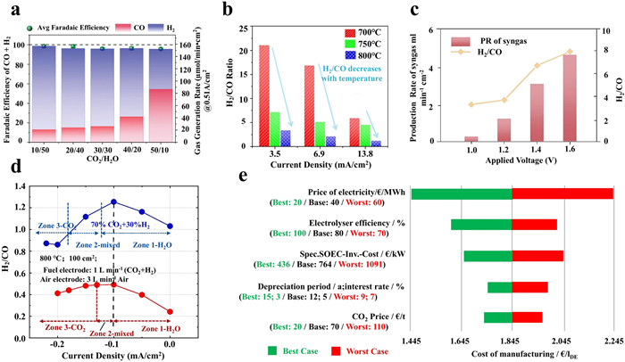
It is well known that producing various chemicals in different downstream industrial applications requires varying H2/CO ratios [12], thus achieving accurate syngas ratio is of prime significance for high-temperature CO2-H2O co-electrolysis. As mentioned earlier, adjusting the electrolysis conditions can increase H2 production, and generate syngas with a high H2/CO ratio suitable for producing long-chain hydrocarbons, such as diesel. Conversely, controlling the electrolysis conditions can also decrease H2 production, and generate syngas with a low H2/CO ratio suitable for producing short-chain hydrocarbons, such as gasoline and olefins. From a techno-economic perspective, synthesizing Fischer-Tropsch fuels based on syngas produced from CO2-H2O co-electrolysis in SOEC reduces the energy demand by 20%, and under optimal conditions, fuel production costs may decrease from 1.85 €/l to 0.94 €/l (Fig. 7e) [85]. Furthermore, the study by Fu et al. indicated that considering the power sources and O2 sales in co-electrolysis-FT processes, choosing inexpensive and low-emission nuclear power can reduce the cost of FT diesel from 1.21 €/l to 0.86 €/l [23]. These results demonstrate the great economic competitiveness of syngas production directly from CO2-H2O co-electrolysis in SOECs. Therefore, with the anticipated decline in future electricity cost, the integration of SOEC co-electrolysis technology with downstream industries is expected to become an important trend for the development of advanced energy systems.
The SOEC principle is essentially equivalent to an oxygen concentration difference cell. The significant difference in oxygen partial pressure between the reducing atmosphere at the cathode and the ambient air atmosphere at the anode leads to an open-circuit potential of up to ~1 V (e.g., 0.981 V at 800 ℃), indicating a high energy consumption. In order to reduce the energy consumption during the electrolysis process, considerable attention has been focused on the OER reaction occurred at the anode. Reductive substances (CO, H2, CH4, C2H6, C, etc.) can be utilized to replace the anodic OER and further assist electrochemical CO2 conversion. This approach not only reduces the energy barrier for oxygen ion transport, but also enables the direct generation of high-value fuels from the generated oxygen ions during the electrolysis process. However, when using H2 or CO to promote CO2 conversion via SOEC, the H2 or CO generated at the cathode is roughly equivalent to the H2 or CO consumed at the anode, resulting in net-zero economic benefits. As an alternative, the CH4-assisted CO2 electrolysis has garnered widespread attention. Both CO2 and CH4 are the major components of greenhouse gases, and are relatively inexpensive [86,87]. Utilizing CH4 to promote CO2 electrolysis in SOEC not only provides raw materials for F-T synthesis of high-value fuels, but also aids in reducing greenhouse gas emissions. From a thermodynamic perspective, due to the exothermic nature of the CH4 oxidation reaction, the required total energy, i.e., ΔH, for CH4-assisted CO2 electrolysis in SOEC is reduced as compared to the pure CO2 electrolysis (Fig. 4c). In this case, the CO2 electrolysis occurs at the cathode side and the electrochemical CH4 oxidation occurs at the anode side (Fig. 8a). As compared to the traditional CO2/CH4 reforming, reduced thermal decomposition of CH4 at the anode and CO disintegration at the cathode effectively alleviate the severe carbon deposition [88], and moreover the electrochemical pumping of oxygen ions also reduces the anodic coking phenomena.
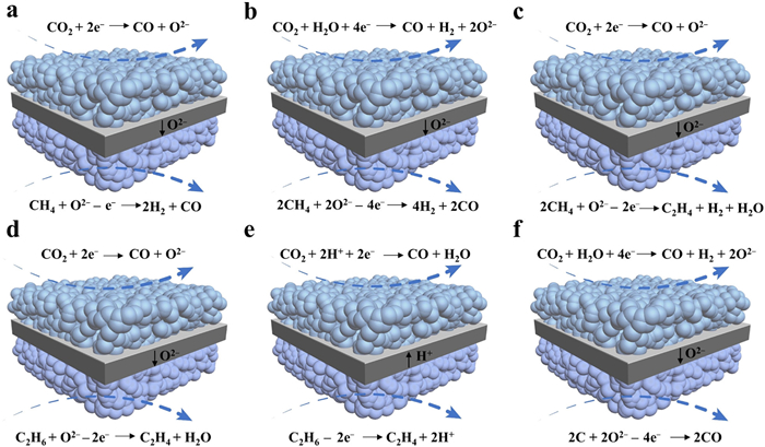
Similarly, CH4 also assists the CO2-H2O co-electrolysis process (Fig. 8b), and the partial oxidation of CH4 generates an ideal syngas mixture of H2/CO. Additionally, the POM process is a mildly exothermic reaction, with an enthalpy change of −23.1 kJ/mol at 900 ℃. This energy release compensates for parts of the energy requirement for the co-electrolysis process, thereby reducing the overall energy input. Therefore, simultaneously generating high-quality syngas on both electrodes in the F-T reaction is feasible [89]. Furthermore, the thermodynamic equilibrium calculations reveal that the ΔG for CH4-assisted CO2-H2O co-electrolysis is significantly lower than that for the traditional one. Moreover, within the practical operating temperature range of 700–900 ℃ for SOEC, the ΔG is negative, indicating that the reaction process is associated with the electricity generation (Fig. 4d). Additionally, Ni et al. systematically simulated the CH4-assisted co-electrolysis, and demonstrated that CH4 effectively lowered the equilibrium potential, thus significantly reducing the energy consumption for H2O-CO2 co-electrolysis in SOECs [27]. For example, a greatly reduced potential of 0.3 V from 1.2 V was reached to afford a current density of 0.30 A/cm2 [90], demonstrating that the CH4-assisted co-electrolysis was an efficient method for low-energy syngas production. However, the significant drawbacks of syngas production are its high energy intensity and capital costs. Directly converting CH4 into hydrocarbons would be more economical and environmentally friendly, like CH4 conversion to form C2H4 in SOEC (Fig. 8c). From the thermodynamic perspective, it still remains challenging, and only quite limited studies are currently available since CH4 is highly stable and difficult to be activated [91]. Instead, using C2H6 rather than CH4 to promote CO2 conversion for C2H4 generation is thus proposed since the thermodynamic analysis indicates that the C2H6-assisted CO2 electrolysis is more feasible and more energy efficient than the pure CO2 electrolysis (Fig. 4e). Normally, the C2H6-assisted CO2 conversion occurs mainly through two scenarios: the oxidative dehydrogenation and the non-oxidative dehydrogenation (Figs. 8d and e). The oxidative dehydrogenation of C2H6 can overcome the thermodynamic limitations, and can be carried out at low temperature [29,31]. Furthermore, the presence of oxygen can effectively suppress the coke formation, and activate C2H6 to form C2H4, but lead to the deep oxidation of C2H6 and C2H4, reducing the C2H4 selectivity [30,92,93]. In this regard, direct dehydrogenation of C2H6 can avoid these issues related to the oxidative dehydrogenation. However, its drawback is the difficult separation of products (C2H4 and H2), which lowers the conversion of C2H6 and the selectivity of C2H4. The dehydrogenation of C2H6 using a proton-conducting electrolyte can separate H2 promptly but requires catalysts resistant to the coking and highly selective to ethylene [28]. Except for the use of gaseous fuels, the co-gasification of solid carbon fuel also helps to improve CO2 conversion performance in SOEC. In the C-assisted process, the CO2-H2O co-electrolysis is carried out at the cathode to produce syngas, while C and CO2 react at the anode to generate CO (Fig. 8f). The thermodynamic calculations indicate that between 600 K and 800 K, CO2 is the main product, whereas between 973 and 1173 K, CO becomes the primary product, demonstrating that CO can be obtained at the anode side within this temperature range. Additionally, the further thermodynamic calculations (Fig. 4f) and experimental results show that the assistance for C oxidation reaction reduces the overpotential for CO2-H2O co-electrolysis in SOEC by about 1.0 V. This indicates that introducing the C-assisted reaction at the anode significantly lowers the power consumption [94]. However, due to the low catalytic activity and slow migration of the solid carbon, the kinetics of the reaction is limited, which is not conducive for its large-scale application [95]. Clearly, the processes related to the electrochemical CO2 conversion in SOEC are intricate, involving various reactants, reactions, and products. To achieve the optimal electrolysis performance, the selection of appropriate catalysts is thus highly important.
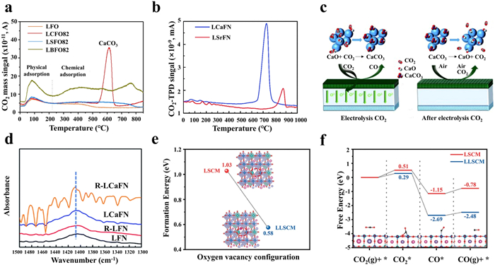
Due to the inertness of CO2 molecules and the complicated electron-coupled elementary steps, developing high-performance cathodic materials is of prime significance for CO2 conversion. Moreover, the overpotential required for CO2 dissociation is significantly higher than H2O dissociation, thus the direct CO2 electrolysis is not prominent unless the concentration of CO2 is high. Therefore, the requirements (e.g., high electronic and ion conductivity, strong CO2 adsorption capability, good resistance to coking, and desirable stability) of cathode materials for CO2-H2O co-electrolysis do not significantly differ from those for direct CO2 electrolysis. In fact, the Ni-based ceramic materials remain a popular choice for cathode, but often suffer from Ni agglomeration and carbon deposition, leading to the deteriorated cell performance, especially under high-temperature and electrolysis current conditions [96–98]. However, benefiting from the mixed ionic-electronic nature and the structural stability, perovskite oxides have been widely studied for pure CO2 electrolysis and CO2-H2O co-electrolysis [99–101]. Among them, La(Sr)Cr(Mn)O3−δ, (LaSr)(Ti)O3−δ, (LaSr)(Fe)O3−δ, Sr2Fe1.5Mo0.5O6−δ, and PrBaMn2O5+δ based perovskite oxides have been considered as potential cathodic materials due to their good stabilities and acceptable polarization resistances [102–106]. Nevertheless, the catalytic activity still falls behind those of Ni-based ceramic materials. To enhance the cathode material performance, adjusting the oxygen vacancy concentrations of these perovskite oxides work since oxygen vacancy can enhance CO2 adsorption capacity, activate CO2, improve oxygen ion conductivity, and facilitate charge transfer, thereby enhancing the catalytic activities of the catalysts. Currently, doping strategies have been widely employed to modulate oxygen vacancies in perovskite structures. Considering that the B-site transition metal elements serve as the catalytically active sites in most reactions, the B-site doping in perovskites, involving the introduction of low-valence ions (e.g., Fe, Co, Ni, and Cu), has been extensively studied [107–111]. However, the doped perovskites oxides often undergo metal/alloy nanoparticle exsolution and phase transitions in reducing atmospheres at high temperatures, leading to a rapid degradation during electrolysis [111,112]. In contrast, A-site metal elements in perovskite oxides are generally considered to less affect the catalytic activity in various catalytic processes, but the presence of A-site metals influences the overall catalytic activity by regulating the oxygen vacancy concentration, the metal-oxygen bond strength, the oxidation state, and the spin state of the B-site transition metals. Therefore, doping A-site alkaline earth elements or high redox active elements is considered as an effective alternative strategy in catalyst design. Hu and colleagues developed Ca-, Sr-, and Ba-doped La0.8A0.2FeO3−δ (A = Ca, Sr, and Ba) as SOEC cathodes, and studied their impacts on CO2 electrolysis [113]. Their findings indicated that the doped alkaline earth elements enhanced the CO2 adsorption capacity. However, under prolonged high temperature working conditions, the alkaline earth elements diffused to the surface, and formed carbonates that hindered the charge transfer and reduced the number of active sites. Notably, at 600 ℃, a sharp and pronounced desorption peak appeared on La0.8Ca0.2FeO3−δ due to the decomposition of CaCO3, whereas no such peaks were observed for the SrCO3 or BaCO3 (Fig. 9a). This observation indicated that the incorporation of Ca endowed the perovskite oxide with a self-repairing capability. Subsequently, Tian et al. investigated La0.6Ca0.4Fe0.8Ni0.2O3−δ (LCaFN) as cathode to drive pure CO2 electrolysis [114]. Under the conditions of 2.0 V and 800 ℃, the current density reached 1.41 A/cm2, coupled with a polarization resistance of only 0.04 Ω cm2. More importantly, the self-repairing mechanism of the LCaFN electrode was examined. Under conditions of 800 ℃ and 1.3 V, the LCaFN cell demonstrated a superior stability during multiple CO2 electrolysis cycles, with no significant degradation, maintaining a current density of around 0.5 A/cm2 and a low degradation rate of only 0.17% h−1. In contrast, the performance of the LSrFN cell was gradually declined, with its current density dropping from 0.31 A/cm2 to 0.22 A/cm2, resulting in a higher degradation rate of 0.57% h−1. This indicates that the LCaFN electrode significantly outperforms the LSrFN cell in terms of stability and self-repairing ability, achieving a better long-term stability. Meanwhile, Raman spectroscopy confirmed the presence of characteristic peaks in the LCaFN cathode after extended testing, supporting the self-repairing behavior (Fig. 9b). Nonetheless, the self-repairing capability of the LCaFN electrode prevented the appearance of CaCO3 peaks during 800 ℃ heat treatment in air. This is mainly caused by the diffusion of A-site Ca to the material surface, which formed CaO under prolonged high-temperature conditions, and then adsorbed CO2 to form CaCO3. Following this, the residual CaCO3 on the electrode surface was decomposed into CaO during electrolysis due to the low decomposition temperature of CaCO3 (Fig. 9c). This underscores the effectiveness of CaO as an excellent CO2 adsorbent, capable of enhancing the electrode adsorption performance, but it differs from the formation of SrCO3 and BaCO3 due to their high decomposition temperature. However, directly incorporating CaO into the electrode or infiltrating it onto the electrode material is not an effective means to improve the CO2 conversion performance [115,116]. To this end, an in-situ exsolution strategy was further employed, CaO and Ni-Fe nanoparticles were successfully formed on LCaFN cathode [117], which led to a 94% increase in CO2 electrolysis current density as compared to the pristine one. Meanwhile, under conditions of 800 ℃ and 1.3 V, the R-LCaFN cell exhibited a higher current density and a more stable performance throughout the 12 h duration. To evaluate the adsorption ability and the catalytic activity of Fe-Ni alloy and CaO on CO2 electrolysis, the X-ray absorption spectroscopy was utilized to comprehensively characterize CO2 adsorption levels and electrolysis performances on LaFe0.8Ni0.2O3 (LFN), reduced LFN, LCaFN, and reduced LCaFN samples. The findings indicated that doping Ca and the reduction conditions significantly bolstered the CO2 adsorption capacity of R-LCaFN, resulting in a gradual strengthening of the CO32− adsorption peak (Fig. 9d). Thus, the introduction of CaO with strong CO2 adsorption ability offers a promising strategy for CO2 electrolysis. Inspired by this, Chen et al. used La1−xCaxCo0.2Fe0.8O3−δ (0.2 ≤ x ≤ 0.6) as cathodes for CO2 electrolysis, achieving similar self-healing effects. The symmetric cell with La0.6Ca0.4Co0.2Fe0.8O3−δ (LCCF64) electrodes showed an electrolysis performance of 1.78 A/cm2 at 800 ℃ and 1.5 V, mainly attributed to the highly active and stable metal/perovskite interface formed by in-situ exsolved Co/CoFe nanoparticles, and the additional oxygen vacancies from the Ca2Fe2O5 phase, serving as active sites for CO2 adsorption and electrolysis. Moreover, during a 350 h test at 0.5 A/cm2 and 800 ℃, the potential showed no significant increase, indicating the excellent stability [118]. Additionally, relevant studies highlight that the introduction of low-valence cation elements into the A-site also influences CO2 electrolysis performance. For instance, Lin et al. studied perovskite La0.6−xLixSr0.4Co0.7Mn0.3O3−δ (x = 0, 0.025, 0.05, and 0.10) for CO2 conversion in SOEC [119], it was found that the SOEC with La0.55Li0.05Sr0.4Co0.7Mn0.3O3−δ cathode exhibited a current density of 0.991 A/cm2 at 1.5 V and 800 ℃, approximately 30% higher than the original sample. Additionally, this SOEC demonstrated an excellent stability during 300 h of pure CO2 electrolysis due to the fact that introducing small radius lithium element into the A-site led to the lattice mismatch, resulting in the in-situ formation of Li2CO3 under CO2 atmospheric conditions and A-site defects. Additionally, the presence of Li2CO3 and the interface formed with the perovskite oxide increased the length of the triple-phase boundary (TPB), which accelerated the CO2 adsorption, dissociation, and CO desorption processes, thereby enhancing CO2 conversion performance. In the meantime, theoretical calculations demonstrated that upon introducing lithium elements for creating additional oxygen vacancies, the ΔG for each elementary step during CO2 electrolysis significantly decreased, aligning with the experimental findings (Figs. 9e and f).
However, according to the Goldschmidt rule, excessive introduction of heteroatoms and structural defects may disrupt the integrity of the perovskite oxide structure, thereby limiting the tunability of defect engineering. Moreover, the original "A-O-A" termination of the perovskite oxide surface results in the insufficient contact between the adsorbed reactants and the catalytic active B-sites [120,121], thus affecting the conversion efficiency and constraining the reaction process. Besides, a rapid desorption of products (e.g., CO) is equally significant, since the accumulation of CO impedes not only the accessibility of adsorption-active sites for CO2, but also triggers the unfavorable Boudouard reactions [97,122]. To address these issues, studies have revealed that Ce-based materials exhibited excellent CO2 adsorption ability and catalytic activity [57,123]. For instance, Sun et al. synthesized Ce-modified La0.43Ca0.37Ti0.94Ni0.06O3−δ (LCTNi) cathode for CO2 electrolysis in SOEC [124]. Based on the DRT analysis, it was found that Ce modification facilitated the promotion of oxygen ion transport and the gas adsorption and dissociation processes, thereby further enhancing electrolysis performance. As compared to the LCTNi cells at 800 ℃ and 1.3 V under 50% CO2/50% H2 conditions, the current density increased from 0.478 A/cm2 to 0.557 A/cm2. Similarly, Zhang et al. employed an infiltration method to prepare nanostructured CeO2-modified La0.75Sr0.25Cr0.5Mn0.5O3−δ-Gd0.1Ce0.9O1.95 cathode materials, and investigated the role of CeO2 nanoparticles [125]. Research findings demonstrated that the introduction of CeO2 nanoparticles led to the augmentation of triple-phase boundaries (TPBs), enhancing CO2 adsorption capacity and promoting oxygen ion transport between the cathode and electrolyte. Building upon this, further doping of elements like Fe [126] and Mn [68] into CeO2, followed by infiltration onto the surface of La(Sr)Cr(Mn)O3−δ-based perovskites, achieved similar effects, significantly boosting CO2 electrolysis performance. Additionally, trace amounts of Ce elements can be doped into the A-site of perovskites [127], which introduced mixed oxidation states of cerium ions, consequently raising oxygen vacancy concentration, and creating favorable sites for CO2 adsorption. This not only improves the electrolysis performance, but also notably enhances the Faradaic efficiency, fully demonstrating the effectiveness of this strategy. Thus, it can be concluded that Ce-based materials hold substantial promise and potential in CO2 electrolysis.
The CH4-assisted CO2 conversion in SOEC involves the cathodic CO2-H2O co-electrolysis and the anodic POM, thus the decomposition of CO2 and the thermal cracking of CH4 mainly occur between the cathode and the anode. To achieve an optimal performance, the anode should possess a high catalytic activity and a chemical stability in the presence of hydrocarbons. Initially, Ni-based materials as SOEC anodes for CO2/CH4 oxidation electrolysis reactions were employed. For instance, Zhou et al. prepared a Ni-YSZ supported anode, and conducted CO2 electrolysis and partial oxidation of CH4 in a Ni-YSZ/YSZ/Ag-GDC cell structure [88], and found that at a current density of 500 mA/cm2, the required potential was only 0.76 V, and the ohmic resistance was 0.1 Ω cm2. This suggested that the conventional Ni-based ceramic materials exhibited a good catalytic activity for CH4 oxidation. However, due to the thermal cracking of CH4 at high temperatures, the coking issue on Ni-based ceramic materials leading to the insufficient catalytic activity and the stability degradation has limited their further applications [86,128]. Alternatively, the perovskite oxides have been demonstrated an excellent coke-resistant ability for CH4 reforming and oxidation in SOFC [129,130]. To enhance its catalytic activity, Sun et al. tested the POM catalytic activity by infiltrating Ru on LSM-YSZ [24]. As the reaction temperature increased from 800 ℃ to 900 ℃, the selectivities for CO and H2 both exceeded 99%, indicating a good POM activity on Ru-infiltrated LSM-YSZ. Similarly, Cui et al. reported a SOEC using infiltrated LSM-YSZ catalysts and Ni-SDC catalyst as anode for CH4-assisted CO2-H2O co-electrolysis. As compared to the traditional co-electrolysis mode, a relatively high current density was achieved at lower potentials [131]. For example, under conditions of 0.3 V and 850 ℃, the current density could reach 400 mA/cm2. It was also noted that the CH4 oxidation products exhibited a strong dependence on the applied current density. At a low current density of −250 mA/cm2, no CO2 formation was detected, and the H2/CO ratio was significantly greater than 2. This suggested that under a limited cathodic transport of oxygen ions, the CH4 cracking (CH4 → C + 2H2) might lead to the coking other than the POM at anode. It is known that the metal exsolve contributes to the enhanced catalytic activity of perovskite oxides, but the severe aggregation of metals at high temperatures deteriorates the long-term stability. Hence, Xie et al. employed an in-situ exsolution strategy to construct alloy/oxide interfaces on (La0.75Sr0.25)0.9(Cr0.5Mn0.5)0.9(Ni1−xCux)0.1O3−δ (LSCM-Ni1−xCux) matrix to catalyze CO2/CH4 reforming in SOEC [132], and found that the LSCM-Ni0.5Cu0.5 displayed an exceptional performance, and maintained a stability of 300 h at high temperature. This is attributed to the robust interface interaction formed by the Ni0.5Cu0.5 alloy structure (Fig. 10a), which greatly promoted the CO2 electrolysis at the cathode and the CH4 oxidation at the anode. Although Cu has a relatively lower selectivity for H2, it displays an excellent CO2/CO adsorption capability, and coking resistance, while Ni possesses a high catalytic activity but is prone to the coking. Consequently, by in-situ forming the Ni0.5Cu0.5 alloy for interface construction, the catalytic activity of Ni and Cu was effectively harnessed, which resulted in an outstanding overall performance. These studies indicated the immense potential of LSCM-based perovskite oxides for POM. Nevertheless, Bao et al. designed a series of Co/Fe co-doped La0.6Sr0.4Ti0.3Fe0.7−xCoxO3−δ (LSTFCx, x = 0–0.3) as the anodic catalysts for CH4-assisted CO2 electrolysis. By optimizing the Co/Fe ratio and controlling the size and quantity of the exsolution nanoparticles, LSTFC2 demonstrated the best electrolysis performance, which achieved a CH4 conversion rate of 86.9%, a CO selectivity of 90.1%. After a stable operation at 800 ℃ for 1250 h, only weak D and G band intensities were detected, indicating a minimal carbon deposition. Additionally, the energy consumption was significantly reduced from 3.46 kWh/m³ in traditional SOECs to 0.31 kWh/m3. These results indicated that LSTFC2 outperformed the current catalysts in terms of the anodic POM performance and stability [26]. Additionally, Sr2Fe1.5Mo0.5O6−δ (SFM), a material with an exceptional reduction/oxidation stability and a high electrical conductivity, has been used as both hydrogen and oxygen electrodes [105], and shows great potential in H2 and CH4 fuel cells [133]. Zheng et al. discovered that in SOFC mode with CH4 as the fuel, the Sr2Fe1.5Mo0.5O6−δ-Gd0.1Ce0.9O2−δ (SFM-GDC) composite hydrogen electrode suppressed the carbon deposition [134], indicating the superiority of SFM as an ideal oxygen electrode for POM in SOEC mode. Based on this, Wang et al. implemented CH4-assisted high-temperature H2O-CO2 co-electrolysis on a SFM-SDC/LSGM/SFM-SDC symmetrical cell, and revealed that at 800 ℃, a cell potential of 0.4 V yielded an electrolysis current density of 350 mA/cm2 [90]. Subsequently, Kyriakou et al. designed a symmetrical cell using La0.43Ca0.37Rh0.06Ti0.94O3−δ (LCT-Rh) with exsolve Rh nanoparticles for CH4-assisted CO2-H2O co-electrolysis, and compared its performance with a SFM-GDC symmetrical cell [135]. The results showed an 800% performance improvement in the LCT-Rh cell over SFM. Additionally, in a durability study of lasting 96 h, the LCT-Rh demonstrated a sufficient stability and a coking resistance. In specific scenarios, when directly converting CH4 to C2H4 in SOEC, the process involves the initial cleavage of C—H bonds within CH4, followed by the selective coupling of C—C bonds to generate C2H4 through a gas phase electrochemical process within a porous anode. This is a challenging process since catalytic agents with high catalytic activities are required to activate and oxidize CH4 [91]. Currently, only limited research has explored this area. For instance, Xie et al. employed a non-stoichiometric cooperative control to dope the Sr2Fe1.5+xMo0.5O6−δ (xSFMO, x = 0–0.1), and construct in-situ nanosized metal-oxide interfaces on a porous SFMO scaffold for investigating the electrochemical oxidation of CH4 at the anode and the electrolytic generation of CO from CO2 at the cathode [136]. The DFT calculations indicated that under the influence of an applied potential, the metal-oxide interface with oxygen vacancy effectively accommodated the cleavage reaction of C—H bonds (Fig. 10b), while the experimental results exhibited that with the optimal composition of 0.075Fe-SFMO-SDC, the selectivity for C2 (C2H4 + C2H6) was 75.6%, and the CH4 conversion ranged from 6.02% to 13.72% under ambient pressure and 1.2–1.6 V conditions. After undergoing a stability test of 100 h at 1.4 V and 850 ℃, the cell performance remained stable. It is evident that constructing nanosized metal-oxide interfaces not only enhances the activation activity of CH4, but also strengthens the coking resistance and the thermal stability. It is thus clear that the catalysts required for the CH4-assisted CO2 conversion need to possess a superior chemical and thermal stability, a high catalytic activity, good resistances to coking and coarsening.

Except for the CH4-assisted CO2-H2O co-electrolysis, the C2H6-assisted CO2 electrolysis in SOECs has also been studied, but is still limited, which mainly involves two primary half reactions, i.e., C2H6 dehydrogenation to C2H4 at the anode and CO2 electrolysis to CO at the cathode. However, to enable an effective use of anode catalysts for electrochemical C2H6 dehydrogenation to C2H4, a good chemical stability is the prerequisite under the reducing and oxidizing atmospheres. In addition, the thermal oxidation dehydrogenation of C2H6 faces a challenging issue due to the deep oxidation, which results in a low C2H4 selectivity. To date, researchers have been exploring suitable anode catalysts for this purpose. Among them, La0.6Sr0.4Co0.2Fe0.8O3−δ has been considered as one of the promising oxygen electrode materials for O-SOECs. To achieve the oxidative dehydrogenation of C2H6, Song et al. infiltrated γ-Al2O3 onto the surface of the La0.6Sr0.4Co0.2Fe0.8O3−δ-Sm0.2Ce0.8O2−δ anode in an O-SOEC [29], and found that the electrochemical oxidative dehydrogenation activity was significantly enhanced, and a high C2H4 selectivity of 92.5% was achieved. Moreover, the highest C2H6 conversion rate reached 29.1%, and no coking phenomenon was observed after 200 h of stability test at 600 ℃. This could be attributed to the infiltration of external Al3+ ions into the Al-O-Fe structure, where they combined with Fe, and led to an enrichment of electron density near the Fermi level of Fe, thus favoring the conversion of C2H6 (Fig. 10c). Additionally, Sun et al. developed an in-situ self-assembled multiphase nanocomposite anode, i.e., NiFe-MnO-Ce0.6Mn0.3Fe0.1O2−δ (NiFe-MnO-CMF), with an inverse oxide/metal interface for C2H6 oxidative dehydrogenation. At 700 ℃ and 1.8 V, the C2H6 conversion reached 52.23% with a C2H4 selectivity of 94.11%, maintaining a stability of 120 h at 700 ℃ [92]. Although the C2H4 selectivity was slightly higher than that reported by Song et al., its stability was significantly lower, indicating that the La0.6Sr0.4Co0.2Fe0.8O3−δ-Sm0.2Ce0.8O2−δ anode material infiltrated with γ-Al2O3 demonstrated a better long-term stability than NiFe-MnO-CMF. Inspired by this, a symmetric SOEC with a YSZ electrolyte and a porous single-crystal CeO2 electrode was constructed. The anode was used for the electrochemical oxidative dehydrogenation of C2H6 [31], and the cathode performed CO2 electrolysis. At 600 ℃, after approximately 300 operating cycles and 10 redox cycles, the selectivity for C2H4 reached 94.8% (Figs. 10d and e), beyond the results of these two efforts, mainly attributed to the presence of specific active oxygen on the surface of CeO2 anode, which activated the C—H bonds in C2H6 molecules, thereby enhancing the C2H4 selectivity. Furthermore, the content of the adsorbed oxygen species (O−, 531.5 eV) decreased from 15.6% (+1.5 V) to 13.5% (+2.0 V), which reduced the extent of deep C2H6 oxidation and further strengthened C2H4 selectivity. To further enhance the C2H4 selectivity, a Nb1.33(Ti0.8Mn0.2)0.67O4−δ anode exsolved with NixCu1−x alloy was proposed to drive non-oxidative dehydrogenation of C2H6 coupled with CO2 electrolysis in a H-SOEC [28]. At 0.8 V, the highest C2H6 conversion reached 75.2%, and C2H4 selectivity approached 100%. As compared to previous studies, this material further improved the C2H4 selectivity due to the strong metal-oxide interface interaction, which significantly enhanced the stability and the coking resistance in high-temperature environments. Despite achieving some groundbreaking results in developing SOEC anode materials for C2H6 oxidation, the associated reaction mechanisms still remain insufficiently understood. With one step forward, Sr2Ti0.8Co0.6Fe0.6O6−δ as the symmetric electrode material was adopted, and the evolution of oxygen at the anode surface was successfully visualized using the synchrotron-based ambient pressure X-ray photoelectron spectroscopy and the adsorption spectroscopy (APXPS/XAS) [137]. Additionally, theoretical calculations revealed the intrinsic impact of different surface oxygen species on the C2H6 dehydrogenation. Notably, the C2H4 yield reached 66.3% at 800 ℃ (Fig. 10f), one of the highest yields reported to date, which undoubtedly provided theoretical guidance for future research on the catalytic design for anodic C2H6 dehydrogenation.
The environmental issues drive us to seek approaches to reducing CO2 emissions from fossil fuels, among which electrochemical CO2 conversion in SOECs offers a highly promising carbon reduction technology by efficiently producing sustainable fuels such as CO, syngas, and light hydrocarbons. This review comprehensively explores the latest advances on electrochemical CO2 conversion within SOECs, mainly including the fundamentals, specific applications, and material selection oriented to various applications. In the long term, utilizing SOECs for CO2 conversion to produce sustainable fuels is a promising pathway for high-temperature electrolysis. However, the main obstacles to its rapid development are the long-term stability and the economic feasibility. To overcome these challenges, future studies are suggested as follows:
(1) To date, theoretical computations (i.e., DFT calculations and molecular dynamics simulation) have been widely used to uncover the structure-performance inter-relationships of electrocatalysts from perspectives of thermodynamics and kinetics, which greatly helps us to understand the catalysis mechanism and guide the following catalyst design. Besides, artificial intelligence (AI) and machine learning (ML) as emerging advanced technologies have been gradually applied to rapidly and effectively predict and screen catalysts for various applications, e.g., OER [138], HER [139], Oxygen reduction reaction (ORR) [140], CO2RR [141,142], which stimulate researchers to use these exciting techniques for screening SOEC electrocatalysts. Moreover, the theoretical computations, coupled with AI and ML, offer promising means to overcome the limitations of current electrode materials.
(2) Advanced in-situ characterization techniques could directly observe the catalytic process and achieve various data and information in real time, which provides technical support for analysis of intermediate states and long-term cell degradation. Techniques, such as in-situ FTIR, provide an important window for real-time monitoring of surface chemical reactions and interface reactions in SOECs, helping researchers to better understand the chemical changes occurring in electrodes and electrolytes during operation. At the same time, in-situ XRD provides real-time crystal structure information, allowing researcher to deeply investigate the behavior of SOEC materials under working conditions, particularly in processes related to the phase transition, stress, lattice distortion, and degradation. In addition, in-situ XPS offers the ability to monitor surface chemical states and redox reactions in real-time, making it suitable for studying the surface chemistry, interface reaction, elemental diffusion, and degradation mechanisms of electrodes and electrolytes. Likewise, in-situ TEM provides a direct observation window at atomic resolution for structural changes in SOEC materials, revealing key processes such as material degradation, phase transition, and interface reaction by monitoring the structural evolution of electrodes, electrolytes, and their interfaces during operation. All of these, as useful instructions for further exploring advanced electrode materials, help us to well understand the mechanism of the cell degradation.
(3) To achieve the production of high-value fuels, it is necessary to improve the economic and technical feasibility of CO2 conversion in SOECs, further promoting its widespread application. Although the technology shows great potential, commercialization faces significant challenges, particularly as stack costs account for the majority of SOEC system capital expenditures. Using low-cost materials can effectively reduce the stack costs, but experimental evidence is still needed to verify their performance and stability. Large-scale automated production is expected to significantly reduce the capital investment, and high-efficiency, high-quality cells manufactured by automated factories will meet the growing demand for CO2 reduction. In addition, advanced manufacturing technologies will further reduce the scale and the cost. Thus integrating SOEC systems with upstream renewable energy harvesting and downstream fuel storage and consumption systems to produce high-value fuels is a highly promising pathway, which requires the global governmental support and the collaborative efforts.
The authors declare no competing financial interest.
Ming Yang: Writing – original draft, Investigation, Conceptualization. Lin-Bo Liu: Validation. Shuo Liu: Methodology. Yan Li: Investigation. Biao Ouyang: Visualization. Xian-Zhu Fu: Visualization. Jing-Li Luo: Resources. Yifei Sun: Supervision. Subiao Liu: Writing – review & editing, Resources, Project administration, Funding acquisition.
This work is supported by the Pilot Group Program of the Research Fund for International Senior Scientists (No. 22350710789), the National Natural Science Foundation of China (NSFC, No. 22109182), the Natural Science Foundation of Hunan Province, China (No. 2022JJ30684) and the Start-up Funding of Central South University (No. 206030104). This work is supported in part by the High-Performance Computing Center of Central South University.
L.L. Guarieiro, J.P. dos Anjos, L.A. de Silva, et al., Chem. Soc. 33 (2022) 844–869.
G.P. Hammond, Process Saf. Environ. Prot. 78 (2000) 304–323. doi: 10.1205/095758200530826
B.D. Solomon, K. Krishna, Energy Policy 39 (2011) 7422–7431. doi: 10.1016/j.enpol.2011.09.009
IEA, CO2 Emissions in 2023, IEA, Paris, 2023.
D.M. Koshy, S.S. Nathan, A.S. Asundi, Angew. Chem. Int. Ed. 133 (2021) 17613–17621. doi: 10.1002/ange.202101326
Y. Li, L. Zhang, B. Yu, J. Zhu, C. Wu, Engineering 21 (2023) 101–114. doi: 10.1016/j.eng.2022.02.016
H. Wang, Nano Res. 15 (2022) 2834–2854. doi: 10.1007/s12274-021-3984-9
C.D. Windle, R.N. Perutz, Coord. Chem. Rev. 256 (2012) 2562–2570. doi: 10.1016/j.ccr.2012.03.010
W. Zhang, Y. Hu, L. Ma, et al., Adv. Sci. 5 (2018) 1700275. doi: 10.1002/advs.201700275
N. Han, R.Z. Ren, M.J. Ma, et al., Chin. Chem. Lett. 33 (2022) 2658–2662. doi: 10.1016/j.cclet.2021.09.100
J. Qiao, Y. Liu, F. Hong, J. Zhang, Chem. Soc. Rev. 43 (2014) 631–675. doi: 10.1039/C3CS60323G
A. Hauch, R. Küngas, P. Blennow, et al., Science 370 (2020) eaba6118. doi: 10.1126/science.aba6118
W. Li, J.L. Luo, Electrochem. Energy Rev. 4 (2021) 518–544. doi: 10.1007/s41918-021-00099-2
Y. Peng, Y. Song, I. Razanau, et al., J. Energy Chem. 100 (2025) 286–308. doi: 10.1016/j.jechem.2024.08.050
K. Sridhar, B. Vaniman, Solid State Ionics 93 (1997) 321–328. doi: 10.1016/S0167-2738(96)00513-9
H. Chandler, F. Pollara, Oxygen regeneration from solid electrolytic reduction of carbon dioxide for space cabin atmosphere, in: H. Chandler (Ed. ), Oxygen Regeneration in a Solid Electrolyte System, Elsevier, New York, 1966, pp. 5–36.
S.D. Ebbesen, M. Mogensen, J. Power Sources 193 (2009) 349–358. doi: 10.1016/j.jpowsour.2009.02.093
X. Yue, J.T.S. Irvine, Solid State Ionics 225 (2012) 131–135. doi: 10.1016/j.ssi.2012.06.015
Y. Li, Y. Gan, Y. Wang, K. Xie, Y. Wu, Int. J. Hydrogen Energy 38 (2013) 10196–10207. doi: 10.1016/j.ijhydene.2013.06.057
D. Neagu, G. Tsekouras, D.N. Miller, H. Menard, J.T. Irvine, Nat. Chem. 5 (2013) 916–923. doi: 10.1038/nchem.1773
C.M. Stoots, Idaho National Lab. (INL), Idaho Falls, ID (United States), 2006.
L. Chen, F. Chen, C. Xia, Energy Environ. Sci. 7 (2014) 4018–4022. doi: 10.1039/C4EE02786H
Q. Fu, C. Mabilat, M. Zahid, A. Brisse, L. Gautier, Energy Environ. Sci. 3 (2010) 1382–1397. doi: 10.1039/c0ee00092b
Y.F. Sun, Y.Y. Wu, Y.Q. Zhang, et al., Chem. Commun. 52 (2016) 13687–13690. doi: 10.1039/C6CC03503E
J. Lu, Y. Hu, M. Zhang, Q. Hu, J. Wu, Int. J. Hydrogen Energy 55 (2024) 786–795. doi: 10.1016/j.ijhydene.2023.11.247
Y. Guo, S. Wang, R. Li, et al., Joule 7 (2024) 2016–2032.
H. Xu, B. Chen, J. Irvine, M. Ni, Int. J. Hydrogen Energy 41 (2016) 21839–21849. doi: 10.1016/j.ijhydene.2016.10.026
X. Zhang, L. Ye, H. Li, F. Chen, K. Xie, ACS Catal. 10 (2020) 3505–3513. doi: 10.1021/acscatal.9b05409
Y. Song, L. Lin, W. Feng, et al., Angew. Chem. Int. Ed. 58 (2019) 16043–16046. doi: 10.1002/anie.201908388
A. Tsyganok, P.J.E. Harlick, A. Sayari, Catal. Commun. 8 (2007) 850–854. doi: 10.1016/j.catcom.2006.09.010
L. Ye, X. Duan, K. Xie, Angew. Chem. Int. Ed. 60 (2021) 21746–21750. doi: 10.1002/anie.202109355
X. Hou, Y. Jiang, K. Wei, et al., Chem. Rev. 124 (2024) 5119–5166. doi: 10.1021/acs.chemrev.3c00760
I. Jang, J.S.A. Carneiro, J.O. Crawford, et al., Chem. Rev. 124 (2024) 8233–8306. doi: 10.1021/acs.chemrev.4c00008
H. Liu, M. Yu, X. Tong, Q. Wang, M. Chen, Chem. Rev. 124 (2024) 10509–10576. doi: 10.1021/acs.chemrev.3c00795
J. Cao, Y. Ji, Z. Shao, Chem. Soc. Rev. 53 (2024) 450–501. doi: 10.1039/d3cs00303e
S.E. Wolf, F.E. Winterhalder, V. Vibhu, et al., J. Mater. Chem. A 11 (2023) 17977–18028. doi: 10.1039/d3ta02161k
C. Sun, J.A. Alonso, J. Bian, Adv. Energy Mater. 11 (2020) 200459.
Z. Wang, Y. Wang, Z. Jin, et al., Adv. Funct. Mater. 34 (2024) 2404051. doi: 10.1002/adfm.202404051
X. Xu, Y. Zhong, Z. Shao, Trends Chem. 1 (2019) 410–424. doi: 10.1016/j.trechm.2019.05.006
X. Xu, Y. Pan, Y. Zhong, R. Ran, Z. Shao, Mater. Horiz. 7 (2020) 2519–2565. doi: 10.1039/d0mh00477d
R. Xu, S. Liu, M. Yang, et al., Chem. Sci. 15 (2024) 11166–11187. doi: 10.1039/d4sc03306j
M. Yang, S. Liu, X. Shen, et al., ACS Energy Lett. 9 (2024) 3818–3827. doi: 10.1021/acsenergylett.4c01447
M. Stanbury, J.D. Compain, M. Trejo, et al., Electrochim. Acta 240 (2017) 288–299. doi: 10.1016/j.electacta.2017.04.080
Y. Zheng, W. Zhang, Y. Li, et al., Nano Energy 40 (2017) 512–539. doi: 10.1016/j.nanoen.2017.08.049
K. Chen, S.P. Jiang, J. Electrochem. Soc. 163 (2016) F3070–F3083. doi: 10.1149/2.0101611jes
M.S. Sohal, J.E. O'Brien, C.M. Stoots, et al., J. Fuel Cell Sci. Technol. 9 (2012) 011017. doi: 10.1115/1.4003787
P.A. Kempler, A.C. Nielander, Nat. Commun. 14 (2023) 1158. doi: 10.1038/s41467-023-36880-8
P.S. Gaikwad, K. Mondal, Y.K. Shin, et al., npj Comput. Mater. 9 (2023) 149. doi: 10.1038/s41524-023-01044-1
M.G. Sahini, S.D. Lupyana, Mate. Sci. Eng. B 292 (2023) 116415. doi: 10.1016/j.mseb.2023.116415
L.M. Ushkalov, E. М. Brodnikovs'kyi, N. О. Lysunenko, et al., Mat. Sci. 51 (2016) 555–562. doi: 10.1007/s11003-016-9875-7
J.R. Mawdsley, J.D. Carter, A.J. Kropf, et al., Int. J. Hydrogen Energy 34 (2009) 4198–4207. doi: 10.1016/j.ijhydene.2008.07.061
A.V. Virkar, Int. J. Hydrogen Energy 35 (2010) 9527–9543. doi: 10.1016/j.ijhydene.2010.06.058
S.D. Ebbesen, C. Graves, A. Hauch, et al., J. Electrochem. Soc. 157 (2010) B1419. doi: 10.1149/1.3464804
S.D. Ebbesen, M. Mogensen, Electrochem. Solid-State Lett. 13 (2010) B106. doi: 10.1149/1.3455882
A.K. Opitz, A. Nenning, C. Rameshan, et al., ACS Appl. Mater. Interfaces 9 (2017) 35847–35860. doi: 10.1021/acsami.7b10673
Y. Yang, Y. Li, Y. Jiang, et al., Electrochim. Acta 284 (2018) 159–167. doi: 10.1016/j.electacta.2018.07.187
Y. Yu, B. Mao, A. Geller, et al., Phys. Chem. Chem. Phys. 16 (2014) 11633–11639. doi: 10.1039/C4CP01054J
Z.A. Feng, M.L. Machala, W.C. Chueh, Phys. Chem. Chem. Phys. 17 (2015) 12273–12281. doi: 10.1039/C5CP00114E
E.M. Sala, N. Mazzanti, M.B. Mogensen, et al., Solid State Ionics 375 (2022) 115833. doi: 10.1016/j.ssi.2021.115833
N. Shi, Y. Xie, D. Huan, et al., J. Mater. Chem. A 7 (2019) 4855–4864. doi: 10.1039/c8ta12458b
J. Lu, S. Li, S. Tao, T. Zhang, K. Xie, Int. J. Hydrogen Energy 42 (2017) 8197–8206. doi: 10.1016/j.ijhydene.2017.01.182
W. Qi, Y. Gan, D. Yin, et al., J. Mater. Chem. A 2 (2014) 6904–6915. doi: 10.1039/C4TA00344F
S. Liu, Q. Liu, J.L. Luo, J. Mater. Chem. A 5 (2017) 2673–2680. doi: 10.1039/C6TA09151B
L. Ye, M. Zhang, P. Huang, et al., Nat. Commun. 8 (2017) 14785. doi: 10.1038/ncomms14785
Y. Zhou, Z. Zhou, Y. Song, et al., Nano Energy 50 (2018) 43–51. doi: 10.1016/j.nanoen.2018.04.054
J. Xu, X. Zhou, L. Pan, M. Wu, K. Sun, J. Power Sources 371 (2017) 1–9. doi: 10.1016/j.jpowsour.2017.10.016
M. Wu, X. Zhou, J. Xu, et al., J. Power Sources 451 (2020) 227334. doi: 10.1016/j.jpowsour.2019.227334
X. Zhang, Y. Song, F. Guan, et al., J. Catal. 359 (2018) 8–16. doi: 10.1016/j.jcat.2017.12.027
S. Liu, Q. Liu, J.L. Luo, ACS Catal. 6 (2016) 6219–6228. doi: 10.1021/acscatal.6b01555
J. Li, Q. Liu, Y. Song, et al., Green Chem. Eng. 3 (2022) 250–258. doi: 10.1016/j.gce.2021.12.011
H. Lv, T. Liu, X. Zhang, et al., Angew. Chem. Int. Ed. 59 (2020) 15968–15973. doi: 10.1002/anie.202006536
Z. Wang, T. Tan, K. Du, et al., Adv. Mater. 36 (2024) 2312119. doi: 10.1002/adma.202312119
X. Li, T. Chen, C. Wang, et al., Adv. Funct. Mater. 3 (2024) 2411216.
Y. Zheng, Z. Chen, J. Zhang, Electrochem. Energy Rev. 4 (2021) 508–517. doi: 10.1007/s41918-021-00097-4
Z. Zhan, L. Zhao, J. Power Sources 195 (2010) 7250–7254. doi: 10.1016/j.jpowsour.2010.05.037
S.A.A. Naqvi, M.T. Mehran, R.H. Song, et al., Chem. Eng. J. 300 (2016) 384–393. doi: 10.1016/j.cej.2016.04.095
S. -W. Kim, H. Kim, K.J. Yoon, et al., J. Power Sources 280 (2015) 630–639. doi: 10.1016/j.jpowsour.2015.01.083
C. Stoots, J. O'Brien, J. Hartvigsen, Int. J. Hydrogen Energy 34 (2009) 4208–4215. doi: 10.1016/j.ijhydene.2008.08.029
M. Ni, J. Power Sources 202 (2012) 209–216. doi: 10.1016/j.jpowsour.2011.11.080
K.T. Wu, J. Matsuda, A. Staykov, T. Ishihara, Adv. Energy Mater. 13 (2023) 2301042. doi: 10.1002/aenm.202301042
D.J. Deka, J. Kim, S. Gunduz, et al., Appl. Catal. A 602 (2020) 117697. doi: 10.1016/j.apcata.2020.117697
J. Li, X. Sun, Y. Ye, M. Zhou, Y. Chen, Energy Fuels 37 (2023) 19230–19238. doi: 10.1021/acs.energyfuels.3c03312
J. Liang, Y. Wang, J. Zhu, et al., Energy Convers. Manag. 277 (2023) 116621. doi: 10.1016/j.enconman.2022.116621
L. Bian, C. Duan, L. Wang, et al., J. Power Sources 482 (2021) 228887. doi: 10.1016/j.jpowsour.2020.228887
R. Peters, N. Wegener, R.C. Samsun, et al., Processes 10 (2022) 699. doi: 10.3390/pr10040699
F. Liu, Z. Chen, H. Zhou, et al., J. Power Sources 609 (2024) 234703. doi: 10.1016/j.jpowsour.2024.234703
W. Wang, C. Su, Y. Wu, R. Ran, Z. Shao, Chem. Rev. 113 (2013) 8104–8151. doi: 10.1021/cr300491e
M. Zhou, Z. Liu, X. Yan, et al., J. Electrochem. Soc. 169 (2022) 034502. doi: 10.1149/1945-7111/ac554d
Y. Wang, T. Liu, L. Lei, F. Chen, J. Power Sources 344 (2017) 119–127. doi: 10.1016/j.jpowsour.2017.01.096
Y. Wang, T. Liu, S. Fang, et al., J. Power Sources 277 (2015) 261–267. doi: 10.1016/j.jpowsour.2014.11.092
P. Schwach, X. Pan, X. Bao, Chem. Rev. 117 (2017) 8497–8520. doi: 10.1021/acs.chemrev.6b00715
S. Zhang, C. Xu, R. Ren, et al., ACS Appl. Mater. Interfaces 16 (2024) 3451–3459. doi: 10.1021/acsami.3c16107
M. Qin, S. Zhang, W. Sun, et al., Ceram. Int. 49 (2023) 30178–30186. doi: 10.1016/j.ceramint.2023.06.274
L. Lei, Y. Wang, S. Fang, et al., Appl. Energy 173 (2016) 52–58. doi: 10.1016/j.apenergy.2016.03.116
B. Ewan, O. Adeniyi, Energies 6 (2013) 1657–1668. doi: 10.3390/en6031657
T.L. Skafte, P. Blennow, J. Hjelm, C. Graves, J. Power Sources 373 (2018) 54–60. doi: 10.1016/j.jpowsour.2017.10.097
V. Duboviks, M. Lomberg, R. Maher, et al., J. Power Sources 293 (2015) 912–921. doi: 10.1016/j.jpowsour.2015.06.003
Y. Tao, S.D. Ebbesen, M.B. Mogensen, J. Electrochem. Soc. 161 (2014) F337–F343. doi: 10.1149/2.079403jes
Y.H. Niu, W.R. Huo, Y.D. Yu, et al., Chin. Chem. Lett. 33 (2022) 674–682. doi: 10.1016/j.cclet.2021.07.037
X.X. Zhang, B. Liu, Y.L. Yang, et al., Chin. Chem. Lett. 34 (2023) 108035. doi: 10.1016/j.cclet.2022.108035
P. Zhang, J. Chang, F. Qu, et al., ACS Sustain. Chem. Eng. 12 (2024) 1561–1572. doi: 10.1021/acssuschemeng.3c06791
F. Bidrawn, G. Kim, G. Corre, et al., Electrochem. Solid-State Lett. 11 (2008) B167. doi: 10.1149/1.2943664
L. Ye, C. Pan, M. Zhang, et al., ACS Appl. Mater. Interfaces 9 (2017) 25350–25357. doi: 10.1021/acsami.7b07039
M. Pidburtnyi, B. Zanca, C. Coppex, S. Jimenez-Villegas, V. Thangadurai, Chem. Mater. 33 (2021) 4249–4268. doi: 10.1021/acs.chemmater.1c00771
P. Qiu, S. Sun, J. Li, L. Jia, Sep. Purif. Technol. 298 (2022) 121581. doi: 10.1016/j.seppur.2022.121581
T.H. Shin, J.H. Myung, M. Verbraeken, G. Kim, J.T. Irvine, Faraday Discuss. 182 (2015) 227–239. doi: 10.1039/C5FD00025D
J. Zhu, W. Zhang, Y. Li, et al., Appl. Catal. B 268 (2020) 118389. doi: 10.1016/j.apcatb.2019.118389
D.J. Deka, S. Gunduz, T. Fitzgerald, J.T. Miller, Appl. Catal. B 248 (2019) 487–503. doi: 10.1016/j.apcatb.2019.02.045
V.S. Kudyakova, B.V. Politov, O.V. Merkulov, A.Y. Suntsov, Mater. Res. Bull. 149 (2022) 111717. doi: 10.1016/j.materresbull.2021.111717
G. Tsekouras, D. Neagu, J.T.S. Irvine, Energy Environ. Sci. 6 (2013) 256–266. doi: 10.1039/C2EE22547F
C. Xu, S. Zhen, R. Ren, et al., Chem. Commun. 55 (2019) 8009–8012. doi: 10.1039/c9cc03455b
F. He, M. Hou, F. Zhu, et al., Adv. Energy Mater. 12 (2022) 2202175. doi: 10.1002/aenm.202202175
S. Hu, L. Zhang, H. Liu, et al., J. Power Sources 443 (2019) 227268. doi: 10.1016/j.jpowsour.2019.227268
Y. Tian, L. Zhang, Y. Liu, et al., J. Mater. Chem. A 7 (2019) 6395–6400. doi: 10.1039/c9ta00643e
M. Asamoto, S. Miyake, K. Sugihara, H. Yahiro, Electrochem. Commun. 11 (2009) 1508–1511. doi: 10.1016/j.elecom.2009.05.042
T. Takeguchi, Y. Kani, T. Yano, et al., J. Power Sources 112 (2002) 588–595. doi: 10.1016/S0378-7753(02)00471-8
Y. Tian, Y. Liu, A. Naden, et al., J. Mater. Chem. A 8 (2020) 14895–14899. doi: 10.1039/d0ta05518b
H. Li, W. Wang, L. Wang, et al., ACS Appl. Mater. Interfaces 15 (2023) 43732–43744. doi: 10.1021/acsami.3c08561
W. Lin, W. Su, Y. Li, et al., Small 19 (2023) e2303305. doi: 10.1002/smll.202303305
D. Neagu, T.S. Oh, D.N. Miller, et al., Nat. Commun. 6 (2015) 8120. doi: 10.1038/ncomms9120
A. Staykov, H. Tellez, J. Druce, et al., Sci. Technol. Adv. Mater. 19 (2018) 221–230. doi: 10.1080/14686996.2018.1440136
J. Yan, H. Chen, E. Dogdibegovic, et al., J. Power Sources 252 (2014) 79–84. doi: 10.1016/j.jpowsour.2013.11.047
T.L. Skafte, Z. Guan, M.L. Machala, et al., Nat. Energy 4 (2019) 846–855. doi: 10.1038/s41560-019-0457-4
Z. Li, M. Peng, Y. Zhu, et al., J. Mater. Chem. A 10 (2022) 20350–20364. doi: 10.1039/d2ta05827h
L. Zhang, S. Hu, W. Li, et al., ACS Sustain. Chem. Eng. 7 (2019) 9629–9636. doi: 10.1021/acssuschemeng.9b01183
S. Lee, M. Kim, K.T. Lee, J.T.S. Irvine, T.H. Shin, Adv. Energy Mater. 11 (2021) 2100339. doi: 10.1002/aenm.202100339
Y.Q. Zhang, J.H. Li, Y.F. Sun, B. Hua, J.L. Luo, ACS Appl. Mater. Interfaces 8 (2016) 6457–6463. doi: 10.1021/acsami.5b11979
J. Ni, L. Chen, J. Lin, S. Kawi, Nano Energy 1 (2012) 674–686. doi: 10.1016/j.nanoen.2012.07.011
S. Tao, J.T. Irvine, Nat. Mater. 2 (2003) 320–323. doi: 10.1038/nmat871
X. Yue, J.T.S. Irvine, J. Electrochem. Soc. 159 (2012) F442–F448. doi: 10.1149/2.040208jes
C. Cui, Y. Wang, Y. Tong, et al., Int. J. Hydrogen Energy 46 (2021) 20305–20312. doi: 10.1016/j.ijhydene.2021.03.177
J. Lu, C. Zhu, C. Pan, et al., Sci. Adv. 4 (2018) eaar5100. doi: 10.1126/sciadv.aar5100
Z. Wang, Y. Tian, Y. Li, J. Power Sources 196 (2011) 6104–6109. doi: 10.1016/j.jpowsour.2011.03.053
K. Zheng, K. Świerczek, N.M. Carcases, T. Norby, ECS Trans. 64 (2014) 103. doi: 10.1149/06402.0103ecst
V. Kyriakou, D. Neagu, G. Zafeiropoulos, et al., ACS Catal. 10 (2019) 1278–1288.
C. Zhu, S. Hou, X. Hu, et al., Nat. Commun. 10 (2019) 1173. doi: 10.1038/s41467-019-09083-3
X. Sun, H. Yang, B. Chen, et al., ACS Catal. 14 (2024) 5827–5837. doi: 10.1021/acscatal.3c04731
M. Karthikeyan, D.M. Mahapatra, A.S.A. Razak, et al., Catal. Rev. 4 (2022) 997–1027.
X. Zhang, J. Liu, R. Li, et al., J. Colloid Interface Sci. 645 (2023) 956–963. doi: 10.1016/j.jcis.2023.05.011
L.E. Lucchetti, J.M. de Almeida, S. Siahrostami, EES Catal. 2 (2024) 1037–1058. doi: 10.1039/d4ey00104d
M. Sun, B. Huang, M, Adv. Energy Mater. 13 (2023) 2301948. doi: 10.1002/aenm.202301948
D. Roy, A. Das, S. Manna, B. Pathak, J. Phys. Chem. C 127 (2023) 871–881. doi: 10.1021/acs.jpcc.2c06924

Figure 1 (a) Comparison of various CO2 electrolysis technologies Reprinted with permission [12]. Copyright 2020, American Association for the Advancement of Science. (b) The artificial carbon cycle with the aid of SOEC.

Figure 2 (a) The timeline of major developments for electrosynthesizing high-value fuels from CO2 in various SOECs (source: Web of Science, 2024−09). (b) The number of publications and citations by searching the keywords of "CO2 electrolysis" and "solid oxide electrolysis cell" from 2000 to 2024.09. (c) Different applications for CO2 conversion.

Figure 3 Working principles of (a) O-SOEC for CO2 electrolysis. (b) H-SOEC for CO2-H2O electrolysis.

Figure 4 Energy demands for (a) pure CO2 electrolysis, (b) CO2-H2O co-electrolysis, (c) POM-assisted CO2 electrolysis, (d) CH4-assisted CO2-H2O co-electrolysis, (e) C2H6-assisted CO2 electrolysis, and (f) C-assisted CO2-H2O co-electrolysis. ΔH, ΔG and ΔS values were calculated by HSC 6.0 software.

Figure 5 Two proposed mechanisms for pure CO2 electrolysis on LaxSr1−xFeO3−δ in SOECs: (a) CO2 combines with oxygen vacancies and electrons, forming bidentate carbonate, (b) CO2 directly reacts with lattice oxygen ions, forming carbonate.

Figure 6 Two proposed mechanisms for pure CO2 electrolysis on Ce-based materials in SOECs: (a) Relying on the oxidation of Ce3+ to Ce4+, (b) starting from the reduction of Ce4+ to Ce3+, with Ce3+ at the core of the CO2 reduction reaction.

Figure 7 (a) The gas generation rates of CO and H2 with different CO2/H2O feed ratios. Reprinted with permission [80]. Copyright 2023, Wiley. (b) The impact of different temperatures on the H2/CO ratio. Reprinted with permission [81]. Copyright 2020, Elsevier. (c) Variation of syngas yield and H2/CO ratio at different voltages. Reprinted with permission [82]. Copyright 2023, American Chemical Society. (d) The impact of varying current density on H2/CO. Reprinted with permission [83]. Copyright 2023, Elsevier. (e) The Tornado chart illustrating the impact of various cost factors on the levelized electricity cost. Reprinted with permission [85]. Copyright 2022, MDPI (Basel, Switzerland).

Figure 8 Schematic diagrams of (a) POM-assisted CO2 electrolysis, (b) POM-assisted CO2-H2O co-electrolysis, (c) CH4 oxidation-assisted CO2 electrolysis, (d) C2H6 oxidative dehydrogenation-assisted CO2 electrolysis, (e) C2H6 non-oxidative dehydrogenation-assisted CO2 electrolysis, and (f) C-assisted CO2-H2O co-electrolysis.

Figure 9 (a) The adsorption capacity of LaFeO3−δ doped with different alkaline earth elements (Ca, Sr, and Ba) for CO2 electrolysis. Reprinted with permission [113]. Copyright 2019, Elsevier. (b) The adsorption capacity of LCaFN and LSrFN for CO2 electrolysis. (c) Schematic diagram of the self-recovery principle of LCaFN electrode for CO2 electrolysis. Reprinted with permission [114]. Copyright 2019, Royal Society of Chemistry. (d) In situ diffuse reflectance infrared Fourier transform spectroscopy (DRIFTS) for CO2 electrolysis on LaFe0.8Ni0.2O3 (LFN), R-LFN, LCaFN, and R-LCaFN. Reprinted with permission [117]. Copyright 2020, Royal Society of Chemistry. (e) Free energy diagrams for electrolyzing CO2, and (f) oxygen vacancy formation energy for LSCM and LLSCM. Reprinted with permission [119]. Copyright 2023, Wiley.

Figure 10 (a) The most stable adsorption configuration of CO2 on the surface of (Ni-Cu)/LCO(001) system. Reprinted with permission [132]. Copyright 2018, American Association for the Advancement of Science. (b) Energy diagrams for the adsorption and C—H bond cleavage of CH4 on SFMO (001) and Fe/SFMO(001). Reprinted with permission [136]. Copyright 2019, Springer Nature. (c) Fe-projected DOS of active Fe centers on the LSCF surface and Al2O3/LSCF interface. Reprinted with permission [29]. Copyright 2019, Wiley. (d) C2H6 conversion and C2H4 selectivity in porous CeO2 single crystal cell, and (e) long-term performance of the porous CeO2 single crystal electrode for C2H6-assisted CO2 electrolysis. Reprinted with permission [31]. Copyright 2021, Wiley. (f) C2H6 oxidative dehydrogenation product composition. Reprinted with permission [137]. Copyright 2024, American Chemical Society.

 扫一扫看文章

扫一扫关注我们
 DownLoad:
 下载:
下载: